Keiser M3 User And Service Manual
Indoor cycle
Hide thumbs
Also See for M3:
- User manual (20 pages) ,
- Quick start manual (2 pages) ,
- Assembly manual (2 pages)
Table of Contents
Advertisement
Advertisement
Table of Contents

Subscribe to Our Youtube Channel
Related Manuals for Keiser M3


Summary of Contents for Keiser M3
- Page 1 M3 User and Service Manual...
-
Page 2: Table Of Contents
Computer Battery Replacement Mounting Handlebar Assembly Assembling Bike to Base Frame Assembling Flywheel, Hub, and Hub Cap Assembling Pedal to Crank Arm Resistance Mechanism Removal Resistance Mechanism Installation Steps For Belt Removal Steps For Belt Installation Crank Arm and Axle Removal and Installation Checking For Proper Operation Pre-Ride Checklist Test Ride Preventative Maintenance Chart Keiser M3 Indoor Cycle Warranty Terms Keiser M3 Shift Cable Installation About This Manual Always follow the steps in this manual as you service the Keiser M3 Indoor Cycle. Do not skip, substitute or modify any steps or procedures herein, as doing so could result in personal injury and will void your warranty. We have put a number of precautions in this manual. WARNING: Indicates a potentially hazardous situation which, if not avoided, could result in serious injury. By not heeding these warnings, the warranty will be void. NOTE: Informs you about things we recommend you do or are aware of, before performing the assembly. These notes are placed in the manual to aid you during a certain procedure or to make you aware of any general mandatory actions or information. Required Tools For M3 Servicing #1 Phillips screwdriver 16mm or 5/8 inch open-end wrench #2 Phillips screwdriver Standard Screwdriver... -
Page 3: M3 Features
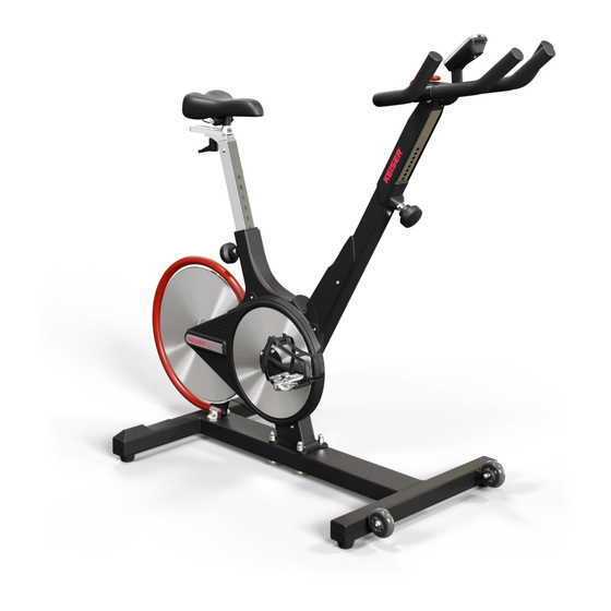
M3 Features 1 Saddle 2 Forward/Backward Seat Adjustment T-Handle 3 Up/Down Seat Adjustment T-Handle 4 Aluminum Flywheel 5 Sweat Guard 6 Water Bottle Holder 7 Up/Down Handlebar Adjustment T-Handle 8 Handlebars 9 Multi-Function Computer System 10 Resistance Shifter 11 Belt Cover 12 Shimano™ Combo Pedals 13 Cycle Base 14 Easy Transport Wheels... -
Page 4: M3 Computer System Features
M3 Computer System Features Line 1 RPM (Cadence) - The RPM display counts the cyclists revolutions per minute on one crank arm. RPM is known in the cycling world as Cadence and roughly is the speed at which the cyclist is pedalling. At above 140 RPM the word “STOP” will appear to indicate that the cyclist is pedalling faster than he or she needs to be. Line 2 Power - The power output is displayed in Watts (currently generating) and Kilocalories (total value for the ride). The computer toggles back and forth between Watts (displayed for eight seconds) and Kilocalories (displayed for two seconds). Line 3 Heart Rate - If there is no heart rate signal, a steady heart symbol and a zero will be displayed. If a participant is wearing a heart rate strap, and once the computer locks onto the signal, the heart symbol will blink and display the heart rate. Please note that the heart rate strap must be Polar™ compatible and coded. Line 4 Pedaling or Elapsed Time - The number... -
Page 5: Computer Installation
Computer Installation Tools needed for assembly: #1 Phillips screwdriver, #2 Phillips screwdriver... - Page 6 12. Calibrate The Computer, See Next Section...
-
Page 8: Mounting Computer
Mounting Computer Step 1: Obtain the #2 Phillips screwdriver and remove the computer mounting screw from the handlebar tube. Step 2: Coil the computer cable into the computer mount cavity. Step 3: Slide the computer up into the two locking ears. Insert and secure the screw you removed in Step 1 using the #2 Phillips screwdriver. Calibrating the Computer To calibrate the computer: The shifter lever must be in the down position. Holding a pedal, rotate the crank arm in any direction to switch the computer on. Once the computer is on, stop rotating the crank arm. Move the shifter lever from full bottom to full top a minimum of five times. When you see the computer display a set of number fives (55:55) in the time display, the computer is calibrated. -
Page 9: Computer Battery Replacement
Mounting Handlebar Assembly NOTE: If installing the M3 computer please do so before mounting the handle bars. When the computer installation is complete please return to this step. Step 1: Obtain the handlebar assembly, 6mm Allen wrench, and the socket head cap screws (M8x1.25 X 12 SS). Observe the location of the two mounting flanges on the handlebar post. Place the handlebar assembly on the post mounts, aligning the mounting holes. Step 2: Tilt the handlebar assembly slightly to place the socket head cap screws (M8x1.25 X 12 SS) into the mounting holes. Once each screw has been started, place the palm of one hand on the center of the handlebar pressing firmly and evenly onto the handlebar post. With the other hand tighten each screw with the Allen wrench until the head of each screw... -
Page 10: Assembling Bike To Base Frame
Assembling Bike to Base Frame Step 1: Carefully lower the bike onto the base frame over the base screws, with the front of the bike facing the transport wheels on the Base Frame. Step 2: Insert one washer on each of the four base frame studs. Step 3: Install the acorn nuts on the studs and hand tighten. Torque the acorn nuts with a 16mm or 5/8” crowfoot and torque wrench to 45 Nm (35 ft-lbs) using a 16mm, or 5/8 inch open-end wrench to hold in position. Assembling Pedal to Crank Arm Step 1: Unwrap the pedal set and Loctite 242, obtain the Torque wrench, 15mm crowfoot, 4” extension, and 15mm open-end wrench. Step 2: With a clean cloth, wipe the threaded area of the pedals. Apply Loctite 242 to the pedal threads. Install the pedals into the crank arms, use the 15mm open-end wrench to tighten. Finish with the torque wrench, 15mm crowfoot, and 4” extension. Torque pedals to 45 Nm (35 ft-lbs). NOTE: Left pedal is LH threads and right pedal is RH threads. WARNING! Failing to install the pedals with Loctite 242, or crossing the threads will damage them, and could result in serious injury to the user. -
Page 11: Assembling Flywheel, Hub, And Hub Cap
Assembling Flywheel, Hub, and Hub Cap Step 1: Before starting the assembly of the flywheel, hub, and hub cap, make sure that the shifter lever is in the downward position. NOTE: Not following this step may scratch the flywheel. Step 2: Remove the plastic wrapping from around the axle, hub, and hub cap. Remove the hub cap. Obtain the 5 socket head cap screws (M6x1 X 20 SS) and 5mm Allen wrench. -
Page 12: Resistance Mechanism Removal
Resistance Mechanism Removal... -
Page 14: Resistance Mechanism Installation
Resistance Mechanism Installation... -
Page 17: Steps For Belt Removal
Steps For Belt Removal... -
Page 18: Steps For Belt Installation
Steps for Belt Installation... -
Page 19: Crank Arm And Axle Removal And Installation
Crank Arm and Axle Removal and Installation... -
Page 22: Checking For Proper Operation
WARNING: Perform the operation below before riding to make sure the bike is fully operational. Failing to test a bike prior to normal use will void your warranty and could result in serious injury. CHECKING FOR PROPER OPERATION Pre-Ride Checklist Please inspect bike carefully and thoroughly before riding. All Parts Correctly Installed Acorn Nuts Torqued At 45 Nm (35 ft-lbs) Pedals Loctited and Torqued To 45 Nm (35 ft-lbs) All Screws and Nuts Properly Torqued and Tightened Handlebar and Seat Adjustments Operate Properly Bike Has Been Polished With Paste or Spray Wax and a Clean Cloth Computer Installed and Calibrated and In Working Order (See “Calibrating The Computer”) Test Ride... -
Page 23: Preventative Maintenance Chart
Preventative Maintenance Chart Every Class Member thoroughly inspect each cycle (1) Member wipe off sweat (2) Weekly for the 1st Month Check and re-torque crank arms and pedals (3) Weekly Thoroughly inspect each cycle (4) Clean with warm water and soft towel (5) Check computer for low battery indication (6) Monthly Check and re-torque crank arms, pedals, and main... -
Page 24: Keiser M3 Indoor Cycle Warranty Terms
Keiser shall in no event be liable for incidental or consequential losses, damages or expenses in connection with exercise products. Keiser’s liability hereunder is expressly limited to the replacement of parts not complying with this warranty or, at Keiser’s election, to the repayment of an amount equal to the purchase price of the parts in question. Keiser is not responsible for labor charges incurred in the replacement of defective parts. Keiser may, at its discretion, require the return of all defective parts. The customer is responsible for all transportation costs on warranted items to and from the point of manufacture. Replacement products are warranted for the balance of the original warranty period. All Keiser equipment sold by Keiser distributors, dealers, or salespeople must be registered for warranty purposes. The warranty registration form must be filed within 7 days of the sale or installation. Keiser equipment exported out of the US or Canada will be void of warranty unless purchased directly through a Keiser international distributor or dealer in the country of installation, or direct from Keiser’s international division. - Page 28 Questions? Please Contact the Keiser Service department 2470 S. Cherry Ave Fresno CA. 93706 Toll Free: 1.800.888.7009 Phone: 559.256.8000 Fax: 559.256.8100 www.keiser.com...
- Page 29 Lower the handlebar to the lowest position and re-secure the handle STEP 2. Tilt the M3 or M5 onto its transport wheels and lower it down, resting it on the handlebar. STEP 3. Remove the four existing glides with 3/16 hex. Discard old glides and hardware.
-
Page 30: Flywheel Guard Installation
Flywheel Guard Installation Equipment You Will Need 6mm Allen Wrench Two 10mm Wrenches Step 1: Make sure to have all parts and tools present prior to assembly. PARTS INVENTORY A) Bolt and Nut B) Brackets C) Tube... - Page 31 Step 2: Assemble the brackets (B) to the tube (C) With the bolt and nut (A) finger tight. Step 3: Make sure the flywheel is centered in the middle of the 2x4 tube of the base frame. Remove the two screws and washers from the base frame. These Screws will be used to mount the flywheel guard in step 4.
- Page 32 Step 4: Place the assembled flywheel guard over the holes and tighten brackets to the base frame with the screws and washers that were removed in step three (inset). Do not fully tighten the bolts. Step 5: Make sure the Tube is centered over the Flywheel. The Flywheel must be completely hidden behind the Tube as shown.
- Page 33 Center the tube with as much clearance as possible from the flywheel, then fully tighten all the bolts. If you experience any problems please contact our Service Department USA 1 (800) 888-7009 | International +1 (559) 256-8000 | service@keiser.com (800) 888-7009 keiser.com...
- Page 34 Keiser is committed to building the best products possible for our customers. It has come to our attention, that when seat posts on the M3 Indoor Cycle are not properly tightened, the seat post may become loose while riding. If you have experienced this at your facility, please contact our Service Department for further instructions.
Need help?
Do you have a question about the M3 and is the answer not in the manual?
Questions and answers