Keiser m3 User Manual
Hide thumbs
Also See for m3:
- User and service manual (34 pages) ,
- Quick start manual (2 pages) ,
- Assembly manual (2 pages)
Advertisement
Advertisement
Table of Contents

Related Manuals for Keiser m3


Summary of Contents for Keiser m3
- Page 1 USER MANUAL USER MANUAL...
-
Page 2: Table Of Contents
If parts are missing or damaged contact your local dealer, distributor or Keiser Corporation Service Department. After unpacking and verifying parts, you are ready to start your assembly. You need an area that is free of dirt, dust or other foreign material that could impair the assembly of your bike. - Page 3 - M3 Handlebar Assembly (550815). M3 + Handlebar Assembly procedure. It will include items A1-A5, and will require following the - Hub Cover Decals, will be shipped with, and are to be installed on M3/M3 + sold Item within the European Union only.
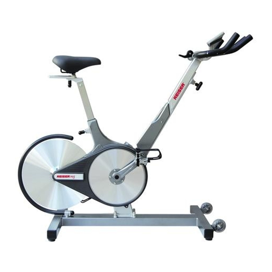
- Page 4 M3/M3 + INDOOR CYCLE M3 - 85 lbs (38.6 kg) / M3 + - 91 lbs (41.27kg) Total Bike Weight: M3 Footprint: Length 49 in (1245 mm) x Width 25.75 in (654 mm) Length 49.5” to 58.5” (1 257 mm to 1 485 mm) M3 + Footprint: x Width 25.75 in (654 mm)
-
Page 5: Bike Assembly
BIKE ASSEMBLY ASSEMBLING BIKE TO BASE FRAME Step 1: Carefully lower the bike onto the base frame over the base screws, with the front of the bike facing the transport wheels on the Base Frame. (Fig. 1) Step 2: Insert one washer on each of the four base frame studs. (Fig. 1) Step 3: Install the acorn nuts on the studs and hand tighten. - Page 6 NOTE: Use the foam envelope to handle the flywheel during assembly. Step 3: Carefully slide the flywheel between the two magnets (Fig 4. & Fig. 5) and onto the hub at the same time. Make sure that the flywheel is flush against the hub and align the screw holes.
- Page 7 Step 1 using the #2 Phillips screwdriver (Fig. 9). Computer mounting screw MOUNTING M3 HANDLEBAR ASSEMBLY FOR M3 + HANDLEBAR ASSEMBLY, PROCEED TO PG. 7 NOTE: If installing computer please do so before mounting the handlebars. Step 1: Obtain the handlebar assembly, 6mm Allen wrench, and the socket head cap screws (M8x1.25 X 12 SS).
- Page 8 MOUNTING M3 + HANDLEBAR ASSEMBLY Step 1: Remove screws from both sides of the Sweat Guard. Step 2: Slide on the Guard Cover and snap it over and align with the mounting holes of the Sweat Guard. Step 3: Replace both screws, but do not over tighten.
- Page 9 Step 7: Balance the Adjustable Handlebars on the Bottom Slide. Step 8: Locate the L-Handle Assembly, you will need to disassemble it in the following step. Step 9: Using a 5mm Allen wench remove the Screw and Washer, releasing the Handle Stud. Step 10: Clean Screw thread with alcohol, then apply Loctite 242 to leading edge of screw thread for handle bar adjust screw.
-
Page 10: Flywheel Guard Installation
Step 14: Fit the L-Handle to the Handle Stud. Position the L-Handle making sure that it is pointing to the front of the M3 + . Install the Screw and Washer. Make sure it is snug. Step 14: Loosen the L-Handle counter-clock wise. Slide the Handlebars back and forth, making sure they can move freely and be locked into all positions on the Bottom Slide. - Page 11 Step 4: Place the assembled flywheel guard over the holes and hold the tube guard as shown, to the left of the flywheel. Place the open end of the tube guard over the casting. Step 5: Swing the tube over the flywheel, aligning the tube centered with the flywheel. Step 6: Tighten the brackets to the base frame with the screws and washers that were removed in step three.
-
Page 12: Checking For Proper Operation
IMPORTANT SAFETY INFORMATION AND INSTRUCTIONS • The Keiser M3/M3 + is NOT designed with a freewheel, but a fixed gear system. When the flywheel is in motion, the pedals will also be in motion. Never remove your feet from the pedals while in motion as serious user injury may occur. -
Page 13: Bike Fitting
Serious injury or death can occur from over-training and should be taken very seriously. • The Keiser M3/M3 + is to be operated in a commercial fitness environment, all use should be supervised by a qualified fitness professional. - Page 14 HANDLEBAR HEIGHT ADJUSTMENT • The handlebars should be adjusted after performing the seat height adjustment. • Handlebars should be level or higher than the top of the saddle. • The elbows should be slightly bent and shoulders at approximately 90˚. •...
- Page 15 FORE AND AFT (FORWARD AND BACKWARD) SEAT POSITIONING • With the seat in the correct height position. Your arms should be a comfortable distance to the handlebars with the elbows slightly bent. Keep the hands on the handlebars while checking fore and aft positioning. WARNING: This adjustment shall not exceed the mark “STOP”...
- Page 16 An eddy current is an electrical current in a conducting material that results from induction by a moving or varying magnetic field. On the M3/M3 + , this is generated by the wheel passing through two opposing magnets. The flywheel (a conductor) passes through the magnetic field generated by the two powerful magnets.
- Page 17 assist both the instructor and participant by providing immediate feedback as well as tracking on-going improvement. By experiencing objective Cadence, Power Output, Gears and Heart Rate, the participant benefits from a better overall and more effective workout. The computer can also be used as a motivating tool to engage participants in their work- outs.
-
Page 18: Resetting Ride Averages/Elapsed Time/Distance
All M Series cardio equipment is calibrated with a tool at the factory and there is no need to calibrate, unless a component associated with the resistance mechanism or computer require service. For more information visit: www.keiser.com/service, or contact the Keiser service department at 1-800-888-7009 | 559-256-8000 | service@keiser.com. - Page 19 Check and re-torque crank arms and pedals (3) Check to ensure the four bolts attaching the Bottom Slide are tight. There should be no looseness or gap between the Bottom Slide and Slide mount. (M3 + ONLY) (9) Weekly Thoroughly inspect each Cycle (4)
-
Page 20: Warranty Terms
- Improper maintenance. - Improper assembly by the purchaser. - Failure to follow instructions as stated in any of the manuals provided with the Keiser M3/M3 + The warranty terms begin with the date of original delivery to be evidenced by appropriate shipping documents.
Need help?
Do you have a question about the m3 and is the answer not in the manual?
Questions and answers