
Subscribe to Our Youtube Channel
Related Manuals for PEERLESS SERIES TC


Summary of Contents for PEERLESS SERIES TC
- Page 1 Gas/Off Boilers Installation, Operation Maintenance Manual pr=-r=-I_Lr=-SS® CAST IRON BOILERS...
- Page 2 It)(ll'l'(llll{]. limit_,(l, lell Ill(" Ctl.g[ i!OII _('clioIl:q I.'q corn Ilr'l_'irl! I101 II_(ll('l (1!_(1 _;I¢'_llll t)oil_'t_. Fil_" (_ll(J I(!ll_!j('(lr (,xle_ded tValT(lltli_s pal_s (lilcJ I(lt)or (llx' llOII1 al,(lilable. PIt,(l.s_" ('(it_ s_l!l P_'_'l!_'s_; I$oil_'l% [})I _ olllplt'lt" II_(II_TUlI!I il!fi_llll(lliOII. Peerless Boilers • www.peerless-heater.com...
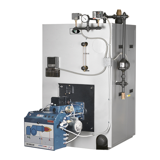
- Page 3 Oil, Gas or Combination Gas/Oil Boilers The Series TC cast iron boiler can be used in either hol water or steam systems. The oii, _.as or combination _.as/oil-fired boiler is available in 15 sizes and is ideal for lar_.e commerclal applications. The Series TC boiler is designed with forced draft firin_ to provide the highest possible efficiencies.
-
Page 4: Packaged Boilers
Series TC Standard Equipment • Insulated Enameled Steel Jacket • Cast Iron Flue Collector with Integral Damper • Bumer Mounting Plate with Insulation Block Series TO Features • Front and Rear Flame Observation Ports • Power Burners - Oil. Gas, Gas/Oil •... - Page 5 AIR REMOVAL MANUAL RESET /CONNECTIONS H]GH LIMIT OPERATING 1"BALL VALVE 5' TAPFEO_=CTIOI_ TEMP./PRESSURE (OPT.) GUAGE JAC_ CONTROL LOCATIONS (Water Boiler) MANUALRESET 64" NOTE OPERATING STEAM CONTROL PRESSURE GUAGE INTERMEDIATE SECTION • FRONT VIEW CONTROL LOCATIONS Note X- Flue cleanout opening. Allow 36" clear work (Steam Boiler) (Steam Boiler) space for using flue brush.
- Page 6 Add 2-3/4" to secllons 17 and 18 for flue oullet adapten *Based on 0.10 Ins. W.C. pressure al boiler outlet. If venl slzin_ results in a back pressure Qreater than 0.10 ins. W.C., consult Peerless Heater Compan% Tllese measLwemen?s are approximate.
- Page 7 Pump dischar_e size based on 15 PSI steam pressure and 20 PSI feed pump discharge pressure and feed valve In boller connection. Pipe size reductions are DOSslble, consult Peerless Heater Company. For multiple boiler Installatlons additional controls may be required to provide proper water level controls for all bo_lers.
- Page 8 200° Boiler Water - Number Drop - PSI Tapplngs The Peerless® Partner_ indirect-fired water heater providesa true advancement in hot water generation. By utilizing the Series TC 13.0 SM8-TC boiler as its heat source, the boiler fires only when necessary 11.0 SM12-TC 12.0...
-
Page 9: Table Of Contents
INSTALLATION USING THIS MANUAL A. STEAM BOILER PIPING ....A. MANUAL ORGANIZATION ....B. SPECIAL ATTENTION BOXES ... B. WATER BOILER PIPING ....C. TANKLESS HEATER INSTALLATION ..PREINSTALLATION " D. JACKET INSTALLATION ....A. GENERAL ......E. CONTROL TAPPING LOCATION ..B. - Page 10 7,_111 1_vl F±IL_ t IY'..! II [e] *'{€'7-'1 b ,'_l V.J'-_I II[*] L _ The Series TC Installation, Operation & Maintenance Indicates a condition or hazard which will cause Manual is divided into five basic sections: severe personal injury, death or major property damage.
-
Page 11: Boilers
Sides: 6" '-'1 [_ :lOl:l;_r.*1 2. Rear of Jacket: 6" Series TC boilers are supplied completely knocked down 3. Front of Boiler: 24" for field assembly, completely assembled as packaged boilers or as assembled blocks of sections. All items 4. Top of Jacket: 6"... - Page 12 d) Breeching used w ithforced d raft b oilers must be I::m [_o]Lv_l:_lk'li[o]b,_l.'livdqLlilllr-'ll[o]L_l F-'II: sealed andofheavy g auge s teel construction. Breeching must comply w ithallapplicable codes Provide adequate air for combustion and ventilation. ofconstruction. Unless boiler room construction and natural air infiltration supply all necessary combustion air, provide an outside air opening or duct.
- Page 13 "I_.'_-"I-'] 5F'ul :]led HOLES FOR MOUNTING LOWER Careful inspection should be made of all assemblies to detect possible damage during shipment. Factory JACKET CHANNELS assembled blocks of sections and package boilers are hydrostatically tested at the factory to insure pressure tightness.
- Page 14 Step 11 Upper Left ..30 ft Ibs. Install two smaller port connectors in the lower recessed ports. Step 12 UpperRight . . .125 ft. Ibs. Note: If port connectors will not stay in place: Use Step 13 Lower Left .
-
Page 15: Rear Observation Port
Table Arrangement of Sections Steam Boilers 4Section-F 5Section-F-H-T-H F - Front Section 6Section-F H-T-H-B T - Intermediate Section with 5" Tapping 7Section-F-T-H-P-T H - Optional Intermediate Heater Section 8Section-F-T H-T-H-B P - Plain Intermediate Section 9Section-F T-H-P-H B - Back Section 10 Section-F-H-T H-P-T-H-B 11 Section-F... - Page 16 l :N 3 KIJ :! :{o):| h'_F.'_I I t;1 nn |;_1 i [o] _ Screw the 5/16" studs into the screw seats around the Most large burners require support from the floor. flue box outlet on the back section. Place I/8" x 3/4" x See Burner Manufacturer's Manual for such 86"...
-
Page 17: Installation
Table 3 b._lll:!'_'W_ll:{o]lll_l:t I'_l'.lh_[_ Steam Boiler Feedwater Recommendations Steam piping schedule is shown in Table 2. Pitch the I=B=R Minimum Condensate piping to allow condensate to t_ow in the same Gross Evap Feedwater Receiver direction as the steam. Refer to Figure 6 for an Boiler Output... -
Page 18: Water Boiler Piping
TC-W-6-9 7658 Tee 4" x 4" x 5" TC-W-10 7659 Tee 4" 2. Series TC Return Yoke Assembly, Grooved Pipe (4 to 18 sections} a) Cover edges and outer surface of the gasket with 7663 Lube 4.5 oz. a thin layer of petroleum-free silicone lubricant or equivalent. -
Page 19: Jacket Installation
1/4" - 20 round The boiler must be completely assembled on base angles head screws, washers and nuts. supplied by Peerless Heater Company. These are drilled and tapped to accommodate lower jacket channels. Upper Channels,... - Page 20 SUPPORT BRACKETS RIGHT REAR POST LEFT REAR POST \UPPER CHANNELS, BASE ANGLES (NOT INCLUDED WITH JACKET) Figure 12: Jacket Assembly...
- Page 21 FI_-"] _ ! mE_i['L r Table 5: Jacket Schedule Jacket Channel Carton Upper Channels Lower Channels 1318 2 J2 Channel Carton Hardware {17) 1/4" - 20 x 3/4" Slot, RD, Head Machine, Screws, Zinc Plated (17} 1/4" ID Washe_, Zinc Plated (17) 1/4"...
- Page 22 :Ill .D] L_ i II;To)nil If_,1 :J:JI_[€"I I(o0D.Y±_l | [o] L_ Figure 13 shows the location of tappings for controls and piping for both water and steam boiler. Tappi.g Tapping Steam Water Size Boiler Boi]eT 3/4" Probe LWCO I" Water Column Air Removal 3/4"...
-
Page 23: Piping
1" PIPING L.W.C.O. __A?E OPT') L.W.C.O. Series TC Series boilers are available with a variety of (OPT.) water level control devices. Figure 14A shows a typical water column piping arrangement. For all installations, the 1" x 7-I/2" hydronic nipple is installed in the lower water column tapping. - Page 24 t-'_if:1;t/h_[Cli|:l= I:{e]lq:l" 2. If the system requires antifreeze, use only antifreeze designed for hydronic systems. These contain inhibitors to prevent corrosion Check the piping. of the boiler and system components. Do not Water/Steam Piping use ethylene glycol or automotive antifreezes. The Boiler must have been hydrostatically •...
- Page 25 5. Check boiler controls. Close all valves to the system. Provide a means of continuous fresh water to the boiler for the cleaning a) Limit and Operating Controls process. 1. Lower the setting of each control until the burner shuts down. Open the skim valve.
- Page 26 4. Be certain that the boiler and system are refilled before returning to service Follow the instructions in this manual and the burner instructions to operate. Do not store or allow combustible or flammable materials near the boiler. Substantial fire or explosion hazard could result, causing risk of personal injury, Before servicing the boiler: death or property damage.
- Page 27 WATER BOILERS: Avoid thermal shock of water boilers. Establish water circulation through the boiler before starting burner. Where hot standby is required, special piping and operation procedures are required. Consult your Peerless Heater Company representative.
- Page 28 _'J! _.._ __. • _ _.._ D" CJ"_ ,.-._t.,Q 34..-..-.-_ ,,D_ _.t_...
- Page 29 Table 7: Series TC Repair Parts Burner Insulating Block Hardware 7720 ! Front Section 76000 Observation Glass Only 7648 Intermediate Section 76002 Observation Glass Gasket 7650 lnlermediate Section w,Heater Connection 76004 Observation Glass Gaskel 7649 Intermediate Section w, Supply Connection...
-
Page 30: Maintenance
Qualified Service Agency. member HI Division ASME of gama PEERLESS" CAST IRON BOILERS PEERLESS HEATER COMPANY 231 NORTH WALNUT STREET - BOYERTOWN, PA 19512-1021 . PHONE 610-367-2153 www.peerless-heate_com PREFERRED HEATING CHOICE @2002 Peerless Heater...
Need help?
Do you have a question about the SERIES TC and is the answer not in the manual?
Questions and answers