Table of Contents
Advertisement
Quick Links
Advertisement
Table of Contents

Related Manuals for Windster RA35U30SS


Summary of Contents for Windster RA35U30SS
-
Page 2: Table Of Contents
TABLE OF CONTENTS Table of Contents Safety Information .............. 2 Content Checklist ..............4 Measurements ................5 Preparation ................6 7 Installation ................8 Installation Diagram ..............10 Operation & Features ............. 11 Cleaning & Maintenance ............13 Troubleshooting ..............14 Part List / Replacement .......... -
Page 3: Safety Information
SAFETY INFORMATION SAFETY INFORMATION TO REDUCE THE RISK OF A FIRE, ELECTRICAL SHOCK, AND/OR INJURY OBSERVE THE FOLLOWING: Unit is intended for indoor residential use only. If you should have questions, contact the manufacturer at the address or telephone number listed in the warranty. -
Page 4: Safety Information 2
SAFETY INFORMATION TO REDUCE THE RISK OF FIRE, OR ELECTRIC SHOCK, DO NOT USE THIS FAN WITH ANY SOLID-STATE SPEED CONTROL DEVICE. Regardless of heat level, never leave any surface materials unattended while operating an open flame. Always turn hood ON when cooking at high heat or when flambéing food (i.e. Crepes Suzette, Cherries Jubilee, Peppercorn Beef Flambé). -
Page 6: Measurements
MEASUREMENTS... -
Page 7: Before You Start
PREPARATION PREPARATION BEFORE YOU START **DO NOT INSTALL IF DAMAGED** **RETURN OR EXCHANGE WILL BE DENIED IF INSTALLED** Be sure you have all the content of your purchase and required tools for this installation. Installation may take at least 2 to 3 hours from start to finish. Plan to use as few elbows or turns as possible for more efficient air flow. -
Page 8: Preparation
PREPARATION For cabinet with recessed-bottom, use (2) 3 wood strips on both sides to balance the recession. Use (4) 1- screws to secure the wood strips to cabinet. (Fig. 1d) HOOD Inspect for any sign of defect or damage. (ie. scratches, dents, loose seams, etc.) Power up the unit to make sure it is working properly. -
Page 9: Installation
INSTALLATION INSTALLATION 1. UNDER CABINET INSTALLATION Make sure all preparation steps are completed. Feed the wires coming out of the hood through the bottom of the cabinet. Lift the unit up flush against the wall and the bottom of the cabinet. Using the screws and washers provided, insert into each of the keyhole openings and tightly secure the unit against the bottom of the cabinet. -
Page 10: Installation 8
INSTALLATION 3. COLD WEATHER INSTALLATION (OPTIONAL) Check with your local building codes to see if a CFM reducer is an acceptable alternative to make-up air. Remove the RA35CFMR (CFM Reducer) and inspect for any sign of defect or damage. (ie. Cracks, broken flips) For UNDER CABINET installation: COMPLETE Step A D of Section 1 UNDER CABINET INSTALLATION THEN GO TO STEP E BELOW. -
Page 11: Installation Diagram
INSTALLATION DIAGRAM INSTALLATION DIAGRAM Fig. 2a Fig. 2b Fig. 2c Fig. 2d... -
Page 12: Operation & Features
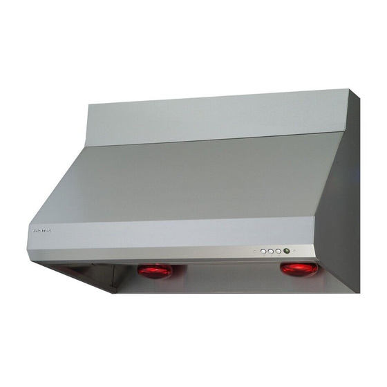
OPERATION & FEATURES OPERATION & FEATURES EASY ACCESS CONTROL SWITCH (from left to right) Button 1 ON / DELAY SHUTOFF / OFF Button 2 Light control Button 3 Speed control Blue color speed indicator HEAT LAMP LIGHTING (2) 250w heat lamp (NOT INCLUDED) BAFFLE FILTERS (2) 14-3/4 11 baffle... - Page 13 OPERATION & FEATURES PUTTING IN THE OIL TRAY AND BAFFLE FILTERS Insert the oil tray into the unit at an angle and slide it down at the slot located next to the heat lamp sockets. (Fig. 3a) Slide the baffle filter into the hood. Push the baffle filter upward.
-
Page 14: Cleaning & Maintenance
CLEANING & MAINTENANCE CLEANING& MAINTENANCE WARNING!!! To prevent the possibility of a fire and explosion, do not use flammable liquids or solvents to clean the unit or any of its parts. Check to make sure all power sources are disconnected before servicing or taking unit apart for cleaning. -
Page 15: Troubleshooting
TROUBLESHOOTING TROUBLESHOOTING WARNING!!! Check to make sure all power sources are disconnected before starting any troubleshooting. Safety gloves and glasses should be worn when working on the unit. Serious injury or death may occur if safety precautions are not followed. RA35 Series Light Issue (All not 1. -
Page 16: Part List / Replacement
PART LIST / REPLACEMENT PART LIST / REPLACEMENT... - Page 17 PART LIST / REPLACEMENT Description Description Duct cover (optional) Support panel Hood bracket (optional) Transformer Hood body assembly Capacitor Oil tray bar Squirrel cage motor x 2 Heat lamp light socket (2) baffle LED lights Control switch Control board...
-
Page 18: Limited Warranty
For a period of one (1) year from the date of purchase, if the product is determined to be defective, Windster will attempt to repair the product, at its option, at no charge. After the warranty period, customer must pay for all labor charges. During the "labor"... -
Page 19: Warranty / Contact
Aluminum Filters, Baffle Filters, Charcoal Filters, and Oil Cup Filters Light Bulbs CONTACT US Windster Hoods, Inc. 5101 Commerce Dr. Baldwin Park, CA 91706 TEL: (626) 962 8600 FAX: (626) 962 8669 Toll Free: (877) 350 5215 E-mail: Support@windsterhood.com © Windster Hoods, Inc. Information subject to change without notice...
Need help?
Do you have a question about the RA35U30SS and is the answer not in the manual?
Questions and answers