
Related Manuals for Lab.gruppen Lake LM 26

Summary of Contents for Lab.gruppen Lake LM 26
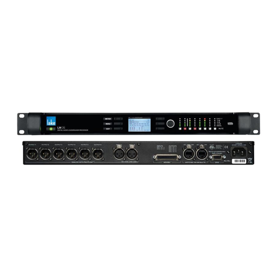
- Page 1 Operation Manual Lake LM 26 ® Digital Audio Loudspeaker Processor Rev 1.1.8 Item: OM-LM26...
-
Page 2: Important Safety Instructions
Important Safety Instructions 1. Important Safety Instructions Before using the device, be sure to carefully read the Safety Instructions. Keep this document with the device at all times. Important Safety Instructions To prevent electric shock do not remove top or bottom covers. No user serviceable parts inside, refer servicing to qualified Read these instructions. -
Page 3: Warning
Important Safety Instructions WARNING To reduce risk of fire or electric shock, do not expose this apparatus to rain or moisture. Pour réduire les risques de blessure ou le choc électrique, n’exposez pas l’appareil à la pluie ou à l’humidité. Do not expose this system/apparatus to dripping or splashing and ensure that no objects filled with liquids, such as vases, are placed on the apparatus. -
Page 4: User Responsibility
Important Safety Instructions ▸ Check if the affected unit complies with the EMC limits for immunity, (CE-labeled). If not, address the problem with the manufacturer or supplier. All electrical products sold in the EC must be approved for immunity against electromagnetic fields, high voltage flashes, and radio interference. ▸... -
Page 5: Table Of Contents
Table of Contents Important Safety Instructions ........................i Important Safety Instructions ....................... i Standards .............................. i Explanation of Graphical Symbols ......................i WARNING ............................ii CAUTION ............................. ii FCC Compliance Notice (Radio Interference) ..................ii User Responsibility ..........................iii Welcome ..............................1 Introduction ............................1 Main Features ............................1 Additional Documentation ........................2 Installation ..............................3... - Page 6 Back Panel Interface ..........................38 Analog Inputs and Outputs ........................38 AES3 Digital I/O ..........................40 RJ45 etherCON Network Connections ....................42 ® GPIO Connection ..........................43 Universal Power Supply Connection ....................44 Appendix ..............................45 Faults and Warnings Overview ......................45 Maintenance ............................46 Factory Default Settings........................46 Glossary of Terms, Acronyms and Abbreviations ................47 Application Guide ..........................50 Gain Structure ............................50 Gain / Level Optimization ........................
-
Page 7: Welcome
2. Welcome Introduction Thank you for choosing the Lake LM 26. We are confident that you will be pleased with the performance, unique features, configuration flexibility, reliability, and long-term durability offered by this product. For fast installation and use of this product, your welcome package includes a printed copy of the LM 26 Quick Start and Field Reference Guide which contains the information required to safely install the product and place it in service. -
Page 8: Additional Documentation
Audio Network ™ The Lake LM 26 includes Dante digital audio networking as standard. Utilizing the latest advances in Eth- ernet technology, Dante offers simplified system configuration and extremely low latency while delivering very high quality uncompressed digital audio across the Lake network. The Zen automatic configuration ™... -
Page 9: Installation
Cooling The Lake LM 26 uses a forced-air cooling system, with airflow from right to left. The dust filter on the air intake (right-side) should be regularly cleaned, especially after exposure to dusty environments, to ensure the maximum possible airflow through the unit. -
Page 10: Operating Voltage
Installation ▸ At 55 C (131 F ) a temperature warning is indicated on the front panel as ‘TEMP WARNING’ and in the Controller Event Log as ‘Temp warning: DSP area’. ▸ At 70 C (158 F ) the LM 26 has exceeded the maximum normal operating temperature. This fault is indicated on the front panel as ‘OVERTEMP’... -
Page 11: Product Overview
Product Overview 4. Product Overview This chapter provides and overview of key features and functionality. For further information please see chapters to 9 of this Operation Manual. Front Panel Overview Figure 4-1: LM 26 Front Panel Overview The front panel controls are clustered around a daylight readable LCD , allowing adjustment and monitor- ing of the majority parameters and meters. - Page 12 Product Overview Display The display illuminates when the device is on. The LCD, function buttons, and the rotary encoder provide real-time control and monitoring of most parameters. The LEDs embedded in the function buttons indicate available menu options, provide confirmation of Controller communication, and indicate various faults and warnings.
-
Page 13: Back Panel Overview
Product Overview Dynamic Function Buttons with LEDs (Right of LCD) The function of these buttons change according to the currently selected view or menu. The right bi-color LED in the top button illuminates red or yellow to indicate faults or warnings. If this button is pressed while in Home View, and with the Lake Controller on the Home page or the Modules Menu, then Module B of the selected frame will be highlighted in the Controller. - Page 14 Product Overview Analog Outputs Six analog outputs are provided via standard XLR3M connections. The outputs are electronically balanced and feature Lake Iso-Float circuitry. The output impedance is 50 ohms, providing a maximum output level of +21 dBu. Please refer to section 7.1 for further information. Analog Inputs Two analog inputs are provided via standard XLR3F latching connectors.
- Page 15 Product Overview Secondary Connector The secondary network connector can be used to daisy-chain multiple PLM Series, LM 26 and legacy Lake devices. Alternatively, a dual-network topology can be created by connecting all secondary network connec- tors to a separate Ethernet switch, ensuring full redundancy in the event of a network component failure. Additional processor configuration is required for a dual redundant network setup.
-
Page 16: Signal Flow And Lake Processing
Signal Flow and Lake Processing 5. Signal Flow and Lake Processing Signal Flow Figure 5-1 depicts the audio signal flow inside an LM 26. It is worth noting that this sophisticated device provides five points in the signal chain where the signal level can be adjusted, muted or disconnected. Important information regarding correct setting of the gain structure can be found in section 9.1. -
Page 17: Lake Processing And Control
Signal Flow and Lake Processing Input routers 1-4 provide all five stages of functionality via the front panel interface or the Lake Controller. The pass-thru input routers 5&6 allow stage 1 input selection only (MUTE is unavailable), along with stage 5 output ON/OFF routing connections. -
Page 18: Loudspeaker Crossover Configuration Overview
Signal Flow and Lake Processing The key benefit of this feature is the ability to connect and control crossovers, levels and EQ across multiple hardware devices simultaneously from the Lake Controller. For example, one device may be driving sub and low-frequency speakers, while another device controls mid-range and hi-frequency drivers. - Page 19 Signal Flow and Lake Processing 5.5.2 Frame and System Presets This device allows the complete processor configuration to be stored as a Frame Preset on the hardware unit itself. Presets can be recalled via the front panel (please refer section 6.10.6) to or via the Lake Controller software (please refer to the Lake Controller Operation Manual.
-
Page 20: Front Panel Interface
Front Panel Interface 6. Front Panel Interface An overview of the front panel interface is provided in section 4.1. This chapter describes each cluster of controls as shown in Figure 6-1. Figure 6-1: Front Panel Interface Overview The majority of LM 26 functions can be controlled and monitored via LCD display screen , function buttons , rotary encoder... -
Page 21: Front Panel Key Lock
Front Panel Interface 1. Ensure Meter Mode is selected 2. Press the button adjacent to the Module description on the LCD If the Frame is online, but the Module is not in the work area, the selected Module will be centred on the Module scroll bar (assuming the Modules Menu is selected in the Lake Controller). -
Page 22: Menu Button
Front Panel Interface Menu Button Menu Mode is selected by pressing the MENU button . The screen displays the top level menu with various submenu options. Press the button adjacent to the required submenu to select it. Pressing the MENU button while in Menu Mode will display the previous menu level. Menu Mode is used for processor configuration, or for editing a parameter. -
Page 23: Rotary Encoder
Front Panel Interface 6.7.2 Faults and Warnings LED This bi-color LED turns red to indicate a fault or mute state and turns yellow to indicate a warning. Additional clarification of the fault or warning is displayed in the LCD. Table 6-1 describes the fault and mute states displayed of the front panel, which are signified by a red LED. - Page 24 Front Panel Interface Turn the encoder clockwise to increase the selected parameter, or counter-clockwise to decrease the value. Parameters with only two states (e.g. ON, OFF) are toggled by turning clockwise or counter-clockwise. Some parameters enable simultaneous adjustment of a combination of input and output channels. To select which channels are adjusted: 1.
-
Page 25: Module I/O Mute Buttons And Led Meters
Front Panel Interface Module I/O Mute Buttons and LED Meters The LM 26 provides mute functions at several points in the audio signal path. Please refer to section 5.1 for mute locations and descriptions. Three types of mute are available from the front panel: 1. -
Page 26: Meter Mode
Front Panel Interface 6.8.2 Clip Indication The dedicated 5-segment metering LEDs (Figure 6-4 ) display Module input and output clip or pre-clip conditions. Additionally, the faults and warnings LED described in section provides clip warnings for LM 26 input mutes, or GPIO protective mutes, along with confirmation text on the LCD screen. Clipping is monitored at the following positions in the signal chain: ▸... -
Page 27: Menu Mode
Front Panel Interface Figure 6-6: Meter Mode > I/O Status View This section displays the screen title (left) and frame fault or warning description (right) This section displays confirmation of the following settings: ▸ Dante Clock Master (no icon = Dante Slave or Dante Disabled) ▸... - Page 28 Front Panel Interface After pressing the MENU button, various submenu options are displayed as shown in Figure 6-1. Figure 6-7: Menu Mode > Main Menu Press the illuminated button adjacent to the required option to display an associated submenu. When parameter level is reached, individual parameters may be selected for adjustment by pressing the adjacent button.
-
Page 29: Module Submenu
Front Panel Interface 6.10.1.2 Menu Structure Overview From the Main Menu, the following submenus are available, as shown in Figure 6-7 and described in the following sections. ▸ MODULE (See section 6.10.2) ▸ Mixer Gain ▸ Gain ▸ Delay ▸ Polarity ▸... - Page 30 Front Panel Interface Figure 6-8: Module Submenu 6.10.2.1 Mixer Gain MENU > MODULE > MIXER GAIN Figure 6-9: Module Input Mixer Gain Edit Screen The top left button labeled PAGE toggles between the input mixer gain settings for each Module in the Frame.
- Page 31 Front Panel Interface Figure 6-10: Single Module Gain Edit Screen Pressing the top left PAGE button scrolls between the following three views for modules with four output channels or less: 1. Module A Input and Output Gain Settings (with Group totals) 2.
- Page 32 Front Panel Interface The audio signal may be delayed (typically for reasons of driver or delay subsystem alignment) at either the Module inputs or on individual outputs. Delay added at the inputs affects all outputs equally, and will be generally be introduced to time-align arrays of loudspeakers at different locations. Delaying individual outputs may be desirable to time-align drivers in the same cabinet or array.
- Page 33 Front Panel Interface The Corner parameter is adjustable in 0.1 dB increments, subject to defined level limits. This figure repre- sents the level below the limiter threshold at which compression commences; the larger this negative value, the softer the knee. A setting of 0 dB implies a hard-knee characteristic. LimiterMax provides peak and RMS limiting features, referred to as MaxPeak and MaxRMS respectively.
- Page 34 Front Panel Interface Figure 5-1 on page 10 shows that there are six Input Routers available on the LM 26. The signal from the first four Input Routers can be routed to the Input Mixer for Module A & B, or directly to any output. The first four input routers act as a switch, permitting one channel per router to be passed into the input mixers or directly to any output.
- Page 35 Front Panel Interface Analog Input Sensitivity and Digital Gain Offset While viewing the Input Router screen as shown in Figure 6-13, press PAGE to reveal existing input sensitiv- ity for analog inputs, or digital gain offset for digital inputs. This is equivalent to the DISPLAY DETAILS option in the Lake Controller.
- Page 36 Front Panel Interface 6.10.3.3 Iso-Float MENU > I/O CONFIG > ISO-FLOAT Figure 6-15: Iso-Float Menu To change the Iso-Float setting, press the Inputs or Outputs button, then adjust the value using the rotary encoder. The current settings are also displayed on the front panel I/O STATUS screen. The analog inputs utilize Iso-Float transformerless electronic balancing circuitry.
-
Page 37: Frame Submenu
Front Panel Interface Press this button to move the cursor upwards Press this button to move the cursor downwards This section of the screen displays the selected audio source This section of the screen displays the selected output destination type This section of the screen displays the channels for the selected audio source This section of the screen displays the output routing configuration Press this button to scroll through the available output destination types... - Page 38 Front Panel Interface The Frame Menu provides information and options relating to the LM 26 as a physical unit. It is referred to as a Frame for consistency with Lake Controller terminology. 6.10.4.1 Frame Info MENU > FRAME > FRAME INFO Frame Info provides information about the device settings and configuration.
- Page 39 Front Panel Interface 6.10.4.2 Frame Reset MENU > FRAME > RESET Use this option to display a further menu with options to reset all parameters back to their original factory default values. See section 8.3 for a full list of these values. Two types of reset are provided, Factory Reset and Soft Reset.
- Page 40 Front Panel Interface GPI Configuration To adjust GPI 1 or GPI 2, press the associated button to display a screen similar to that shown in Figure 6-19. Figure 6-19: GPI Configuration Table 6-3 lists the options available for General Purpose Input (GPI). These options can be set independently for a transition from closed >...
- Page 41 Front Panel Interface GPO Configuration To adjust GPO 1 or GPO 2, press the associated button to display a screen similar to that shown in Figure 6-20 Figure 6-20: GPO Configuration Table 6-4 lists the options available for General Purpose Output (GPO). Acting on State when Closed 1.
- Page 42 Front Panel Interface GPIO # Default Option GPI 1 No Action GPI 2 No Action GPO 1 Standby State GPO 2 Fault Table 6-5: Default GPIO Configuration 6.10.5 Front Panel Display Controls MENU > FRAME > FRONT Figure 6-21: Front Panel Display Controls Menu Contrast To adjust the front panel LCD contrast, select this option then use the rotary encoder to change the value.
- Page 43 Front Panel Interface To recall an existing Frame Preset, use the rotary encoder to select the required Preset then press the RECALL button to overwrite the current configuration. Frame Presets must initially be created in the Lake Controller, and stored as a Preset using the Lake Controller or Lake Preset Manager.
-
Page 44: Back Panel Interface
Back Panel Interface 7. Back Panel Interface An overview of the back panel interface is provided in section 4.2. This chapter describes each cluster of connections as shown in Figure 7-1. Figure 7-1: Back Panel Interface Analog Inputs and Outputs 7.1.1 Analog Output XLR Connections Six electronically-balanced analog outputs are provided via standard XLR3M connections. -
Page 45: Unbalanced Operation
Back Panel Interface 7.1.3 Analog XLR Wiring and Pin Out All XLR connections are wired to IEC268 as shown in Figure 7-4. Figure 7-4: IEC268 XLR Wiring and Pin Out Pin 1: Ground / Shield Pin 2: Hot (+) Pin 3: Cold (-) 7.1.4 Unbalanced Operation... -
Page 46: Aes3 Digital I/O
Back Panel Interface SCRN SCRN Unbalanced Output Balanced Input (Typically phono) (XLR) Figure 7-6: Unbalanced Analog Wiring and Pin Out 7.1.5 Iso-Float Electronic Balancing The analog input and output electronic balancing circuits use the Lake Iso-Float system. The Iso-Float technology combines the benefits of transformer-coupled isolation with the advantages of clean, direct-coupled inputs and outputs. - Page 47 Back Panel Interface AES3 Inputs AES3 Outputs AES1: Ch. 1 & 2 AES1: Ch. 1 & 2 AES2: Ch. 3 & 4 AES2: Ch. 3 & 4 AES3: Ch. 5 & 6 AES4: Ch. 7 & 8 Table 7-1: DB25 Input and Outputs Figure 7-8 below provides a wiring reference for the DB25 connector.
-
Page 48: Rj45 Ethercon ® Network Connections
Back Panel Interface RJ45 etherCON Network Connections ® Two RJ45 etherCON style network connections are provided as shown in Figure 7-9. PRIM LINK SEC LINK SWITCHED 100/1000 Base-T Figure 7-9: etherCON Network Connectors The network connections auto-sense whether standard or crossover Cat-5e cables are in use. Pre-made cables with moulded RJ45 plugs are recommended. -
Page 49: Gpio Connection
Back Panel Interface 7.3.1 Primary Network Connection The Primary Network connection is used for Lake Controller connectivity and Dante digital audio. Please refer to section 4.2 for additional information. 7.3.2 Secondary Network Connection The Secondary Network connection may be used for a redundant Dante digital audio network. Please refer to section 4.2 for additional information. -
Page 50: Universal Power Supply Connection
Back Panel Interface Universal Power Supply Connection 7.5.1 IEC Power Connector A universal power supply capable of accepting 70-265 V ~ 50-60 Hz : 30 W is built into the LM 26. The IEC power cable provided includes a locking feature via a pin on the bottom of the connector; the connector can accept standard or locking IEC power cables. -
Page 51: Appendix
Appendix 8. Appendix Faults and Warnings Overview Fault or warning conditions are indicated by the LED shown in Figure 6-3 on page 16. As the LED indicates several types of faults or warnings, a brief textual description of the fault or warning is provided on the LCD display. -
Page 52: Maintenance
Appendix Maintenance During normal operation this devices provides trouble-free service. If the LCD or front panel display requires cleaning, use a soft cloth only; do not use solvent cleaners. The dust filter on the right-hand side air intake should occasionally be removed and cleaned to ensure maximum airflow through the device. Disconnect the unit from mains power prior to removing dust the filter, and ensure the dust filter is replace prior to turning the unit back on. -
Page 53: Glossary Of Terms, Acronyms And Abbreviations
Relevant only to PLM Series devices. Short for Current Peak Limiter, a Lab.gruppen protection technique which ensures that the amplifier’s output transistors can never attempt to deliver more than their rated current. - Page 54 A device on an Ethernet network which is fully operational and communicating with the rest of the network is said to be online. Relevant only to PLM Series devices. Short for Power Average Limiter, PAL is proprietary Lab.gruppen circuit which provides additional amplifier protection.
- Page 55 Secondary Ethernet Port connection of a separate second network for full redundancy. Relevant only to PLM Series devices. A Lab.gruppen proprietary protective circuit designed to mute a channel when a short circuit is Short Circuit Protection detected at its output terminals to prevent damage to the device.
-
Page 56: Application Guide
Application Guide 9. Application Guide This chapter describes the practical application and use of the LM 26. Gain Structure The LM 26 architecture provides gain adjustments at various points in the signal path and therefore, various places for muting and level adjustment. Each mute or gain adjustment point serves a different purpose. The signal flow diagram in chapter 5 provides a useful reference for the signal path. -
Page 57: Gain / Level Optimization
Application Guide 1. Factory Gain is set by the system designer and can be hidden within the Module file. The Factory Gain parameter is only accessible when the Module is unlocked and the Lake Controller is in Designer Mode. Adjust via MODULES > LEVELS > METER OPTIONS > ADJUST FACTORY. 2. -
Page 58: System Latency And Delay Compensation
Application Guide 9.3.1 AES3 Digital Audio The original AES/EBU digital audio interface standard was developed by the Audio Engineering Society in conjunction with the European Broadcast Union. Originally published in 1985, it was revised in 1992 and 2003, and in its current iteration it is properly designated the AES3 standard. AES3 is a serial transmission format for linearly represented (uncompressed) digital audio data. -
Page 59: Digital Clock Configuration
Application Guide 9.3.3.2 Passive splitters In some limited applications, a single AES3 input may be split into two signals using a simple passive splitter. Splitters provide a convenient and low cost solution when only one additional signal is required, and in situations where cable lengths are short. - Page 60 Application Guide In Figure 9-1, each circled C represents a choice point. A choice point is a user‐interface control that can be configured using the Lake Controller software. Please refer to the Lake Controller Operation Manual for further information. Figure 9-1 indicates internally generated clocks with base-rate multiples of 44.1 kHz or 48 kHz.
- Page 61 Application Guide When using automatic detection, the AES3 digital input is monitored and will switch the clock source back and forth depending on the availability of an AES3 signal. Please refer to the Lake Controller Operation Manual for additional information. 9.4.3 Dante Clock Configuration Dante uses its own digital clocking technology across the Ethernet network to ensure that all Dante devices...
-
Page 62: Technical Specifications
Technical Specifications 10. Technical Specifications e fi c s LM 26 2-in/6-out Digital Audio Loudspeaker Processor 2 Contour Modules Raised Cosine Mesa and Ideal graphic input equalizer Linear phase and classic crossovers and output EQ LimiterMax peak and RMS limiter Delay, mute, phase, gain Audio Performance Internal sample rate... -
Page 63: Warranty And Support
Warranty and Support 11. Warranty and Support 11.1 General This product is manufactured by Lake, and it is warranted to be free from any defects caused by compo- nents or factory workmanship, under normal use and service, for a period of three (3) years from date of purchase from an authorized Lake dealer. -
Page 64: Trademarks
11.4 Trademarks Lake is a national and/or international registered trademark of Lab.gruppen AB. PLM, Powered Loudspeaker Management and LM 26, are trademarks of Lab.gruppen AB. Dolby is a registered trademark of Dolby Laboratories. Raised Cosine Equalization, LimiterMax and Iso-Float are trademarks of Dolby Laboratories. - Page 65 I N T E R N A T I O N A L C O N T A C T ► I N F O @ L A K E P R O C E S S I N G . C O M U S & C A N A D A C O N T A C T ► I N F O @ T C G - A M E R I C A S . C O M w w w .
Need help?
Do you have a question about the Lake LM 26 and is the answer not in the manual?
Questions and answers