
Related Manuals for Kramer VP-725DSA


Summary of Contents for Kramer VP-725DSA
-
Page 1: User Manual
Kramer Electronics, Ltd. USER MANUAL Model: VP-725DSA Presentation Switcher / Scaler... -
Page 2: Table Of Contents
Getting Started Quick Start Overview Your VP-725DSA Presentation Switcher / Scaler Installing on a Rack Connecting the VP-725DSA Presentation Switcher / Scaler Connecting the MASTER OUT Terminal Block Connector 6.1.1 Using the MASTER OUT in the Master Audio Mode 6.1.2... - Page 3 VP-725DSA Communication Protocol VP-725DSA Text Overlay Protocol Figures Figure 1: VP-725DSA Presentation Switcher / Scaler Front Panel Figure 2: VP-725DSA Presentation Switcher / Scaler Rear Panel Figure 3: Connecting the VP-725DSA Presentation Switcher / Scaler Figure 4: Connecting the MASTER OUT (in Master Audio Mode)
- Page 4 Contents Figure 14: OSD SWAP Status Figure 15: Locking / Unlocking the Front Panel Figure 16: OSD Input Status Figure 17: OSD Output Status Figure 18: Controlling the Brightness and Contrast Figure 19: Menu Screen Icons Figure 20: Controlling the Gamma and Color Figure 21: Gamma, Color Temperature/Manager User 1/2 Screen Figure 22: Selecting the Source Figure 23: Selecting the Search...
- Page 5 Table 24: Number of Buffers, Output Resolution and Maximum Display Height Table 25: TextOverlay Parameters Table 26: Technical Specifications of the VP-725DSA Presentation Switcher / Scaler Table 27: Communication Protocol of the VP-725DS/VP-725DSA Table 28: Text Overlay Protocol of the VP-725DSA...
- Page 6 ADDENDUM: Ethernet Cross Cable Wiring Connection This addendum describes the correct wiring for crossover cable connections and replaces the opening paragraph in the "Connecting the ETHERNET Port directly to a PC (Crossover Cable)" section in the User Manual as follows: Connecting the ETHERNET Port directly to a PC (Crossover Cable) You can connect the Ethernet port of the machine to the Ethernet port on your PC, via a crossover cable with RJ-45 connectors.
-
Page 7: Introduction
2 We recommend that you use only the power cord that is supplied with the machine 3 Download up-to-date Kramer user manuals from the Internet at this URL: http://www.kramerelectronics.com 4 The complete list of Kramer cables is on our Web site at http://www.kramerelectronics.com... - Page 8 IN 1 IN 3 IN 1 IN 2 IN 2 IN 4 R/Pr B/Pb Brightness and Contrast Gamma and Color Source ENTER Geometry DOWN Utilities Information FREEZE OSD ON MIC CONTROL AUDIO LEVEL LINE OVERRIDE TALKOVER KRAMER: SIMPLE CREATIVE TECHNOLOGY...
-
Page 9: Overview
Overview Overview The VP-725DSA Presentation Switcher / Scaler is designed for a wide variety of presentation and multimedia applications. It is a true multi-standard video to graphics scaler and presentation switcher for a wide variety of presentation and multimedia applications. It consists of a very high quality scaler with many user-selectable pixel-rates including VGA (640x480), SVGA (800x600), XGA (1024x768), SXGA (1280x1024) and UXGA (1600x1200);... - Page 10 5 Selects the audio input from each group for switching 6 Routes the selected audio input (one of 18) to the MASTER OUT terminal block connector 7 Processing amplification enables adjustment of different video and audio signal parameters KRAMER: SIMPLE CREATIVE TECHNOLOGY...
-
Page 11: Your Vp-725Dsa Presentation Switcher / Scaler
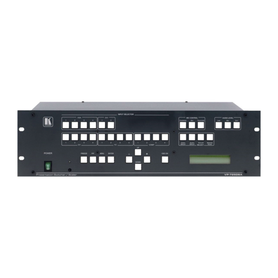
Your VP-725DSA Presentation Switcher / Scaler Figure 1 and Table 1 define the front panel of the VP-725DSA: 1 The VP725 Text Overlay Application (Text Overlay Sender) for the VP-725DSA (and the VP-725DS) can be downloaded at http://www.kramerelectronics.com 2 See section 7.4... -
Page 12: Figure 1: Vp-725Dsa Presentation Switcher / Scaler Front Panel
SCALER MASTER GROUP GROUP COMP AUDIO SELECT FREEZE ENTER OSD ON DOWN MIC CONTROL AUDIO LEVEL LINE OVERRIDE TALKOVER VIDEO AUDIO SCALER MASTER GROUP GROUP AUDIO SELECT Figure 1: VP-725DSA Presentation Switcher / Scaler Front Panel KRAMER: SIMPLE CREATIVE TECHNOLOGY... -
Page 13: Table 1: Front Panel Vp-725Dsa Presentation Switcher / Scaler Features
Your VP-725DSA Presentation Switcher / Scaler Table 1: Front Panel VP-725DSA Presentation Switcher / Scaler Features Feature Function VGA Button Selects one of the 4 VGA sources DVI Button Selects one of the 2 DVI sources CV Button Selects one of the 4 CV sources... - Page 14 MASTER OUT terminal block connector Figure 2 and Table 2 define the rear panel of the VP-725DSA: 1 Only one of the three buttons can be ON, or all three buttons can be OFF (pressing a button will select that button, and turn OFF the previously selected button.
-
Page 15: Figure 2: Vp-725Dsa Presentation Switcher / Scaler Rear Panel
IN 4 IN 2 IN 4 G/Y2 B/Pb2 R/Pr2 G/Y4 B/Pb4 R/Pr4 SCALED OUTPUTS IN 1 IN 3 90-264 VAC IN 1 IN 2 50/60 Hz IN 2 IN 4 R/Pr B/Pb Figure 2: VP-725DSA Presentation Switcher / Scaler Rear Panel... -
Page 16: Table 2: Rear Panel Vp-725Dsa Presentation Switcher / Scaler Features
Your VP-725DSA Presentation Switcher / Scaler Table 2: Rear Panel VP-725DSA Presentation Switcher / Scaler Features Feature Function CV Connector Connects the balanced audio acceptor (for composite) YC Connector Connects the balanced audio acceptor (for s-Video) VGA Connector Connects the balanced audio acceptor (for VGA) -
Page 17: Installing On A Rack
The machine is earthed (grounded) in a reliable way If you are using a Kramer rack and is connected only to an electricity socket with adapter kit (for a machine that is not grounding. -
Page 18: Connecting The Vp-725Dsa Presentation Switcher / Scaler
Source 1 and DVI Source 2 to the DVI connectors 1 Switch OFF the power on each device before connecting it to your VP-725DSA. After connecting your VP-725DSA, switch on its power and then switch on the power on each device... - Page 19 Connecting the VP-725DSA Presentation Switcher / Scaler 2. Connect one or more of the following balanced stereo audio sources (not illustrated in Figure 3). In particular, the audio of: VGA Sources 1, 2, 3 and 4 to the AUDIO input terminal block...
- Page 20 Connecting the VP-725DSA Presentation Switcher / Scaler Figure 3: Connecting the VP-725DSA Presentation Switcher / Scaler KRAMER: SIMPLE CREATIVE TECHNOLOGY...
-
Page 21: Connecting The Master Out Terminal Block Connector
Connecting the VP-725DSA Presentation Switcher / Scaler Connecting the MASTER OUT Terminal Block Connector The MASTER OUT terminal block connector can be used in the Master Audio Mode (see section 6.1.1) and the Master AV Mode (see section 6.1.2). 6.1.1... -
Page 22: The Rgbs And Rgsb Pinouts
Red to Pr Connecting a PC You can connect a PC (or other controller) to the VP-725DSA via the RS-232 port for remote control, and for upgrading the firmware. To connect a PC to a VP-725DSA unit, using the Null-modem adapter... -
Page 23: Connecting The Vp-725Dsa Via The Ethernet Port
6.4.1 Connecting the ETHERNET Port directly to a PC (Crossover Cable) You can connect the Ethernet port of the VP-725DSA to the Ethernet port on your PC, via a crossover cable with RJ-45 connectors, as Table 4 and Figure 7 define. -
Page 24: Figure 8: Local Area Connection Properties Window
Connecting the VP-725DSA Presentation Switcher / Scaler 4. Select Internet Protocol (TCP/IP) and click the Properties Button (see Figure 8). Figure 8: Local Area Connection Properties Window 5. Select Use the following IP Address , and fill in the details as shown in Figure 9. -
Page 25: Connecting The Ethernet Port Via A Network Hub (Straight-Through Cable)
Connecting the ETHERNET Port via a Network Hub (Straight-Through Cable) You can connect the Ethernet port of the VP-725DSA to the Ethernet port on a network hub or network router, via a straight-through cable with RJ-45 connectors, as Table 5 defines:... -
Page 26: Connecting The Balanced/Unbalanced Stereo Audio Input/Output
Connecting the VP-725DSA Presentation Switcher / Scaler Connecting the Balanced/Unbalanced Stereo Audio Input/Output Figure 10, Figure 11, and Figure 12 illustrate how to wire a balanced/unbalanced input and/or output connection: L+ L- G R+ R- Figure 10: Connecting a Balanced Stereo Audio Input/Output... -
Page 27: Understanding The Presentation Switcher / Scaler
Video Groups: composite video, s-Video, component video (RGB or YPbPr), DVI-D and VGA. When the VP-725DSA is in use, both modes operate simultaneously, as well as independently. That is, the Scaler output is available even when switching... -
Page 28: Understanding The Audio Features
1 By pressing the Audio Level key on the infra-red remote control transmitter (see Figure 55). This also cycles between the front panel AUDIO LEVEL buttons: Out, Line, and Mic. The selected AUDIO LEVEL may also be adjusted by pressing the + and – buttons on the front panel KRAMER: SIMPLE CREATIVE TECHNOLOGY... -
Page 29: Adjusting The Audio Level
Understanding the Presentation Switcher / Scaler 7.3.2 Adjusting the Audio Level You can set the audio level to determine the volume for each Group input and output, as well as for the Master In, Master Out, and Mic In (see Table 13). To adjust the group audio level via the front panel: 1. -
Page 30: Understanding The Pip Button Feature
8 By default, 20 seconds. But you can reset the timeout (from 3 to 60 seconds), see section 9.1.5.7 9 Trying to activate the PIP again while the PIP is still enclosed by an orange frame deactivates the PIP KRAMER: SIMPLE CREATIVE TECHNOLOGY... -
Page 31: Pip Characteristics
Understanding the Presentation Switcher / Scaler Figure 13: OSD PIP Status When the Source Prompt is OFF, activating the PIP toggles between the PIP (with no frame and no OSD PIP status) and no PIP. 7.4.2 PIP Characteristics You can determine the following PIP characteristics: PIP Source PIP Size (1/25, 1/16, 1/9, 1/4, or split screen) Horizontal and Vertical position, placing it anywhere on the screen... -
Page 32: Resizing The Pip
When the Source Prompt is OFF (or ON, but without the orange frame), use the four navigation control keys on the infra-red remote control transmitter (see Figure 55), or the UP, DOWN, + and/or – front panel OSD buttons KRAMER: SIMPLE CREATIVE TECHNOLOGY... -
Page 33: Locking And Unlocking The Front Panel
Understanding the Presentation Switcher / Scaler Locking and Unlocking the Front Panel To prevent accidental changes to settings or unauthorized tampering with the front panel, you can lock the front panel. This disengages the front panel switches except for the MENU button on the front panel (press and hold for 3 seconds to unlock). -
Page 34: Operating The Presentation Switcher / Scaler
1 For glitchless transitions between inputs 2 To set the image transition speed (fast, moderate or safe), see section 9.1.5.6 3 By default, 20 seconds. But you can reset the timeout (from 3 to 60 seconds), see section 9.1.5.7 KRAMER: SIMPLE CREATIVE TECHNOLOGY... -
Page 35: Displaying A Blank Screen
Operating the Presentation Switcher / Scaler Pressing the appropriate illuminated INPUT SELECTOR front panel button or the appropriate INPUT SELECTOR key on the infra-red remote control transmitter (see Figure 55) The image freezes. The FREEZE front panel button illuminates and the appropriate INPUT SELECTOR button flashes. -
Page 36: Choosing The Output Resolution
1 By default, 20 seconds. But you can reset the timeout (from 3 to 60 seconds), see section 9.1.5.7 2 Adjusting the output resolution results in a corresponding adjustment to the size of the OSD status window KRAMER: SIMPLE CREATIVE TECHNOLOGY... -
Page 37: Controlling The Vp-725Dsa Presentation Switcher / Scaler
Operating via the OSD MENU Screen The OSD superimposes a menu on the screen from which you can control your VP-725DSA. When the OSD ON front panel button is selected, pressing the MENU front panel OSD button or the MENU key on the infra-red remote control transmitter (see Figure 55) displays the first OSD screen, the “Brightness and Contrast”... -
Page 38: Controlling The Brightness And Contrast
Controlling the VP-725DSA Presentation Switcher / Scaler Figure 19 defines the six interactive icons Brightness Gamma Geometry Utility Information Source and Color Contrast Figure 19: Menu Screen Icons 9.1.1 Controlling the Brightness and Contrast Figure 18 and Table 6 define the Brightness and Contrast Screen:... -
Page 39: Selecting The Source
Controlling the VP-725DSA Presentation Switcher / Scaler Table 7: Controlling the Gamma and Color Gamma and Color Level 1 Level 2 Range Default Normal Presentation Cinema Nature User 1 / 2 Gamma -10 to 10 Color Temperature 0 to 127... -
Page 40: Figure 23: Selecting The Search
Controlling the VP-725DSA Presentation Switcher / Scaler Table 8: Selecting the Source Source Level 1 Level 2 Level 3 Search Manual Auto Select Video Group Audio Group AV Group Scaler Master Audio Master AV Source VGA Group VGA1 VGA2 VGA3... -
Page 41: Figure 24: Selecting The Group
Controlling the VP-725DSA Presentation Switcher / Scaler Selecting Manual Search disables the Auto Search option (which finds the active source). After powering up, the VP-725DSA will not scan for an active input but will display the source selected prior to power down, even if that input is inactive. -
Page 42: Controlling The Geometry
Controlling the VP-725DSA Presentation Switcher / Scaler 9.1.4 Controlling the Geometry Figure 26 and Table 9 define the main Geometry Screen, from which you can choose the aspect ratio, zoom, and set the keystone angle: Figure 26: Geometry Screen Table 9: Controlling the Geometry... -
Page 43: Figure 27: Geometry (Aspect Ratio) Screen
Controlling the VP-725DSA Presentation Switcher / Scaler Figure 27 illustrates the Geometry (Aspect Ratio) Screen. You can set the following characteristics according to your specific requirements: anamorphic (displays the aspect ratio (usually 16:9)), virtual wide (anamorphic plus non-linear scaling), letterbox (the vertical line is expanded to full screen —... -
Page 44: Figure 29: Osd Enlarge Status
Controlling the VP-725DSA Presentation Switcher / Scaler Figure 29: OSD Enlarge Status When you change the zoom ratio or zoom position, the screen image is adjusted correspondingly, and the change is reflected in the pop-up OSD Enlarge status box. For example, Figure 30 illustrates a zoom ratio increase... -
Page 45: Adjusting The Zoom Ratio
Controlling the VP-725DSA Presentation Switcher / Scaler 9.1.4.1 Adjusting the Zoom Ratio You can adjust the zoom ratio to up to 400% via one or both of these methods: Using the Zoom + and/or the Zoom - control keys on the infra-red remote control transmitter (see Figure 55). -
Page 46: Configuring Via The Utility Screens
Figure 34: Geometry (Keystone) Screen 9.1.5 Configuring via the Utility Screens You can determine how your VP-725DSA will function either generally or on a specific occasion, via the Utility screen settings (see Figure 35): Figure 35: Utility Screen KRAMER: SIMPLE CREATIVE TECHNOLOGY... -
Page 47: Choosing The Graphic Utility Settings
Controlling the VP-725DSA Presentation Switcher / Scaler 9.1.5.1 Choosing the Graphic Utility Settings Figure 36 and Table 10 define the Graphic Setting Utility screen. You can set the color format (see Figure 37), position, color, hue, sharpness, frequency and phase, as well as auto image... -
Page 48: Choosing The Video Utility Settings
Controlling the VP-725DSA Presentation Switcher / Scaler Figure 37: Graphic Setting Color Format Utility Screen 9.1.5.2 Choosing the Video Utility Settings Figure 38 and Table 11 define the Video Setting Utility screen. You can set the Color Format, Standard (see Figure 39), color, hue, sharpness, and position. -
Page 49: Choosing The Audio Utility Settings
Controlling the VP-725DSA Presentation Switcher / Scaler Table 11: Choosing the Video Utility Settings Utility Level 1 Level 2 Level 3 Level 4 Range Default Color Format Default Video Setting Standard Auto Auto NTSC NTSC4.43 PAL-N PAL-M SECAM Color 0 to 128... -
Page 50: Choosing The Audio Level Utility Settings
Controlling the VP-725DSA Presentation Switcher / Scaler 9.1.5.4 Choosing the Audio Level Utility Settings Figure 41 and Table 13 define the Audio Level Utility screen Figure 41: Choosing the Audio Level Settings Table 13: Choosing the Audio Level Settings Utility... -
Page 51: Choosing The Pip Utility Settings
Controlling the VP-725DSA Presentation Switcher / Scaler 9.1.5.5 Choosing the PIP Utility Settings Figure 42 and Table 14 define the PIP Setting Utility screen. You can activate the PIP, choose the source, the size, and the position of the PIP. -
Page 52: Choosing The Seamless Switch Utility Settings
Controlling the VP-725DSA Presentation Switcher / Scaler 9.1.5.6 Choosing the Seamless Switch Utility Settings Figure 43 and Table 15 define the Seamless Switch Utility screen. You can choose the image transition speed Mode Figure 43: Choosing the Seamless Switch Utility Settings... -
Page 53: Choosing The Osd Utility Settings
Controlling the VP-725DSA Presentation Switcher / Scaler 9.1.5.7 Choosing the OSD Utility Settings Figure 44 and Table 16 define the OSD Setting Utility screen. You can set the OSD position, time out, size (see Figure 45), source prompt , and choose the blank color (blue or black - see Figure 46). -
Page 54: Choosing The Output Utility Settings
Controlling the VP-725DSA Presentation Switcher / Scaler Figure 46: OSD Blank Color Utility Screen 9.1.5.8 Choosing the Output Utility Settings Figure 47 and Table 17 define the Output Setting Utility screen. You can set the resolution (see Figure 48), refresh rate (see Figure 49), color format, and a user definable output mode (see Figure 50 and Table 18). -
Page 55: Figure 48: Output Setting Resolution Utility Screen
Controlling the VP-725DSA Presentation Switcher / Scaler Table 17: Choosing the Output Utility Settings Utility Level 1 Level 2 Level 3 Output Setting Resolution 640x480 1280x720 832x624 800x600 720x483 1024x800 1024x768 852x480 1152x864 1280x1024 1400x1050 1152x870 1600x1200 480P 1152x900 852x1024i... -
Page 56: Choosing Factory Reset
Controlling the VP-725DSA Presentation Switcher / Scaler Figure 50: Output Setting User Mode Setting Utility Screen Table 18: User Mode Setting Definitions User Mode Setting Definitions Horizontal total Horizontal sync pulse width Horizontal active start point Horizontal active region Horizontal polarity... -
Page 57: Choosing Advanced Utility Settings
Controlling the VP-725DSA Presentation Switcher / Scaler 9.1.5.10 Choosing Advanced Utility Settings Figure 52 and Table 19 define the Advanced Utility screen. Figure 52: Advanced Utility Screen Table 19: Advanced Utility Screen Features Button Function Input Button You can set the function of the input button besides selecting the input... -
Page 58: Verifying Configuration Details Via The Information Screen
Controlling the VP-725DSA Presentation Switcher / Scaler 9.1.6 Verifying Configuration Details via the Information Screen From the Information screen (see Figure 53), you can verify information that includes: the main source, the PIP source, the output mode, as well as the unit’s firmware versions:... -
Page 59: Operating Via The Lcd Display
Keystone to 6 via the LCD Display, using the front panel buttons, do the following: 1. Turn the VP-725DSA unit ON, and press the OSD ON button (if selected). 2. Press the appropriate front panel OSD buttons (as defined in Figure 54). -
Page 60: Figure 55: Infra-Red Remote Control Transmitter
Controlling the VP-725DSA Presentation Switcher / Scaler Figure 55: Infra-red Remote Control Transmitter KRAMER: SIMPLE CREATIVE TECHNOLOGY... -
Page 61: Table 21: Infra-Red Remote Control Transmitter Functions
Controlling the VP-725DSA Presentation Switcher / Scaler Table 21: Infra-Red Remote Control Transmitter Functions Keys Function FREEZE Freezes the output video image Activates/deactivates access to the OSD Menu POWER Cycles power INPUT 18 separate keys for selecting these sources: AV1, AV2, AV3, AV4; COMP1, COMP2, SELECTOR COMP3, COMP4;... -
Page 62: Operating Via Ethernet/Serial Port
Figure 56: VP725 Ethernet Application Main Dialog Box (Configuration Tab) 1 Or connect the serial port of your VP-725DSA to the serial port of your PC (see section 6.2) 2 Or download the software from our Web site on http://www.kramerelectronics.com... -
Page 63: Figure 57: Vp725 Ethernet Application Search Panel Screen
Controlling the VP-725DSA Presentation Switcher / Scaler Table 22: VP725 Ethernet Application Configuration Tab Button Function Autoscan Press to automatically scan for connected machines Press to scroll down the Server list Down Press to scroll up the Server list Delete... -
Page 64: Control The Vp-725Dsa Via The Ethernet/Serial Port
Figure 59: Setting an IP Number 9.4.3 Control the VP-725DSA via the Ethernet/Serial Port To control the VP-725DSA via the Ethernet, do the following: 1. On the VP725 Ethernet Application screen, click the Control tab. The Control screen appears (see Figure 60). -
Page 65: Figure 60: Vp725 Ethernet Application Main Dialog Box (Control Tab)
Controlling the VP-725DSA Presentation Switcher / Scaler Figure 60: VP725 Ethernet Application Main Dialog Box (Control Tab) The Control tab includes: The front panel buttons The BLANK, SWAP, MUTE and KEYLOCK buttons, which appear only on the remote control transmitter... -
Page 66: 10 Using Text Overlay
10 Using Text Overlay The text overlay feature is accessed via the Application Program (AP) Running this AP with the PC connected to the VP-725DSA lets you display text over the screen, with a rich feature set including text color and speed, transparency, text position and repetition. -
Page 67: Table 23: Features And Functions Of The Textoverlay Application
TCP/IP Check box When selected, set the IP Address and Port to connect via Ethernet RS-232 Check box When selected, set the COM port and Baud Rate (9600 for VP-725DSA) to connect via the RS-232 connector VP725 Check box Select VP725 when connected to a VP-725 series machine... -
Page 68: 10.1 Downloading The Textoverlay Program
Select the Number of Buffer and the Display Height Set the V-Position Set the Blank Time and the scrolling Speed Set the Mode to Static or Scrolling If in the Static mode, set the text H – Offset 1 Go to http://www.kramerelectronics.com KRAMER: SIMPLE CREATIVE TECHNOLOGY... -
Page 69: Connecting And Disconnecting The Textoverlay Program
Using Text Overlay If required, select the Buffer option (0 to 2) to send varying text messages Select the Repeating frequency (1 to 20 or Forever) Select the Font and Font size Table 25 describes when the setup parameters are available: Table 25: TextOverlay Parameters The Parameter Before “Start to... -
Page 70: Saving And Loading Settings
You can save current settings at any time or load a previously saved setting. When loading a setting , the TextOverlay program automatically disconnects and you need to reconnect it. 1 A saved setting also includes the connection type (TCP/IP or RS-232) KRAMER: SIMPLE CREATIVE TECHNOLOGY... -
Page 71: 11 Technical Specifications
11 Technical Specifications Table 26 includes the technical specifications: Table 26: Technical Specifications of the VP-725DSA Presentation Switcher / Scaler INPUTS: 4 x CV 1Vpp/75 on BNC connectors; 4 x YC 1Vpp (Y); 0.3Vpp (C)/75 on 4p connectors; 4 x Component (Y/G, Pb/B, Pr/R or RGsB ) on BNC connectors;... -
Page 72: 12 Vp-725Dsa Communication Protocol
After set type Command setting, system will respond a string as “ Done” . The default data rate is 9600 Baud, with no parity, 8 data bits and 1 stop bit. Table 27 includes the Communication Protocol: Table 27: Communication Protocol of the VP-725DS/VP-725DSA Control Type Function... - Page 73 VP-725DSA Communication Protocol Control Type Function Param (for Set) Function Description Comment COMP1 COMP2 COMP3 COMP4 VGA1 VGA2 VGA3 VGA4 DVI1 DVI2 Override VP-725DSA only VP-725DSA only TalkOver VP-725DSA only SELECT Video Group Audio Group VP-725DSA only Scaler Master Audio...
- Page 74 VP-725DSA Communication Protocol Control Type Function Param (for Set) Function Description Comment 1: Set -32~32 H-Pan 2: Get 1: Set -32~32 V-Pan 2: Get 1: Set -32~32 Keystone Angle 2: Get 1: Set 0~255 Graphics H-Position 2: Get 1: Set...
- Page 75 VP-725DSA Communication Protocol Control Type Function Param (for Set) Function Description Comment Audio Level: Master Output Level 1: Set 0~255 VP-725DSA only 2: Get 1: Set 0~255 Audio Level: Mic Input Level VP-725DSA only 2: Get 1: Set 0~36 PIP Setting: PIP H-Position...
- Page 76 VP-725DSA Communication Protocol Control Type Function Param (for Set) Function Description Comment 1: Set Gamma and Color: User1Color Temp 0~127 2: Get Blue 1: Set Gamma and Color: User1Color Manager 0~32 2: Get 1: Set Gamma and Color: User1Color Manager...
- Page 77 VP-725DSA Communication Protocol Control Type Function Param (for Set) Function Description Comment 3: Set Video Setting: 0: Default 1: RGB 2: YUV 4: Get Color Format 0: Video Standard - Auto 1: Video Standard - NTSC 2: Video Standard - NTSC 4.43...
- Page 78 VP-725DSA Communication Protocol Control Type Function Param (for Set) Function Description Comment Gamma/Color - User 2 Aspect Ratio - Anamorphic Aspect Ratio - Virtual Wide Aspect Ratio - Letterbox Aspect Ratio - Native Aspect Ratio - 4:3 Output Aspect Ratio -...
-
Page 79: 13 Vp-725Dsa Text Overlay Protocol
VP-725DSA Text Overlay Protocol 13 VP-725DSA Text Overlay Protocol Table 28 includes the Text Overlay Protocol. Command P1 P2 P3; P1, 2, 3: Parameters 1, 2, 3 Table 28: Text Overlay Protocol of the VP-725DSA Functions Command Comments Display Buffer T12ED ** ** ** Page No. - Page 80 EXCLUSION OF DAMAGES The liability of Kramer for any effective products is limited to the repair or replacement of the product at our option. Kramer shall not be liable for: Damage to other property caused by defects in this product, damages based upon inconvenience, loss of use of the product, loss of time, commercial loss;...
- Page 81 For the latest information on our products and a list of Kramer distributors, visit our Web site: www.kramerelectronics.com, where updates to this user manual may be found. We welcome your questions, comments and feedback. Safety Warning: Disconnect the unit from the power supply before opening/servicing.
Need help?
Do you have a question about the VP-725DSA and is the answer not in the manual?
Questions and answers