Sign In
Upload
Manuals
Brands
Kramer Manuals
Switch
VP-725DSA
Kramer VP-725DSA Manuals
Manuals and User Guides for Kramer VP-725DSA. We have
1
Kramer VP-725DSA manual available for free PDF download: User Manual
Kramer VP-725DSA User Manual (81 pages)
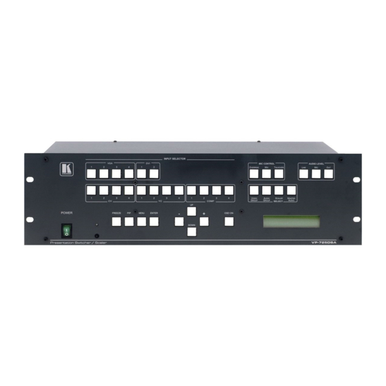
Presentation Switcher / Scaler
Brand:
Kramer
| Category:
Switch
| Size: 3 MB
Table of Contents
User Manual
1
Table of Contents
2
1 Introduction
7
2 Getting Started
7
Quick Start
7
3 Overview
9
4 Your VP-725DSA Presentation Switcher / Scaler
11
Figure 1: VP-725DSA Presentation Switcher / Scaler Front Panel
12
Table 1: Front Panel VP-725DSA Presentation Switcher / Scaler Features
13
Figure 2: VP-725DSA Presentation Switcher / Scaler Rear Panel
15
Table 2: Rear Panel VP-725DSA Presentation Switcher / Scaler Features
16
5 Installing on a Rack
17
6 Connecting the VP-725DSA Presentation Switcher / Scaler
18
Connecting the MASTER out Terminal Block Connector
21
Using the MASTER out in the Master Audio Mode
21
Using the MASTER out in the Master AV Mode
21
Figure 3: Connecting the VP-725DSA Presentation Switcher / Scaler
21
Figure 4: Connecting the MASTER out (in Master Audio Mode)
21
Figure 5: Connecting the MASTER out (in Master AV Mode)
21
The RGBS and Rgsb Pinouts
22
Connecting a PC
22
Figure 6: Connecting the PC
22
Table 3: RGBS and Rgsb PINOUTS
22
Connecting the VP-725DSA Via the ETHERNET Port
23
Connecting the ETHERNET Port Directly to a PC (Crossover Cable)
23
Figure 7: RJ-45 PINOUT
23
Table 4: Crossover Cable RJ-45 PINOUT
23
Figure 8: Local Area Connection Properties Window
24
Figure 9: Internet Protocol (TCP/IP) Properties Window
24
Connecting the ETHERNET Port Via a Network Hub (Straight-Through Cable)
25
Table 5: Straight-Through Cable RJ-45 PINOUT
25
Connecting the Balanced/Unbalanced Stereo Audio Input/Output
26
Figure 10: Connecting a Balanced Stereo Audio Input/Output
26
Figure 11: Connecting an Unbalanced Stereo Audio Input
26
Figure 12: Connecting an Unbalanced Stereo Audio Output
26
7 Understanding the Presentation Switcher / Scaler
27
Understanding the Video Group Mode/Scaler Mode
27
Understanding the Audio Group Mode/Master Audio Group Mode
27
Understanding the Audio Features
28
Choosing Audio-Follow-Video or Audio Breakaway
28
Adjusting the Audio Level
29
Using the Microphone CONTROL Modes
29
Understanding the PIP Button Feature
30
Activating the PIP Feature
30
PIP Characteristics
31
Toggling between the PIP and the Screen Source (SWAP)
31
Figure 13: OSD PIP Status
31
Figure 14: OSD SWAP Status
31
Resizing the PIP
32
Moving the Position of the PIP
32
Locking and Unlocking the Front Panel
33
Figure 15: Locking / Unlocking the Front Panel
33
8 Operating the Presentation Switcher / Scaler
34
Switching an Input
34
Freezing the Image
34
Figure 16: OSD Input Status
34
Displaying a Blank Screen
35
Choosing the Output Resolution
36
Figure 17: OSD Output Status
36
9 Controlling the VP-725DSA Presentation Switcher / Scaler
37
Operating Via the OSD MENU Screen
37
Figure 18: Controlling the Brightness and Contrast
37
Controlling the Brightness and Contrast
38
Controlling the Gamma and Color
38
Figure 19: Menu Screen Icons
38
Figure 20: Controlling the Gamma and Color
38
Table 6: Controlling the Brightness and Contrast
38
Selecting the Source
39
Figure 21: Gamma, Color Temperature/Manager User 1/2 Screen
39
Figure 22: Selecting the Source
39
Table 7: Controlling the Gamma and Color
39
Figure 23: Selecting the Search
40
Table 8: Selecting the Source
40
Figure 24: Selecting the Group
41
Figure 25: Selecting the Source
41
Controlling the Geometry
42
Figure 26: Geometry Screen
42
Table 9: Controlling the Geometry
42
Figure 27: Geometry (Aspect Ratio) Screen
43
Figure 28: Geometry (Zoom) Screen
43
Figure 29: OSD Enlarge Status
44
Figure 30: Zoom Ratio Adjustment Example
44
Figure 31: Zoom Position Adjustment Example
44
Adjusting the Zoom Ratio
45
Adjusting the Zoom Position
45
Figure 32: Geometry (Zoom Ratio) Screen
45
Configuring Via the Utility Screens
46
Figure 33: Geometry (Zoom Position Adjustment) Screen
46
Figure 34: Geometry (Keystone) Screen
46
Figure 35: Utility Screen
46
Choosing the Graphic Utility Settings
47
Figure 36: Choosing the Graphic Utility Settings
47
Table 10: Choosing the Graphic Utility Settings
47
Choosing the Video Utility Settings
48
Figure 37: Graphic Setting Color Format Utility Screen
48
Figure 38: Choosing the Video Utility Settings
48
Figure 39: Video Setting Standard Utility Screen
48
Choosing the Audio Utility Settings
49
Figure 40: Choosing the Audio Utility Settings
49
Table 11: Choosing the Video Utility Settings
49
Table 12: Choosing the Audio Utility Settings
49
Choosing the Audio Level Utility Settings
50
Figure 41: Choosing the Audio Level Settings
50
Table 13: Choosing the Audio Level Settings
50
Choosing the PIP Utility Settings
51
Figure 42: Choosing the PIP Utility Settings
51
Table 14: Choosing the PIP Utility Settings
51
Choosing the Seamless Switch Utility Settings
52
Figure 43: Choosing the Seamless Switch Utility Settings
52
Table 15: Choosing the Seamless Switch Utility Settings
52
Choosing the OSD Utility Settings
53
Figure 44: Choosing the OSD Utility Settings
53
Figure 45: OSD Size Utility Screen
53
Table 16: Choosing the OSD Utility Settings
53
Choosing the Output Utility Settings
54
Figure 46: OSD Blank Color Utility Screen
54
Figure 47: Choosing the Output Utility Settings
54
Figure 48: Output Setting Resolution Utility Screen
55
Figure 49: Output Setting Refresh Rate Utility Screen
55
Table 17: Choosing the Output Utility Settings
55
Choosing Factory Reset
56
Figure 50: Output Setting User Mode Setting Utility Screen
56
Figure 51: Factory Reset Utility Screen
56
Table 18: User Mode Setting Definitions
56
Choosing Advanced Utility Settings
57
Figure 52: Advanced Utility Screen
57
Table 19: Advanced Utility Screen Features
57
Table 20: User Define Measure Features
57
Verifying Configuration Details Via the Information Screen
58
Figure 53: Information Screen
58
Operating Via the LCD Display
59
Operating Via the Infra-Red Remote Control Transmitter
59
Figure 54: Example of How to Use the LCD Display
59
Figure 55: Infra-Red Remote Control Transmitter
60
Table 21: Infra-Red Remote Control Transmitter Functions
61
Operating Via Ethernet/Serial Port
62
Installing and Running the Configuration Software
62
Configuring the Ethernet Connection
62
The Configuration Screen
62
Figure 56: VP725 Ethernet Application Main Dialog Box (Configuration Tab)
62
Figure 57: VP725 Ethernet Application Search Panel Screen
63
Figure 58: Configuration Tab
63
Table 22: VP725 Ethernet Application Configuration Tab
63
Control the VP-725DSA Via the Ethernet/Serial Port
64
Figure 59: Setting an IP Number
64
Figure 60: VP725 Ethernet Application Main Dialog Box (Control Tab)
65
10 Using Text Overlay
66
Figure 61: Textoverlay Application Screen
66
Table 23: Features and Functions of the Textoverlay Application
67
10.1 Downloading the Textoverlay Program
68
10.2 Setting the Text Message
68
Table 24: Number of Buffers, Output Resolution and Maximum Display Height
68
Connecting and Disconnecting the Textoverlay Program
69
Table 25: Textoverlay Parameters
69
Saving and Loading Settings
70
11 Technical Specifications
71
Table 26: Technical Specifications of the VP-725DSA Presentation Switcher / Scaler
71
12 VP-725DSA Communication Protocol
72
Table 27: Communication Protocol of the VP-725DS/VP-725DSA
72
13 VP-725DSA Text Overlay Protocol
79
Table 28: Text Overlay Protocol of the VP-725DSA
79
Advertisement
Advertisement
Related Products
Kramer VP-725NA
Kramer VP-725XLA
Kramer VP-725xl
Kramer VP-725N
Kramer VP-724x1
Kramer VP-723x1
Kramer ProScale VP-728
Kramer VP-727A
Kramer VP-727A-BA
Kramer VP-724xl
Kramer Categories
Matrix Switcher
Switch
Media Converter
Amplifier
Receiver
More Kramer Manuals
Login
Sign In
OR
Sign in with Facebook
Sign in with Google
Upload manual
Upload from disk
Upload from URL