Cisco ASA 5505 Hardware Installation Manual
Adaptive security appliance
Hide thumbs
Also See for ASA 5505:
- Configuration manual (1822 pages) ,
- Getting started manual (168 pages) ,
- Administrator's manual (118 pages)
Table of Contents
Advertisement
Quick Links
Cisco ASA 5505 Adaptive Security
Appliance Hardware Installation Guide
Americas Headquarters
Cisco Systems, Inc.
170 West Tasman Drive
San Jose, CA 95134-1706
USA
http://www.cisco.com
Tel: 408 526-4000
800 553-NETS (6387)
Fax: 408 527-0883
Customer Order Number: OL-18362-01
Text Part Number: OL-18362-01
Advertisement
Table of Contents

Related Manuals for Cisco ASA 5505


Summary of Contents for Cisco ASA 5505
- Page 1 Cisco ASA 5505 Adaptive Security Appliance Hardware Installation Guide Americas Headquarters Cisco Systems, Inc. 170 West Tasman Drive San Jose, CA 95134-1706 http://www.cisco.com Tel: 408 526-4000 800 553-NETS (6387) Fax: 408 527-0883 Customer Order Number: OL-18362-01 Text Part Number: OL-18362-01...
- Page 2 You can determine whether your equipment is causing interference by turning it off. If the interference stops, it was probably caused by the Cisco equipment or one of its peripheral devices. If the equipment causes interference to radio or television reception, try to correct the interference by using one or more of the following measures: •...
-
Page 3: Table Of Contents
C H A P T E R Installing the Chassis Connecting the Interface Cables Powering on the Cisco ASA 5505 Installing a Cable Lock Rack or Wall Mounting the Cisco ASA 5505 Mounting the Chassis Wall-Mounting the Chassis Cisco ASA 5505 Hardware Installation Guide OL-18362-01... - Page 4 Contents Rack-Mounting the Chassis Installing and Wall-Mounting the Cisco ASA 5505 FIPS Enclosure 3-11 Maintenance and Upgrade Procedures C H A P T E R Removing and Replacing the Chassis Cover Working in an ESD Environment Removing the Chassis Cover...
-
Page 5: About This Guide
• Obtaining Documentation and Submitting a Service Request, page x Document Objectives This guide describes how to perform installation and maintenance procedures on the Cisco ASA 5505 Adaptive Security Appliance. Audience This guide is for network administrators who perform any of the following tasks: Managing network security •... -
Page 6: Document Conventions
Installation Warnings Be sure to read the Regulatory Compliance and Safety Information for the Cisco ASA 5500 Series document that accompanied this device before installing the chassis. This document contains important safety information. This section includes the following warnings: Power Supply Disconnection Warning, page vii •... - Page 7 Do not work on the system or connect or disconnect cables during periods of lightning activity. Warning Statement 1001 Installation Instructions Warning Read the installation instructions before connecting the system to the power source. Statement 1004 Warning Cisco ASA 5505 Adaptive Security Appliance Hardware Installation Guide OL-18362-01...
- Page 8 Statement 1029 Product Disposal Warning Ultimate disposal of this product should be handled according to all national laws and regulations. Warning Statement 1040 Cisco ASA 5505 Adaptive Security Appliance Hardware Installation Guide viii OL-18362-01...
- Page 9 This product relies on the building’s installation for short-circuit (overcurrent) protection. Ensure that Warning a fuse or circuit breaker no larger than 120 VAC, 15A U.S. (240 VAC, 10A international) is used on the phase conductors (all current-carrying conductors). Statement 13 Cisco ASA 5505 Adaptive Security Appliance Hardware Installation Guide OL-18362-01...
-
Page 10: Where To Find Safety And Warning Information
Obtaining Documentation and Submitting a Service Request For information on obtaining documentation, submitting a service request, and gathering additional information, see the monthly What’s New in Cisco Product Documentation, which also lists all new and revised Cisco technical documentation, at: http://www.cisco.com/en/US/docs/general/whatsnew/whatsnew.html... -
Page 11: Chapter 1 Overview
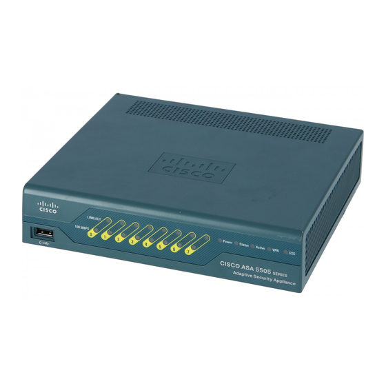
Only trained and qualified personnel should install, replace, or service this equipment Statement 49 Read the safety warnings in the Regulatory Compliance and Safety Information for the Cisco ASA 5500 Caution Series and follow proper safety procedures when performing these steps. - Page 12 1. Ports 6 and 7 are 15-Watt output PoE ports, used for devices, such as IP phones, which can be powered by the network interface. They can also be used as regular Ethernet switch ports, just like the ports numbered 0 through 5. Cisco ASA 5505 Adaptive Security Appliance Hardware Installation Guide OL-18362-01...
-
Page 13: Memory Requirements
Flash memory to the unit with the smaller Flash memory will fail. For more information, see the Cisco Security Appliance Command Line Configuration Guide. Memory Requirements for the Software Version 8.3 and Later For information on memory requirements for the adaptive security appliance for software Version 8.3 or... - Page 14 Chapter 1 Overview Memory Requirements Cisco ASA 5505 Adaptive Security Appliance Hardware Installation Guide OL-18362-01...
-
Page 15: Chapter 2 Preparing For Installation
C H A P T E R Preparing for Installation The information in this guide applies to the Cisco ASA 5505 In this guide, references to “adaptive security appliance” or security appliance apply to the Cisco ASA 5505 chassis unless specifically noted otherwise. -
Page 16: Maintaining Safety With Electricity
Install the adaptive security appliance in compliance with local and national electrical codes as listed • in the Regulatory Compliance and Safety Information for the Cisco ASA 5500 Series document. The adaptive security appliance models equipped with AC-input power supplies are shipped with a •... -
Page 17: Preventing Electrostatic Discharge Damage
Preventive Site Configuration The following precautions will help plan an acceptable operating environment for the chassis and avoid environmentally caused equipment failures: Cisco ASA 5505 Adaptive Security Appliance Hardware Installation Guide OL-18362-01... -
Page 18: Power Supply Considerations
Install proper site grounding facilities to guard against damage from lightning or power surges. Configuring Equipment Racks For information on physical specifications, see table 7 at the following url: http://www.cisco.com/en/US/prod/collateral/vpndevc/ps6032/ps6094/ps6120/product_data_sheet0900a ecd802930c5.html. Cisco ASA 5505 Adaptive Security Appliance Hardware Installation Guide OL-18362-01... -
Page 19: Chapter 3 Installing The Cisco Asa 5505
Only trained and qualified personnel should install, replace, or service this equipment Statement 49 Warning Read the safety warnings in the Regulatory Compliance and Safety Information for the Cisco ASA 5505 Caution Adaptive Security Appliance and follow proper safety procedures when performing these steps. - Page 20 If you are connecting any PoE devices, connect them to one of the switch ports that support PoE (ports numbered 6 and 7). Check the LINK LED to verify that the network devices have basic connectivity to the Cisco ASA 5505 Step 3 on one of the inside ports (numbered 0 through 7).
-
Page 21: Powering On The Cisco Asa 5505
Powering on the Cisco ASA 5505 Console port You can access the command line for administration using the console port on theCisco ASA 5505. To connect to the console port and run a serial terminal emulator on a PC or workstation, perform the following steps: Plug one end of the PC terminal adapter into a standard 9-pin PC serial port on your PC. -
Page 22: Installing A Cable Lock
Follow the directions from the manufacturer for attaching the other end of the cable for securing the Step 1 Cisco ASA 5505. Attach the cable lock to the lock slot on the back panel of the Cisco ASA 5505. Step 2 Rack or Wall Mounting the Cisco ASA 5505... -
Page 23: Wall-Mounting The Chassis
Press the four plastic anchors into the holes. Step 4 Step 5 Screw the four screws provided in the accessory kit into the anchors, but not all the way. Allow them to protrude about 1/8-inch (0.317 cm). Cisco ASA 5505 Adaptive Security Appliance Hardware Installation Guide OL-18362-01... - Page 24 Removing and Replacing the Screws Step 8 Pick up the adaptive security appliance with the wall-mount bracket facing the wall, align the screws in the anchors with the holes in the brackets. Cisco ASA 5505 Adaptive Security Appliance Hardware Installation Guide OL-18362-01...
-
Page 25: Rack-Mounting The Chassis
Place the wall-mount bracket on the adaptive security appliance. Use the three screws provided in the Step 2 accessory kit to screw the wall-mount bracket to the adaptive security appliance as shown in Figure 3-13. Cisco ASA 5505 Adaptive Security Appliance Hardware Installation Guide OL-18362-01... - Page 26 Cable manager Power supply Step 4 Place the power supply adapter on the rack-mount tray and use the velcro provided to hold it in place as shown in Figure 3-6. Cisco ASA 5505 Adaptive Security Appliance Hardware Installation Guide OL-18362-01...
- Page 27 A 5 5 0 5 S e ri e s A d a p ti v e S e cu ri ty A p p li a n ce Security bracket Screw Cisco ASA 5505 Adaptive Security Appliance Hardware Installation Guide OL-18362-01...
- Page 28 Ada ptiv e Sec urit y App lian To remove the chassis from the rack, remove the screws that attach the chassis to the rack, and then remove the chassis. Cisco ASA 5505 Adaptive Security Appliance Hardware Installation Guide 3-10 OL-18362-01...
-
Page 29: Installing And Wall-Mounting The Cisco Asa 5505 Fips Enclosure
FIPS enclosure for the Cisco ASA 5505. Figure 3-9 FIPS Enclosure To install and wall-mount the Cisco ASA 5505 FIPS enclosure, perform the following steps: Choose a wall where you would like to mount the Cisco ASA 5505. Step 1... - Page 30 You must apply three tamper evident labels. Tamper evident labels are inclued in the FIPS kit, Cisco-FIPS-KIT=. Clean the chassis of any grease, dirt, or oil before applying the tamper evident labels. Alcohol-based cleaning pads are recommended for this purpose.
- Page 31 Chapter 3 Installing the Cisco ASA 5505 Rack or Wall Mounting the Cisco ASA 5505 Step 7 Remove the three screws from the bottom of the Cisco ASA 5505 as shown in Figure 3-12. Figure 3-12 Removing the Screws Slide the ASA 5540 into the FIPS enclosure as shown in Figure 3-13.
- Page 32 Tamper label The third tamper evident label should be placed so that the one half of the tamper evident label covers Step 11 the enclosure and the other half covers the Cisco ASA 5505 chassis as shown in Figure 3-15.
- Page 33 Installing the Cisco ASA 5505 Rack or Wall Mounting the Cisco ASA 5505 Step 12 Pick up the Cisco ASA 5505 with the FIPS enclosure facing the wall, align the screws in the anchors with the holes in the enclosure. Step 13...
- Page 34 Chapter 3 Installing the Cisco ASA 5505 Rack or Wall Mounting the Cisco ASA 5505 Cisco ASA 5505 Adaptive Security Appliance Hardware Installation Guide 3-16 OL-18362-01...
-
Page 35: Removing And Replacing The Chassis Cover
ESD voltages. To guard against ESD damage and shocks, the wrist strap and cord must operate properly. If no wrist strap is available, ground yourself by touching the metal part of the chassis.s Cisco ASA 5505 Adaptive Security Appliance Hardware Installation Guide OL-18362-01... -
Page 36: C H A P T E R 4 Maintenance And Upgrade Procedures
Removing the Chassis Cover To remove the chassis cover, perform the following steps: Removing the chassis cover does not affect Cisco warranty. Upgrading the adaptive security appliance Note does not require any special tools and does not create any radio frequency leaks. -
Page 37: Replacing The Chassis Cover
Remove the chassis cover as described in the “Removing the Chassis Cover” section on page 4-2. Step 1 Slide the metal clip back and pull the battery out. Step 2 Cisco ASA 5505 Adaptive Security Appliance Hardware Installation Guide OL-18362-01... -
Page 38: Installing And Replacing The Ssc
This section describes how to install and replace the Security Services Card (SSC) . This section includes the following topics: • Installing an SSC, page 4-5 • Replacing an SSC, page 4-6 Figure 4-3 lists the SSC LEDs. Figure 4-3 SSC LEDs Cisco ASA SSC-05 STATUS Cisco ASA 5505 Adaptive Security Appliance Hardware Installation Guide OL-18362-01... -
Page 39: Installing An Ssc
Check the LEDs. If the SSC is installed properly the STATUS LED flashes green. Step 7 Step 8 Connect one end of the RJ-45 cable to the port and the other end of the cable to your network devices. Cisco ASA 5505 Adaptive Security Appliance Hardware Installation Guide OL-18362-01... -
Page 40: Replacing An Ssc
Connect one end of the RJ-45 cable to the port and the other end of the cable to your network devices. Step 9 Upgrading Memory The memory upgrade kit, ASA5505-MEM-512=, allows you to upgrade the Cisco ASA 5505 to 512 MB of memory. To determine how much memory your adaptive security appliance has, use the show version command: hostname# show version Cisco Adaptive Security Appliance Software Version 8.0(0) -
Page 41: Removing The Dimm
Note Handle the edges of the DIMM only; avoid touching the memory modules, pins, or traces (the metal fingers along the connector edge of the DIMM), along the connector edge. Cisco ASA 5505 Adaptive Security Appliance Hardware Installation Guide OL-18362-01... -
Page 42: Installing The Dimm
Step 4 Carefully insert the connector edge into the socket and firmly press the DIMM into the socket until both latches rotate to the close position against the DIMM. See Figure Cisco ASA 5505 Adaptive Security Appliance Hardware Installation Guide OL-18362-01... -
Page 43: Verifying The Memory Upgrade
2 days 10 hours failover cluster up 2 days 11 hours Hardware: ASA5505, 512 MB RAM, CPU Pentium 4 Celeron 2000 MHz BIOS Flash M50FW016 @ 0xffe00000, 2048KB Cisco ASA 5505 Adaptive Security Appliance Hardware Installation Guide OL-18362-01... - Page 44 Chapter 4 Maintenance and Upgrade Procedures Upgrading Memory Cisco ASA 5505 Adaptive Security Appliance Hardware Installation Guide 4-10 OL-18362-01...
-
Page 45: Appendix
MDI to an MDI port, or an MDI-X to an MDI-X port. Figure 1-1 shows the 10BaseT and the 100BaseTX connector (RJ-45). Figure 1-1 10/100 Port Pinouts Label 4 5 6 7 8 Cisco ASA 5505 Adaptive Security Appliance Hardware Installation Guide OL-18362-01... -
Page 46: Appendix 1 Cable Pinout
Console Port (RJ-45) Cisco products use the following types of RJ-45 cables: Straight-through • Crossover • Cisco does not provide these cables; they are widely available from other sources. Note Figure 1-3 shows the RJ 45 cable. Figure 1-3 RJ-45 Cable... - Page 47 Crossover—The first (far left) colored wire at one end of the cable is the third colored wire at the • other end of the cable. Table 1-1 lists the rolled (console) cable pinouts for RJ-45. Table 1-1 RJ-45 Rolled (Console) Cable Pinouts Signal Pin Cisco ASA 5505 Adaptive Security Appliance Hardware Installation Guide OL-18362-01...
-
Page 48: Rj-45 To Db-9
Table 1-3 lists the cable pinouts for 10/100/1000BASE-T Management Port Cable Pinouts (MDI). Table 1-3 10/100/1000BASE-T Management Port Cable Pinouts (MDI) Signal Not used Not used Not used Not used Cisco ASA 5505 Adaptive Security Appliance Hardware Installation Guide OL-18362-01... -
Page 49: Gigabit And Fibre Channel Ports
SFP Port Cabling Specifications Cisco Product Wavelength Core Size Number (nanometer) (micron) Baud Rate Cable Distance GLC-SX-MM= 62.5 1.0625 300 m 50.0 1.0625 500 m GLC-LH-SM= 1300 1.0625 10 km Cisco ASA 5505 Adaptive Security Appliance Hardware Installation Guide OL-18362-01... - Page 50 Appendix 1 Cable Pinouts Gigabit and Fibre Channel Ports Cisco ASA 5505 Adaptive Security Appliance Hardware Installation Guide OL-18362-01...
-
Page 51: I N D E X
Cisco warranty power LED rear panel LEDs SSC LEDs desktop cable lock install memory DIMM DRAM memory electrostatic discharge flash memory see ESD preventing 2-3, 4-1 1-2, 3-2 power supplies considerations failover Cisco ASA 5505 Hardware Installation Guide IN-1 OL-18362-01... - Page 52 Cover Panels 1-viii Ground Conductor 1-viii Grounded Equipment Instructions 1-vii Jewelry 1-vii Lightning 1-vii power Supply 1-vii Product Disposal 1-viii Rack-Mounting 1-viii SELV 1-viii Short-Circuit 1-viii, 1-ix TN Power 1-ix Wrist Strap 1-vii Cisco ASA 5505 Hardware Installation Guide IN-2 OL-18362-01...
Need help?
Do you have a question about the ASA 5505 and is the answer not in the manual?
Questions and answers