Table of Contents
Advertisement
UsA
Security Division
Garrett Metal Detectors
1881 West State Street
Garland, Texas 75042-6797 USA
Phone:
972-494-6151
Fax:
972-494-1881
Email:
security@garrett.com
Website:
www.garrett.com
User MANUAL
MODeL 11684xx
OUTsIDe UsA
International Division
Garrett Metal Detectors
1881 West State Street
Garland, Texas 75042-6797 USA
Phone:
972-494-6151
Fax:
972-494-1881
Email:
international@garrett.com
Website:
www.garrett.com
PD 6500i
Advertisement
Table of Contents

Related Manuals for Garrett PD 6500i


Summary of Contents for Garrett PD 6500i
-
Page 1: User Manual
User MANUAL PD 6500i MODeL 11684xx OUTsIDe UsA Security Division International Division Garrett Metal Detectors Garrett Metal Detectors 1881 West State Street 1881 West State Street Garland, Texas 75042-6797 USA Garland, Texas 75042-6797 USA Phone: 972-494-6151 Phone: 972-494-6151 Fax: 972-494-1881... - Page 3 Maximum Altitude: 3000 meters CAUTION! PD 6500i must be firmly anchored to the floor or optional adhesive floor mounts attached to reduce the risk of injury to persons or property damage due to accidental knock down. Warning! Battery Safety: The optional Battery Backup Module and the CMA Interface module contain rechargeable batteries that may contain small amounts of harmful substances.
- Page 4 PD 6500i User MANUAL MeDICAL sAFeTY Garrett Metal Detectors makes every effort to ensure its products are safe for use. Extensive research by Garrett has produced no information which would indicate that its products have any adverse effects on medical implants, pregnancy, recording media or magnetic strips. Garrett makes every effort to cooperate with medical device manufacturers and to communicate with agencies such as the United States Food and Drug Administration and Health Canada as a means of assuring product safety.
-
Page 5: Table Of Contents
PD 6500i User MANUAL TABLe OF CONTeNTs GeNerAL DesCrIPTION OF PD 6500i ..............6 TECHNICAL SPECIFICATIONS ..................7 REGULATORY INFORMATION ..................7 DESCRIPTION OF CONTROLS, DISPLAYS AND ALARMS ........9 INsTALLATION ......................11 SITE SELECTION & REQUIREMENTS ..............11 UNIT ASSEMBLY ......................16 MULTIPLE WALK-THROUGH SITE INSTALLATION ..........19 STABILIZING .......................22... -
Page 6: General Description Of Pd 6500I
PD 6500i User MANUAL GeNerAL DesCrIPTION OF PD 6500i Basic Description The Garrett PD (Model #11684xx) is a digitally controlled pulse induction 6500i metal detector. Memory All program selections and settings are maintained in electrically erasable non- volatile memory. The unit will maintain all settings even when disconnected from power. -
Page 7: Technical Specifications
The PD 6500i meets or exceeds industry safety and electromagnetic compatibility (EMC) standards and conforms to international directives (CE approved). The PD 6500i is made of scratch and mar resistant laminate with resilient end caps, a control panel and heavy-duty aluminum crosspiece. A smooth, rounded corner design ensures no puncturing, cutting or tearing of the skin or clothing or other- wise causing bodily injury. - Page 8 IEC 529 IP55 for protection from water and foreign objects. 1.2.5 PrODUCT PerFOrMANCe • The PD 6500i is Transportation Security Administration (TSA) qualified to meet the new Enhanced Metal Detector (EMD) specification for walk-through metal detectors. • The Garrett PD 6500i has been tested and found to comply with: •...
-
Page 9: Description Of Controls, Displays And Alarms
1.3.1.2 reADY LIGHT The green READY light appears when power is on and the PD 6500i is ready to detect metal. The ready light must be illuminated before a patron is permitted to enter the walk- through. - Page 10 1.3.1.6.1 OPERATE (ON / TEST) The OPERATE touchpad is used to turn the PD 6500i on. The unit will be ready to operate within ten seconds. Activate the manual self-test at any time by pressing OPERATE.
-
Page 11: Installation
A quickly alternating two-tone alarm occurs when a very large metal object, such as a wheel- chair, piece of furniture or metal container, moves through or near the PD 6500i and overloads the detector’s circuits. The warble sound prompts the operator to correct the situation before allowing anyone to pass through the metal detector. - Page 12 “power load” is minimal for any group of detectors. Due to their pulse induction technology, it is required that all PD 6500i units within 25’ to 100’ of each other be connected to the same phase of the AC power source;...
- Page 13 PD 6500i User MANUAL 8’ wide and at least 10’ deep, should be reserved for every checkpoint lane. There are many ways to arrange detectors at a checkpoint. Garrett has found the following configurations to work best. Please refer to the following illustrations.
- Page 14 PD 6500i User MANUAL SUGGESTED MULTI-LANE CONFIGURATION–A Bag Screener X-Ray Search Table Pacer 12” (30 cm) Wanding Area Traffic Flow 24” (60 cm) Bag Screener X-Ray Search Table Pacer 12” (30 cm) Wanding Area Traffic Flow 24” (60 cm) Bag Screener X-Ray...
- Page 15 PD 6500i User MANUAL SUGGESTED MULTI-LANE, BACK-TO-BACK CONFIGURATION–B Bag Screener X-Ray Search Table Pacer 12” (30 cm) Traffic Flow 2” (5 cm) Traffic Flow Wanding Area 24” (60 cm) 12” (30 cm) Pacer X-Ray Search Table Bag Screener X-Ray Search Table Pacer 12” (30 cm) Traffic Flow 2”...
-
Page 16: Unit Assembly
PD 6500i User MANUAL 2.1.4 INTerFereNCe Many variables can potentially cause interference with any metal detector operation. However, there are some major variables which may be identified and addressed during site selection. Electrical sources of interference including generators, transformers, elec- trical panels, etc., should be kept as far away as possible. - Page 17 PD 6500i User MANUAL 3. Place the packing insert on floor as shown in Figure 2–2. Lay detection unit (with touchpad panel facing down) on packing insert. Connect detection unit to panels A and B using four screws and finishing washers. Do not tighten! Figure 2-2 4.
- Page 18 Do not remove adhesive protectors at this time. Follow instructions provided in the mounting kit. 8. Use two or more people to lift the PD 6500i to a vertical position and move to desired location. (See Figure 2–6, below.) Figure 2-6 ©...
-
Page 19: Multiple Walk-Through Site Installation
PD 6500i User MANUAL 9. Ensure the PD 6500i is physically stable and does not sit on top of power cord. 10. Tighten all screws with a screwdriver. 2.2.2 POWer COrD WIrING DesCrIPTION The PD 6500i (Model 11684xx) includes a standard American ground power cord. To replace... - Page 20 6. Replace cover and reconnect power. 7. Set the end unit (i.e., first or last in a series of PD 6500i s) synchronization to MASTER CHANNEL 1 and make sure it is always connected to either AC power or battery power.
- Page 21 • Note: If possible, exchange detectors from other checkpoints so that there is only one brand of detector at each checkpoint. If the PD 6500i must operate with another brand of walk-through metal detector, the following procedure will help ensure successful operation.
-
Page 22: Stabilizing
4. Determine quietest Frequency. (See Section 3.5.34.) sTABILIZING The PD 6500i may be bolted to the floor using the holes in the unit’s boot or adhesive floor mounting plates are available for securing the PD 6500i to the floor without drilling. -
Page 23: Power On / Off
PD 6500i User MANUAL TABLE 3-1 Function supervisor Administrator Operator Default Access Code Not Required 1234 5678 Power OFF / ON OFF / ON OFF / ON Self Test View Only View Only View Only Program View Only Monitoring Base Sensitivity... -
Page 24: Self Test
Some menu items are available as “view only”. The PD 6500i will not allow a user to change any of the “view only” items. To scroll forward through the menu items, use the ACCESS touchpad; to scroll in the reverse order, press the PROGRAM touchpad. - Page 25 PD 6500i User MANUAL persons which would otherwise not have alarmed. Random alarms are indicated by zone lights sequencing from top to bottom. The interval of these Random Alarms is randomly distributed among the non-alarming persons. Note: Random Alarms are not included in the Real Alarms count or Real Alarm %.
- Page 26 #, and the pinpoint lights within the problem zone will illuminate. Should this occur, ensure that there is no large metal object adjacent to the PD 6500i . Then, ensure that the balance number has fallen below 50 and the corresponding pinpoint lights are off. (Refer to section 6.2 for more help in resolving this issue if necessary.)
- Page 27 CHANNeL This feature enables multiple Garrett walk-through metal detectors to operate simultaneously in proximity. Use Channels 1 and 2 when two or more PD 6500i ’s are operating near each other. (See Section 2.3.) CHANNEL, shown with either 1 or 2, will appear on LCD. The user may use the + / - touchpads to change channel to 1 or 2.
- Page 28 PD 6500i User MANUAL 3.5.25 ALArM LeveL Alarm level is a useful installation tool that helps you determine the lowest level of sensitivity required to activate an alarm for a particular metal object. This information can then be used to determine the desired level of sensitivity.
- Page 29 Individually adjusting the sensitivity of the detector’s zones helps establish an optimal detection field. The PD 6500i contains a total of 33 zones: eleven zones from top to bottom and three zones from left to right. However, for the sake of simplicity in making individual zone adjustments, these 33 zones are consolidated into six adjustable areas from top to bottom.
- Page 30 PD 6500i User MANUAL ALARM READY OPERATE COUNTER PROGRAM OPERATE OPERATE TEST HOLD TO RESET VOLUME VOLUME ACCESS Enable KEYPAD Disable Zone 1 Zone 1½ Zone 2 Zone 2½ Zone 3 Zone 3½ Zone 4 Zone 4½ Zone 5 Zone 5½...
- Page 31 3.5.28 OPerATOr eNABLe This setting works in conjunction with the “Enable” or “Disable” key position at the Control Panel. It allows the PD 6500i to further protect menu settings from tampering. Settings are as follows on this table: Key Position...
-
Page 32: Bar Graph
PD 6500i User MANUAL 3.5.31 BAr GrAPH The LED graphical indicator on the front panel is a visual indicator to provide information about the size of metallic objects passing through the archway and provides an indication when interference from nearby moving objects and electrical sources is present. There are two bar graph settings. - Page 33 PD 6500i User MANUAL are 2300 frequencies available, most noise sources, including other brands of detectors, can be eliminated with a setting between 50 and 400. Note: This adjustment is most effective with M Filter OFF. Note: If Line Sync is set to ON, Frequency adjustment has no effect on the detector.
-
Page 34: Factory Default Settings
PD 6500i User MANUAL FACTOrY DeFAULT seTTINGs The Garrett PD arrives from the factory with the following default settings: 6500i Function: Value: Volume Minimum Volume Random Alarm % Tone Pacing Lights Zone Lights 2 Sec Alarm Time 1 Sec I / R Analysis... -
Page 35: Code Reset
PD 6500i User MANUAL CODe reseT Should the administrator access code be forgotten or misplaced, the PD has a 6500i mechanical method for resetting the administrator access code to factory preset code. 1. Open the main cover of the detection unit. -
Page 36: Program & Sensitivity Settings
PrOGrAM seLeCTION The PD 6500i is equipped with several programs to address a variety of security needs. A program whose characteristics are appropriate to the application should be selected. Table 4-2 is a list of available programs and information about the characteristics of the programs. Figure 4-1 shows the detection characteristics of the Loss Prevention programs for various metals. - Page 37 PD 6500i User MANUAL PrOGrAM DesCrIPTION / Use Designed primarily for detection of guns and other such weapons. Ex- Airports ceeds FAA detection requirements (i.e. FAA 3-gun test). Provides excellent Schools discrimination against innocuous items such as coins, keys, jewelry, Courthouses shoe-shanks, cigarette packs, foil, etc.
-
Page 38: Operation
/ or knives. OPerATOr resPONsIBILITIes The Operator must follow the Supervisor’s instructions regarding use of the PD 6500i and the appropriate response to alarms. The Operator’s ongoing responsibility is to ensure that the PD 6500i always operates accord- ing to the information displayed on the LCD and to determine the cause of the alarms. - Page 39 30” from the floor) are not blocked. RX A or B ZN # BAL FAIL: Ensure there is no large metal object near the PD 6500i. If the self-test reveals a failure that severely limits or prohibits the PD 6500i’s performance, the alarm will sound, the LED display will flash and the message SYSTEM FAILURE will appear on the LCD.
-
Page 40: Maintenance / Troubleshooting
PD 6500i User MANUAL MAINTeNANCe / TrOUBLesHOOTING There are several factors that may cause difficulties with the PD . These can include 6500i installation, environmental noise, and program selection, as well as failures of the circuitry. Often a problem can be corrected quickly and easily by using the following information without the need for replacement parts or assistance from the factory or your dealer. - Page 41 PD 6500i User MANUAL should be investigated. Large differences in the left and right numbers indicate nearby noise sources. Smaller differences in the left and right numbers indicate more distant noise sources. 6. Attempt to identify and resolve noise sources by switching off nearby electrical equipment sequentially while observing changes to the alarm levels.
-
Page 42: Error Code Table Diagnostics
6500i audio alarm sounds, the overhead display begins flashing and the message, SYSTEM FAILURE, appears on the LCD. A non-critical failure does not prevent the PD 6500i from operating; however, it should be corrected as soon as possible. CRITICAL FAILURES NON-CRITICAL FAILURES •... - Page 43 RX Zn # BAL FAIL Ensure no large, metal object 2. Circuit Board Connects nearby. If necessary, move object or relocate PD 6500i (# = zone with balance failure) Ensure no large, metal object 1. Cable and connector to Panel B RXB Zn # BAL FAIL nearby.
-
Page 44: Repair
PD 6500i User MANUAL rePAIr The PD s modular design facilitates assembly and maintenance. 6500i If problems are site-related, see Section 2.1 or contact the factory for assistance. Often adjusting or relocating the equipment, or removing nearby objects resolves problems. -
Page 45: Replacement Parts
PD 6500i User MANUAL 6.4 Replacement Parts Replacement parts are available from Garrett. Refer to Table 6-4 and following illustrations to identify parts and part number. Table 6-4 (Replacement Parts) ITEM DESCRIPTION PART # Access Code Card 1562300 User’s Manual 1532010... - Page 46 PD 6500i User MANUAL © 2008 Garrett Metal Detectors PN 1532010 REV F1...
-
Page 47: Warranty Information
PD 6500i User MANUAL WArrANTY INFOrMATION Garrett Electronics, Inc. (“Garrett”) warrants that each piece of security equipment manufactured by Garrett is protected by the following limited parts and labor warranty for a period of 24 (twenty-four) months (the “Warranty”). During this 24-month period Garrett will inspect and evaluate all equipment returned to its authorized repair station or factory to determine if the equipment meets Garrett’s performance specifications. -
Page 48: Relay Options
PD 6500i User MANUAL reLAY OPTIONs The PD is equipped with solid state switches capable of controlling external alarms, 6500i locking devices, video recorders, etc. Several combinations of switching are available to allow control of low voltage AC and DC circuits as well as control of logic inputs. Control is activated when the red Alarm light on the control panel is activated. - Page 49 PD 6500i User MANUAL Procedure for Cases 1 and 2: 1. Disconnect from AC power. 2. Open access door of detection unit. 3. Remove the three screws that hold controller cover. Remove the terminal connector. 4. Connect the relay or device to controller circuit board, as shown.
-
Page 50: Accessories
PD 6500i User MANUAL ACCessOrIes BATTerY BACKUP MODULe PN 2225400 (U.s.) and 2225470 (euro) The battery backup module is a field-installable assembly that provides approximately 10 hours of uninterrupted operation. A monitoring circuit ensures the batteries maintain maximum charge without battery damage. An alarm warns the operator when batteries are low. -
Page 51: Desktop Remote Control
Desktop Remote Control PN 2266400 The desktop remote control allows the user to monitor and control the PD 6500i from a remote location. The remote includes a full keypad, LCD Panel, LED bar graph, zone indications, and audible alarm. A 50 foot cable is included as a standard length cable. Cables up to 200 feet are available as a special order from the factory. -
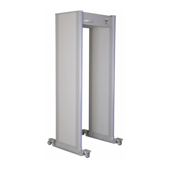
Page 52: Magnadolly Wheel Transporter
PD 6500i User MANUAL MAGNADOLLY WHeeL TrANsPOrTer The MagnaDolly transporter system may be obtained in two versions. A permanent version is preferred when frequent relocation of the unit is required. A removable version is used when moves are infrequent or when there is a requirement to move multiple units. The removable version requires no modifications to the panels for installation. -
Page 53: Adhesive Floor Mounts
ADHesIve FLOOr MOUNTs PN 1604100 Adhesive floor mounts may be used to fix the location of the PD 6500i to eliminate unauthorized relocation and to protect from tipping. The mounts are intended for smooth floors and eliminate damaging finished floors caused by anchor bolts. -
Page 54: Cma Interface Module
PD 6500i User MANUAL CMA MODULe PN 1168310 The CMA Interface Module is used in conjunction with a 10baseT network and a personal computer. It allows control, real-time monitoring and diagnostics from a remote location. The internal memory records all changes to settings and patron traffic and alarm history. - Page 56 © 2008 Garrett Metal Detectors PN 1532010 REV F...
Need help?
Do you have a question about the PD 6500i and is the answer not in the manual?
Questions and answers
We have an RX saturated alarm on a Garrett PD6500. What does this mean, and how can I rectify?