Sign In
Upload
Download
Table of Contents
Contents
Add to my manuals
Delete from my manuals
Share
URL of this page:
HTML Link:
Bookmark this page
Add
Manual will be automatically added to "My Manuals"
Print this page
×
Bookmark added
×
Added to my manuals
Manuals
Brands
Cardinal Manuals
Scales
2240
Operation manual
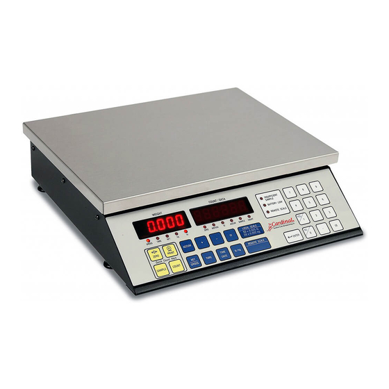
Cardinal 2240 Operation Manual
Digital counting scale
Hide thumbs
1
Table Of Contents
2
3
4
5
6
7
8
9
10
11
12
13
14
15
16
17
18
19
20
21
22
23
24
25
26
27
28
29
30
31
32
33
34
35
36
37
38
39
40
page
of
40
Go
/
40
Contents
Table of Contents
Bookmarks
Table of Contents
Table of Contents
Introduction
Specifications
Installation
Components and Controls
Precautions
Interconnections
Key Functions
Reset Function
Annunciators
Operation Without ID
Standard Sampling and Counting
Counting with an Insufficient Sample
Adjusting the Sample Quantity
Counting out of a Container
Accumulator
Weight Display
Push Button Tare
Tare Weight Entry
Metric Conversion
Operation Using ID(S)
Adding and Deleting ID Numbers
Selecting the ID Number
Verifying Active (Current) ID Number
Turning off the Active ID Number
Operation with Stored Tare Weigh
Standard Sampling and Counting
Counting with an Insufficient Sample
Adjusting the Sample Quantity
Counting out from a Container
Accumulators
Calibration and Setup
Operational Setup
Calibration Seal Installation
Sampling and Count Accuracy
Error and Status Displays
Before You Call Service
Care and Cleaning
Optional Battery Pack Operation
Thermal Label Formats
Parts Identification
Advertisement
Quick Links
1
Specifications
2
Standard Sampling and Counting
3
Calibration and Setup
4
Error and Status Displays
Download this manual
Digital Counting Scale
Models 2240 and 2241
Operation Manual
8526-M231-O1 Rev C
PO BOX 151 WEBB CITY, MO 64870
Printed in USA
10/99
PH 417-673-4631
FAX 417-673-5001
Table of
Contents
Previous
Page
Next
Page
1
2
3
4
5
Advertisement
Table of Contents
Need help?
Do you have a question about the 2240 and is the answer not in the manual?
Ask a question
Questions and answers
Related Manuals for Cardinal 2240
Scales Cardinal 225 Installation And Technical Manual
Weight indicator (116 pages)
Scales Cardinal Detecto 253 Owner's Manual
Baby scale (8 pages)
Scales Cardinal 2241 Operation Manual
Digital counting scale (40 pages)
Scales Cardinal 2341 Owner's Manual
Baby scale (8 pages)
Scales Cardinal Detecto 2341 Owner's Manual
Baby scale (8 pages)
Scales Cardinal 243 Owner's Manual
Baby scale (8 pages)
Scales Cardinal 2-OU Series Installation Manual
Checkweigher light bar (8 pages)
Scales Cardinal 225-DS Installation Manual
Dual scale input card (20 pages)
Scales Cardinal Detecto 439S Operation Instructions Manual
Stainless steel physician's scale eye-level beam scale (12 pages)
Scales Cardinal D Series Operation Manual
Price computing scale (12 pages)
Scales Cardinal CS Series Operation Manual
Cs series digital counting scale (36 pages)
Scales Cardinal Detecto Owner's Manual
6027 series/6029 series electronic physician waist-high scale (12 pages)
Scales Cardinal Detecto IB-400 Owner's Manual
Weighmobile (12 pages)
Scales Cardinal Detecto SlimPRO Operation Manual
Low profile health scale (13 pages)
Scales Cardinal HSDC series Operation Manual
Digital hanging scale battery operated (16 pages)
Scales Cardinal Detecto DR550 Owner's Manual
Digital scale (8 pages)
This manual is also suitable for:
2241
Table of Contents
Print
Rename the bookmark
Delete bookmark?
Delete from my manuals?
Login
Sign In
OR
Sign in with Facebook
Sign in with Google
Upload manual
Upload from disk
Upload from URL


Need help?
Do you have a question about the 2240 and is the answer not in the manual?
Questions and answers