Table of Contents
Advertisement
Quick Links
Download this manual
See also:
Instruction Manual
VICTOR COMPANY OF JAPAN, LIMITED
®
is a registered trademark owned by VICTOR COMPANY OF JAPAN, LTD.
®
is a registered trademark in Japan, the U.S.A., the U.K. and many other countries.
© 2000 VICTOR COMPANY OF JAPAN, LIMITED
DV CAMCORDER
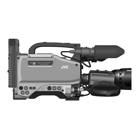
GY-DV700W
* The illustration shows the GY-DV700W DV Camcorder with the optional lens viewfinder attached.
Thank you for purchasing this JVC product. Before operating
this unit, please read the instructions carefully to ensure the
best possible performance.
Printed in Japan
SC96969:(WEK)
SC96989:(WE)
INTRODUCTION
CONTROLS,
INDICATORS AND
CONNECTORS
BASIC SYSTEM
CONNECTIONS AND
ADJUSTMENTS
POWER SUPPLY
PREPARATIONS
SETTING AND
ADJUSTMENTS
BEFORE SHOOTING
SHOOTING
OPERATION
INSTRUCTIONS
PLAYBACK MODE
TIME CODE
OPERATION
S.S.F. (Super Scene
Finder) FUNCTION
yyy
USING EXTERNAL
COMPONENTS
yyy
SETUP MENU
FEATURES OF THE
CAMERA SECTION
OTHERS
This instruction manual is made from 100% recycled paper.
SC96969:(WEK)
SC96989:(WE)
Advertisement
Table of Contents

Related Manuals for JVC GY-DV700W


Summary of Contents for JVC GY-DV700W
- Page 1 FEATURES OF THE CAMERA SECTION OTHERS * The illustration shows the GY-DV700W DV Camcorder with the optional lens viewfinder attached. Thank you for purchasing this JVC product. Before operating this unit, please read the instructions carefully to ensure the best possible performance.
-
Page 2: Main Features
Thank you for purchasing the JVC GY-DV700W DV Camcorder. These instructions are for the GY-DV700WE/WEK. Before you begin the operation of this unit, please read the instructions carefully to be sure you get the best possible performance. ● This unit records and plays back in the SP mode. -
Page 3: Table Of Contents
CONTENTS 10-6 Outputting S.S.F. Data ..........63 INTRODUCTION BASIC OPERATIONS 11. USING EXTERNAL COMPONENTS 11-1 Connecting a Video Component with DV Connector 64 MAIN FEATURES ............... 3 11-2 Connecting a PC ............65 1. INTRODUCTION 5. PREPARATIONS 1-1 Main Unit Configuration ..........6 5-1 Turning the Power ON .......... -
Page 4: Introduction
Therefore, after mounting, make sure that these parts are engaged properly. Periodical Maintenance ● When moving the GY-DV700W mounted on a tripod, any impact or vibration should be avoided as this may cause the unit to Head Cleaning become detached and to drop from the tripod. -
Page 5: Precautions For Use Of Head Cleaning Tape
Monitor screen 1-6 Battery Pack to be Used Moire or Aliasing The GY-DV700W can use any of the following battery packs. * An Anton-Bauer battery pack cannot be connected direct- Shooting stripes or fine patterns may cause a jagged effect or ●... -
Page 6: Controls, Indicators And Connectors
2. CONTROLS, INDICATORS AND CONNECTORS 2. CONTROLS, INDICATORS AND CONNECTORS 2-1 Front Section 2-1 Front Section (Cont’d) [LENS] Lens control connector CAUTION: Connect 12-pin lens control cable from lens. • As the automatic shutter is activated here, flicker may appear on the screen depending on the lighting Pin No. -
Page 7: Right Side Section
• LOLUX gain gives extremely low light level sensitivity for Used to select the status of the GY-DV700W when the • When this switch set to ON while a videocassette is warning or other abnormal condition occurring with the GY- special applications. - Page 8 CAUTION: front side section is input. • For details of the presetting of time code or user's date. The GY-DV700W delivered without the battery Make sure to move switches all the way. Do not leave a REAR : The sound from the CH-2 AUDIO IN connector bit, see page 56.
- Page 9 The display mode can be selected recording to indicate that normal recording is not being with the 4 COUNTER switch. accomplished. • Displays the VCR setup menu data when the GY-DV700W [OPERATE/WARNING] indicator Audio level meters [RF] indicator is in the VCR setup menu mode by pressing the MENU Lights when the video head is clogged.
-
Page 10: Left Side Section
Sliding this switch opens the cassette cover. • Pressing the button in stop or fast forward mode initiates • If the cassette cover is not closed, the GY-DV700W will camera image is synchronized with an external component. remain inoperative. -
Page 11: Rear Section
Back tally lamp DV CAMCORDER If the unit still does not work normally, please consult the This lamp lights up when the GY-DV700W enters the record GY-DV700 person in charge of professional video equipment at your mode. It blinks during the transition to the record mode. -
Page 12: Counter Display Contents
2. CONTROLS, INDICATORS AND CONNECTORS 2. CONTROLS, INDICATORS AND CONNECTORS 2-6 Counter Display Contents 2-7 Lens (optional) A19 × 8.7BW The counter display shows the following 4 types of information. To adjust the focus of the macro image, rotate this ring in the OPERATE/WARNING direction of arrow until the object is focused. -
Page 13: Inch Viewfinder (Optional)
This stopper screw prevents the viewfinder from coming off Steady green : During recording. Lamp Lamp the camera. Blinks green : • While the GY-DV700W switches from record-pause to recording. Viewfinder shoe • Immediately before the tape is running out Attaches to the Viewfinder Mount base on camera. - Page 14 2. CONTROLS, INDICATORS AND CONNECTORS 2. CONTROLS, INDICATORS AND CONNECTORS 2-9 Indications in Viewfinder (Cont'd) 2-9 Indications in Viewfinder (Cont'd) ● Status 1 ACCU - FOCUS ACCU - FOCUS SCENE F I L E In addition to the information on the Status 0 screen, this screen displays audio indicators and information on remaining tape, WH I TE BA L voltage and lens F-number.
- Page 15 2. CONTROLS, INDICATORS AND CONNECTORS 2. CONTROLS, INDICATORS AND CONNECTORS 2-9 Indications in Viewfinder (Cont'd) 2-9 Indication in Viewfinder (Cont'd) Alarm Message Display Safety Zone Three types of safety zone items can be displayed in the viewfinder. Select the required one with the SAFETY ZONE item on the ACCU - FOCUS VF DISPLAY menu screen.
-
Page 16: Basic System Connections And Adjustments
1 When used in the 4:3 mode, approximately 20% of the image angle is shifted to the telephoto-side. Connect the cable 2 To use the 16:9 mode, change the setting by means of the ASPECT RATIO item in the GY-DV700W’s camera OPERATION connector as shown in Sliding MENU. -
Page 17: Attaching The Microphone (Provided)
3. BASIC SYSTEM CONNECTIONS AND ADJUSTMENTS 3. BASIC SYSTEM CONNECTIONS AND ADJUSTMENTS 3-4 Attaching the Microphone (provided) 3-6 Attaching the Tripod Base (provided) Provided Microphone Connecting the provided microphone to the viewfinder. Use the provided tripod base to place the camera on a tripod. The provided microphone is a phantom microphone. -
Page 18: Inserting And Replacing Backup Lithium Batteries
DC power is applied. Then switch ON again. ● If the GY-DV700W is left with the battery pack attached, a small amount of power is consumed even if the POWER switch on the GY-DV700W is set to OFF. Remove the battery pack when the GY-DV700W is not going to be used. -
Page 19: Attaching A Flat Shape Type Battery Pack
To use an Anton-Bauer battery pack (Propack 13/14, Trimpack 13/14, Magnum 13/14, Compack 13/14 Series), it is necessary to detach the battery case from the GY-DV700W and replace it with the Anton-Bauer battery holder. Use the following battery holder. Insert the battery pack into the battery case with its electrodes •... -
Page 20: Preparations
Select the GY-DV700W operation mode with the VTR switch. After the remaining battery power warnings appear, the • The GY-DV700W operation mode may differ when the power is turned ON and when the cassette is loaded depending on the GY-DV700W automatically stops operation if the battery setting of the VTR switch as follows: power operation is continued. -
Page 21: Cassette Loading And Unloading
Lithium battery compartment ADVANCE button • A cassette cannot be loaded or unloaded while the GY-DV700W is in POWER OFF mode. • Use a videocassette tape marked MiniDV. • The videocassette should be held vertical and inserted straight into the slot. -
Page 22: Setting And Adjustments Before Shooting
Outdoors Connect a colour video monitor to the MONITOR OUT 4 5600K+1/64ND Outdoors under clear sky connector of the GY-DV700W. Using the SHUTTER dial, set the shutter speed to OFF. DV CAMCORDER GY-DV700W Set the OUTPUT switch to BARS to output the colour bar signal (EBU type colour bars). -
Page 23: Back Focus Adjustment
6. SETTING AND ADJUSTMENTS BEFORE SHOOTING 6. SETTING AND ADJUSTMENTS BEFORE SHOOTING 6-4 Back Focus Adjustment 6-5 White Balance Adjustment It is only necessary to perform this when the lens is attached Since the colour of light (colour temperature) varies depending on the light source, it is necessary to re-adjust the white balance for the first time or when focusing is not correct in both the when the main light source illuminating the subject changes. -
Page 24: Switch Settings Of The Vcr Section
Audio input signal selection AUTO MANUAL AUDIO SELECT Use the AUDIO INPUT switch to select whether the sound Select the time (in minutes) until the GY-DV700W enters the AUDIO INPUT CH-1 CH-2 CH-1 AUDIO CH-2 FRONT recorded on audio channel 1 or 2 is the sound from the... -
Page 25: Recording Level Adjustment
6. SETTING AND ADJUSTMENTS BEFORE SHOOTING 6. SETTING AND ADJUSTMENTS BEFORE SHOOTING 6-10 Monitoring Audio during Recording 6-9 Recording Level Adjustment CH-1 Audio CH-2 Audio select switch select switch OPERATE/WARNING LIGHT RESET AUTO MONITOR MANUAL FILTER SELECT COUNTER 1 3200k ALARM AUDIO SELECT 2 5600k+1/8ND... -
Page 26: Shooting Operation
See "White Balance Adjustment" on page 45. pressed, the viewfinder REC indicator lamp may blink and the GY-DV700W may not enter the record mode. To remedy this condition set the POWER switch to OFF and wait for 5 seconds or more before turning the power on again. -
Page 27: Vcr Save Mode
The OPERATE indicator lights orange. The display mode resumes. backlight turns off. * This function does not work when the GY-DV700W is in When the RET button is kept pressed, the tape is rewound the save mode or stop mode. -
Page 28: Playback Mode
8. PLAYBACK MODE 8. PLAYBACK MODE 8-1 Playback Procedure 8-2 Fast-Forward, Rewind REW button FF button EJECT switch OPERATE/WARNING LIGHT RESET MONITOR FILTER SELECT COUNTER 1 3200k ALARM 2 5600k+1/8ND STOP PLAY STILL 3 5600k EJECT 4 5600k+1/64ND SHUTTER STATUS MONITOR OPERATE/WARNING MENU... -
Page 29: Time Code Operation
9. TIME CODE OPERATION 9. TIME CODE OPERATION The GY-DV700W records EBU-standard time codes and user's bits. In the play or record mode, the reproduced time codes or TIME CODE PRESETTING PROCEDURE user's bits are shown on the counter display. -
Page 30: Recording Time Codes By Slave-Locking The Built-In Time Code Generator With External Tcg
Note : The GY-DV700W incorporates a time code reader. During playback, the time code or user's bit data recorded on the tape is The SLAVE indicator lights on the display. When the power is switched ON while external sync signal displayed on the counter display. -
Page 31: Super Scene Finder) Function
• When recording in the S.S.F. mode, the reel number (cassette number) for each cassette is recorded in the memory of the of the OUT point and the “∗” mark is not shown in the GY-DV700W and on tape. viewfinder. -
Page 32: Deleting S.s.f. Data
For how to make connections for this, refer to “Connecting to a cassette tape has not been taken out, the S.S.F. data stored PC” on page 65. in the memory of the GY-DV700W are output when the RS- RESET button 232C command D5h is received. -
Page 33: Using External Components
See page 68. SELECT to "RS232C". See page 68. • To remote control the GY-DV700W’s VCR using the DV connector’s IEEE1394 option, set the VCR Setup Menu item No. 050 REMOTE SELECT to “IEEE1394”. See page 68. -
Page 34: Setup Menu
For servicing → See the service manual page 1-18, 12. SETUP MENU “1.13 SERVICE MENU (VCR)”. 12. SETUP MENU 12-1 VCR Setup Menu 12-1 VCR Setup Menu (Cont'd) The setup menus for the VCR section can be set while observing the menu in the viewfinder and on the unit's counter display. DISPLAYING AND SETTING VCR SETUP MENUS The set contents are stored in the memory and retained even after the power is switched OFF. -
Page 35: Vcr Setup Menu Contents
• When the VCR Setup Menu item No. 398 S.S.F. MODE changed in the stop mode or when a The GY-DV700W records two of these tracks. The GY- is set to CUE or MARK, the time code generator’s cassette is not loaded. -
Page 36: Camera Menu Screen Flow
12. SETUP MENU 12. SETUP MENU 12-2 Camera Menu Screen Flow 12-3 How to Select from the Camera Menu Camera Menu Screen Flow Press the STATUS button for 1 second to display the CAMERA MENU screen in the viewfinder. As illustrated below, the Camera Menu is a menu screen comprising several layers. The first layer of the CAMERA MENU screen is for choosing and setting the menus required in accordance with functions or purposes. -
Page 37: Vf Display Screen
12. SETUP MENU 12. SETUP MENU 12-4 VF Display Screen 12-5 OPERATION Screen Item Function, Operation Variation Range Initial Setting Item Function, Operation Variation Range Initial Setting F NO. Selects whether or not the F-number of the lens iris is displayed on the ON (WEK) ASPECT RATIO Sets the image size of the video signal. -
Page 38: Process Screen
For servicing See the service manual page 1-16, “1.12 CHANGING → THE COLOR MATRIX SETTING”. 12. SETUP MENU 12. SETUP MENU 12-6 PROCESS Screen 12-7 ADVANCED PROCESS Screen Item Function, Operation Variation Range Initial Setting Item Function, Operation Variation Range Initial Setting COLOR Sets the colour matrix MASTER... -
Page 39: File Manage Screen
12. SETUP MENU 12. SETUP MENU 12-9 FILE MANAGE Screen 12-10 SETUP Screen The unit has three files that can be used for storing camera menus. The FILE MANAGE screen is for performing the operations for Item Function, Operation Variation Range Initial Setting saving the set CAMERA MENU. -
Page 40: Resetting Of Camera Menu Setting Values
13. FEATURES OF THE CAMERA SECTION 12. SETUP MENU 12-11 Resetting of Camera Menu Setting Values 13-1 Full-Time Auto White Balance (FAW) Using the FILE MANAGE screen, the CAMERA MENU settings can be reset to the initial setting values. On the FILE MANAGE The FAW function adjusts the white balance - - - OPERAT I ON - - - screen, select the file of the CAMERA MENU to be reset, and then perform the resetting operation. -
Page 41: Iris (Brightness) Adjustment
13. FEATURES OF THE CAMERA SECTION 13. FEATURES OF THE CAMERA SECTION 13-2 IRIS (Brightness) Adjustment 13-3 Shooting the Screen Image on a Computer Monitor ADJUSTMENT OF LENS IRIS Outline The lens iris can be adjusted using any of the The following operation allows the alignment of the shutter following three methods. -
Page 42: Gain (Sensitivity) Adjustment
13. FEATURES OF THE CAMERA SECTION 13. FEATURES OF THE CAMERA SECTION 13-4 Gain (Sensitivity) Adjustment 13-5 Switch Setup According to Illumination and Subject The gain should be switched when the brightness is insufficient due to poor lighting conditions. Various switch settings are performed to accommodate the conditions of the illumination and the subject when shooting. GAIN SWITCHING SWITCH FUNCTIONS 1AUTO IRIS LEVEL switch... -
Page 43: How To Use Skin Detail
13. FEATURES OF THE CAMERA SECTION 13. FEATURES OF THE CAMERA SECTION 13-6 How to Use Skin Detail 13-6 How to Use Skin Detail (Cont’d) The contour emphasis in the skin colour areas of the video signal can be controlled and made to appear gentle and smooth. Confirming the colour tone area adjusted Setting the Color and Range of the Skin Detail with the Skin Detail function... -
Page 44: Others
LOW BATTERY In other cases, please consult the person in charge of professional video equipment at your nearest JVC-authorized service agent. Lights in case of video head clogging. Operation : Continues. (Counter display) (Head clogging is detected and indicated during Remedy : Clean the head with the special head “HEAd CLoG”... -
Page 45: Warnings In Viewfinder
WARNINGS IN VIEWFINDER In the case of troubles occurring during operation of the GY-DV700W, it performs a self-test to identify the cause and displays the result in the form of an error code. The error code consists of the "main code" which indicates its contents and the "sub-code" which indicates the details. -
Page 46: Troubles With Error Code Outputs
4200 Cassette housing abnormality. Operation stops. All operations The GY-DV700W remains inoperative as long as the cassette door is open. are rejected. Recording is not possible. • Is switch on cassette set to REC? If it is set to SAVE, set it to REC. -
Page 47: Hour Meter Display
(WEK) 14. OTHERS 14. OTHERS 14-2 Hour Meter Display 14-3 How to Attach the Wireless Receiver (Sony WRR-810) The unit can display the accumulated running time of the head drum as hour meter data on the counter display. The hour meter can A cover with a rectangular hole for mounting the wireless receiver is attached to the camera when shipped from the factory. -
Page 48: Specifications
14. OTHERS 14. OTHERS 14-4 Specifications 14-4 Specifications CAMERA SECTION INPUT/OUTPUT SIGNALS OPTIONAL ACCESSORIES : 1 V (p-p), 75 Ω (BNC) unbalanced Image pickup devices : 2/3-inch 16:9 interline CCD x 3 Video signal output Colour separation optical system: composite output. Viewfinder : VF-P116W : Y 1 V (p-p) 75 Ω...
Need help?
Do you have a question about the GY-DV700W and is the answer not in the manual?
Questions and answers