Table of Contents
Advertisement
Quick Links
QUICK START
Read this section if you want to install and operate the RPE 228 without wading through the detailed descriptions in this
manual. If the control software has not yet been installed on your computer, refer to SOFTWARE OPERATION on page
Manual-5 first.
Turn the amplifier(s) down or off until all connections are complete. Connect balanced audio INPUTS and OUTPUTS
to the handy Euroblock connectors on the rear. Connect the RW 232 INPUT jack on the rear to a serial (COM) port on a
PC-compatible computer using a standard 9-pin RS-232 cable (a short one is supplied with the unit, which is intended to
connect between units in a rack). The cable or adaptor must not be a null-modem type.
Locate the RW 232 DEVICE ADDRESS switch on the rear panel. If this unit is to be tested by itself, set it to '1' by
setting all switches off (down), except switch one (labeled '1' on the chassis, the right-most switch). If there is more than
one unit, refer to SETTING THE DEVICE ADDRESS to set a unique number.
Apply power by connecting the RS 1 remote power supply to the red telephone-style jack on the rear of the unit.
CAUTION: don't connect anything but an approved RANE power supply to this jack. If the RS 1 and the RPE 228 are
getting power, the front panel yellow POWER light will be on.
Start your computer, run Windows
Setup window may appear. If it doesn't, select System Setup from the Setup menu. Be careful to select the COM port
which is physically connected to the RPE 228. Click OK. Now, the Device Selection window may appear. If it doesn't,
choose Select from the Device menu. Click on Poll, ... and the Devices Found will display the number of units found.
Click the Stop button. Select the unit listed in the Device Selection window and click OK. If no unit was found, please
refer to the TROUBLESHOOTING section.
Several clues indicate communication between the computer and the RPE 228. The yellow COM (communications)
lights on the unit should flash periodically. The Memory numbers (1-16) near the top of the computer screen should be
black rather than grey. Clicking the BYPASS button on the screen causes one Channel of the unit to enter bypass.
WEAR PARTS: This product contains no wear parts.
Windows is a registered trademark of Microsoft Corporation.
RaneWare is a registered trademark of Rane Corporation
OPERATORS MANUAL
®
, and launch our software by double-clicking on the RaneWare
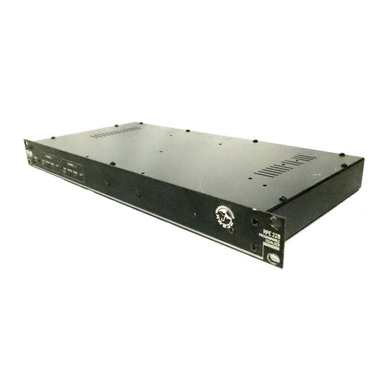
REMOTE PROGRAMMABLE EQUALIZER
RPE 228
®
icon. The System
Manual-1
Advertisement
Table of Contents

Subscribe to Our Youtube Channel
Related Manuals for Rane RPE 228


Summary of Contents for Rane RPE 228
-
Page 1: Quick Start
Apply power by connecting the RS 1 remote power supply to the red telephone-style jack on the rear of the unit. CAUTION: don’t connect anything but an approved RANE power supply to this jack. If the RS 1 and the RPE 228 are getting power, the front panel yellow POWER light will be on. -
Page 2: Front Panel Description
The chassis ground is intended to be connected to an earth are marked on the rear panel. To set a specific address, refer ground. The RPE 228 is intended to be connected to other to the “Setting the Device Address” section. -
Page 3: Rear Panel Description
AC outlet cover by means of a wire connected to a screw on the chassis with a star washer to guarantee proper contact. See TROUBLESHOOTING, back page. Remote POWER jack is for connection to a Rane RS 1 or compatible power supply. CANADIAN EMC NOTICE... -
Page 4: Setting The Device Address
‘1’ and ‘2’ yields address ‘3’. In the following table, 0 means switch down (OFF), 1 means switch up (ON), and the left-most digit corresponds to the switch labeled ‘128’. Rane provides a special calculator to assist in setting the dip switches on the back of each unit. Alt-Tab to the Windows Program Manager, and in the RaneWare program group, launch the RaneWare Address Calculator. -
Page 5: Software Operation
A RaneWare program group is now created, containing RPE 228 communications input port. No interface boxes are RaneWare, the RaneWare Address Calculator, and RaneWare required; just a cable and your computer. - Page 6 228. While Local Edit is selected, clicking on any of the mouse button Memory buttons displays the preview curve without sending The menus also provide: it to the RPE 228. • Extensive On-Line Help The Device button brings up a selection menu of up to 15 • Device Selection RaneWare units connected to the computer.
- Page 7 Device > Name Device System > Edit Installation Info Devices and channels can also be given custom names, This selection allows you to enter the Project name, tailored to your installation. installation Site and System Engineer for a given project. All If your installation changes by adding more RaneWare of these are printed on the Device Report printouts.
-
Page 8: Troubleshooting
For more information on balanced interconnection and grounding, please refer to RaneNote 110, “Sound System Interconnection”(next section). ©Rane Corporation 10802 47th Ave. W., Mukilteo WA 98275-5098 TEL (425)355-6000 FAX (425)347-7757 WEB http://www.rane.com Manual-8 All features & specifications subject to change without notice.
Need help?
Do you have a question about the RPE 228 and is the answer not in the manual?
Questions and answers