Advertisement
Quick Links
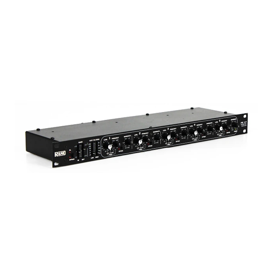
OPERATORS MANUAL
GAIN
CUT FILTERS
+12
–12
250
3k
180
OL
5k
80
0
0
10k
35
30k
20
–12
+12
10
40k
BYPASS
IN
OUT
LOW
HIGH
QUICK START
Those who choose not to read this modest informational snippet (intended to ward off one of life's embarrassing
moments) are those who wish to hasten the point at which their entire sound system locks up, screams unmercifully,
shatters windows, causes dogs to howl, babies to cry, and melts all the compression drives, dripping molten titanium all
over the hand-polished walnut decor. Pity.
There are only a few things to check when using a PE 17. Always set both GAIN controls as close to the top of the
panel as possible without causing the OL LED to light constantly. Use the CUT FILTERS to tailor the bandwidth for each
application. Always check that each FREQ x multiplier switch (located beneath each FREQ control) is set to the correct
position. Great surprises result from false settings.
For extra-deep notching applications, use Bands 3 and 4 and set them exactly the same. Notches as deep as 30 dB are
possible, since Bands 3 and 4 are in series while most other bands are in parallel (see the Block Diagram in the Data Sheet).
Hook-up is simple. The PE 17 accepts all combinations of balanced or unbalanced, XLR or ¼" connectors. However,
the INPUT connectors are wired in parallel and may not be used together. Use only one at a time. They will not function as
a summing type of input for two different sources, but they may be used in a daisy chain fashion to feed other units. On the
other hand (to randomly pick a hackneyed expression), you may use the paralleled Outputs to drive two destinations.
Never connect anything except a Rane approved AC power supply to the thing that looks like a red telephone jack on
the rear of the PE 17.
WEAR PARTS: This product contains no wear parts.
1
2
LEVEL
FREQUENCY
BANDWIDTH
LEVEL
FREQUENCY
-3
235
460
0.6
1.0
-3
235
3
3
-6
6
150
1k
0.3
1.8
-6
6
150
-12
9
-12
9
-15
12
100
2k
.03
2.0
-15
12
100
dB
Hz
OCTAVE
dB
x10
x1
x0.1
BYPASS
x10
x1
x0.1
FREQ
FREQ
3
BANDWIDTH
LEVEL
FREQUENCY
BANDWIDTH
460
0.6
1.0
-3
235
460
0.6
3
1k
0.3
1.8
-6
6
150
1k
0.3
-12
9
2k
.03
2.0
-15
12
100
2k
.03
Hz
OCTAVE
dB
Hz
OCTAVE
BYPASS
x10
x1
x0.1
BYPASS
FREQ
PARAMETRIC EQUALIZER
4
5
LEVEL
FREQUENCY
BANDWIDTH
LEVEL
1.0
-3
235
460
0.6
1.0
-3
3
3
1.8
-6
6
150
1k
0.3
1.8
-6
6
-12
9
9
2.0
-15
12
100
2k
.03
2.0
-15
12
dB
Hz
OCTAVE
dB
x10
x1
x0.1
BYPASS
x10
FREQ
FREQ
PE 1 7
FREQUENCY
BANDWIDTH
235
460
0.6
1.0
PE 17
150
1k
0.3
1.8
PARAMETRIC
EQUALIZER
100
2k
.03
2.0
Hz
OCT.
x1
x0.1
BYPASS
POWER
Manual-1
Advertisement

Subscribe to Our Youtube Channel
Related Manuals for Rane PE 17


Summary of Contents for Rane PE 17
-
Page 1: Parametric Equalizer
Pity. There are only a few things to check when using a PE 17. Always set both GAIN controls as close to the top of the panel as possible without causing the OL LED to light constantly. Use the CUT FILTERS to tailor the bandwidth for each application. -
Page 2: Front Panel Description
Overall BYPASS switch & indicator: Engaging this pushbutton energizes the Bypass relay. This provides a complete hard-wire Bypass of the PE 17 with no active electronics in the signal path. A red LED indicates the unit is in the BYPASS mode. -
Page 3: Rear Panel Description
Units with outboard power supplies, like the PE 17, do NOT ground the chassis through the line cord. Make sure this unit is grounded either to another chassis which is earth grounded (like the power amplifier), or directly to the grounding screw on an AC outlet cover by means of a wire connected to the chassis ground point found on the rear to guarantee proper contact. -
Page 4: Operating Instructions
Rane makes some other great parametrics such as found in the RPM series that may solve some of your other system issues. ©Rane Corporation 10802 47th Ave. W., Mukilteo WA 98275-5098 USA TEL (425)355-6000 FAX (425)347-7757 WEB http://www.rane.com Manual-4 103051...
Need help?
Do you have a question about the PE 17 and is the answer not in the manual?
Questions and answers