Panasonic WV-RM70 Operating Instructions Manual
Camera controller
Hide thumbs
Also See for WV-RM70:
- Operating instructions manual (36 pages) ,
- Operation instructions manual (36 pages)

Related Manuals for Panasonic WV-RM70


Summary of Contents for Panasonic WV-RM70
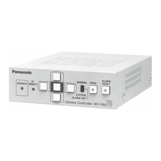
- Page 1 Camera Controller WV-RM70 Before attempting to connect or operate this product, please read these instructions completely.
- Page 2 CAUTION CAUTION: Before attempting to connect or operate this prod- RISK OF ELECTRIC SHOCK DO NOT OPEN uct, please read the label on the bottom. CAUTION: TO REDUCE THE RISK OF ELECTRIC SHOCK, DO For U.S.A NOT REMOVE COVER (OR BACK). NO USER SER- Warning: VICEABLE PARTS INSIDE.
-
Page 3: Table Of Contents
CONTENTS PREFACE ..................................2 FEATURES ..................................2 PRECAUTIONS ................................3 MAJOR OPERATING CONTROLS AND THEIR FUNCTIONS ..................4 CONNECTIONS ................................7 OPERATING PROCEDURE ............................13 SPECIFICATIONS ................................. 32... -
Page 4: Preface
PREFACE FEATURES The WV-RM70 Camera Controller, when combined with The WV-RM70 Camera Controller enables remote con- the optional WV-CP610 and WV-BP510 series CCTV trol of the following functions: Camera, enables remote control of camera settings. • Remote control of camera settings for the WV-... -
Page 5: Precautions
PRECAUTIONS • Do not use strong or abrasive detergents when • Do not attempt to disassemble the unit. cleaning the unit body. In order to prevent electric shock, do not remove Do use a dry cloth to clean the unit when dirty. screws or covers. -
Page 6: Major Operating Controls And Their Functions
MAJOR OPERATING CONTROLS AND THEIR FUNCTIONS e r t y u !1 !2 ALARM TERM VIDEO CAMERA DC12V IN NORMAL PROG RESET RESET OUT DATA OPERATE REMOTE ALARM OUT T(A) T(B) R(A) R(B) SYSTEM ALARM OFF Camera Controller WV-RM... - Page 7 1. Power Indicator (OPERATE) 7. Right Switch (B) This indicator lights up when DC power is supplied This switch is used to move the cursor (in the Setup to the DC 12V Input Terminal. Menu) in the right direction or move the Pan/Tilt Head toward the right direction.
- Page 8 ALARM OUT: The alarm output signal is provided 14. Video Output Connector (VIDEO OUT) at this terminal for the Time Lapse VCR. A 1.0 Vp-p / 75 composite video signal is provid- ed at this connector. 12. Data Terminal These terminals are used to transmit / receive 15.
-
Page 9: Connections
CONNECTIONS Pulse (VTR): +5V DC approx. 500msec. Initially, VTR position is selected at the factory. 1. Dip Switch Setting 2. Set switch (SW2) on the board to choose the char- Before connecting this controller, confirm the Dip acter display mode on the monitor. Switch Setting if the system setting change is required. - Page 10 5. Set switch (SW5) on the board to choose the data (1) In case the buzzer is operable within the capacity line selection mode for data terminal. of Alarm Output Terminal, connect buzzer as 4 LINE : normal connections are shown right.
-
Page 11: System Connections
3. System Connections Basic Connection Pan/Tilt Camera WV-CS304 Camera WV-CP610 Receiver Camera Controller WV-RM70 RS-485 Time Lapse VCR Converter (RS-485/ RS-232C) Motion Detect Output Personal Computer Monitor... - Page 12 System 100 System 300 WV-CP610 WV-CP610 WV-CS304 WV-BS204 WV-RM70 WJ-SW208 WJ-MP404 RS-485 ALARM OUT WJ-SQ508 Converter (RS-485/ Converter WV-RM70 RS-232C) (RS-485/ RS-232C) Time Lapse WV-CU300 WV-CU101 Monitor Monitor Time Lapse VCR -10-...
- Page 13 WV-RM70 WJ-MP404 A ft A ft B ft Position of the Position of the Position of the switch of WV-RM70 switch of WV-RM70 switch of WJ-MP404 A < 1300 A + B < 1300 1300 A < 2300 1300 A + B < 2300 2300 A <...
- Page 14 4. Connection with the Personal Personal Computer Camera Controller Computer T(A) R(A) T(B) R(B) 4 Data Line (Dip Switch SW5 : 4 LINE) R(A) T(A) R(B) T(B) Personal Computer Camera Controller T(A) R(A) T(B) R(B) R(A) T(A) R(A) R(B) T(B) R(B) T(A) T(B)
-
Page 15: Operating Procedure
OPERATING PROCEDURE Before starting the following procedures, all system components should be turned on. 1. Mode Selection This controller can select the activated mode by selecting Mode Selection Switch located on the front panel. Switch Position Activated Mode Functions Function 1 : Controller setup Function 2 : Camera Setup (for WV-CP610 series) Function 3 : Camera Control NORMAL... - Page 16 2. Entering Program Menu Program Menu By pressing the Program (PROG) Switch for more Camera Control Iris Control than 2 seconds, when Mode Selection Switch is Sens Up Control selected at Normal (NORMAL) position or Alarm Shutter Off (ALARM OFF) position, the following displays appear on the monitor screen.
-
Page 17: Camera Control
3. Camera Control 3-1. Lens Iris Control The following function is available only when speci- Move the cursor to the “Camera Control” position fied lens is mounted on the specified camera. by pressing the Up (D) Switch or the Down (C) Switch, then press the Set Switch to display the fol- 1. - Page 18 3-2. Electronic Sensitivity Up 3-3. Electronic Shutter The following function is available only when speci- The following function is available only when speci- fied camera with the electronic sensitivity feature is fied camera with the electronic shutter feature is used. used.
- Page 19 3-4. Back Light Compensation (BLC) The following function is available only when speci- fied camera with the Auto/Preset BLC Function is used. AGC :On 1. Display the BLC Menu as shown in Fig. 7 by repeating the previous procedures. Fig. 8 2.
- Page 20 Press the Set Switch repeatedly to select the 2. Press the Right (B) Switch or the Left (A) Switch to desired functions. The function is selected as select desired mode, “ATW” or “AWC”. shown in the following sequence. After completing the above settings, press the Tilt/Pan Zoom/Focus Program (PROG) Switch to return the previous...
- Page 21 2. Press the Up (D) Switch or the Down (C) Switch to 2. Press the Up (D) Switch or the Down (C) Switch to move the Pan/Tilt Head toward up or down. Press adjust the lens zoom to achieve the desired picture the Rignt (B) Switch or the Left (A) Switch to move while observing the monitor screen.
- Page 22 4-5. Pan Action (Auto/Random Panning) 2. Press the Left (A) Switch repeatedly to turn on or 1. Display the Pan Menu as shown in Fig. 15 by off the user’s auxiliary switch 1 in the Receiver (WV- repeating the previous procedures. RC100 or WV-RC150).
- Page 23 The following functions are only available with the camera that has set up functions such as the Notes: Panasonic WV-CP610 or WV-BP510 series camera. • Refer to the Operating Instructions of the camera for more details. 1. Press the Program (PROG) Switch for more than 2 •...
- Page 24 6. Controller Set Up 3. Move the cursor to the “Disable” position by press- ing the Up (D) Switch or the Down (C) Switch, then press the Set Switch and “Enable” is dis- 6-1. Entering Controller Setup Menu played. 1. Press the Program (PROG) Switch for more than 2 seconds to display the Program Menu.
- Page 25 6-2. System Setup 5. Press the Program (PROG) Switch to return to the 1. Display the Controller Set Up Menu by repeating previous Program Menu. the previous procedures. To return to the normal camera picture, press the Program (PROG) Switch again. (1) Camera ID Setting ** Controller Set Up ** ** System **...
- Page 26 4. Move the cursor to the “Camera ID” position ABCDEFGHIJKLM by pressing the Up (D) Switch or the Down NOPQRSTUVWXYZ 0123456789 (C) Switch, then press the Set Switch to dis- ().,'":;&#!?= play the Camera ID Editing Menu as shown in +-*/%$ Fig.
- Page 27 8. When blank space is needed, move the char- ABCDEFGHIJKLM acter cursor to the “Space” position by press- NOPQRSTUVWXYZ 0123456789 ing the switches, then press the Set Switch. ().,'":;&#!?= The blank space is inserted into the cursor +-*/%$ position in the editing area. Space Posi Return Clear DOOR ..
- Page 28 The Camera ID display position can be placed (2) Cable Compensation Setting anywhere on the screen by pressing the Up 1. Display the System Menu as shown in Fig. 27 (D) Switch, Down (C) Switch, Left (A) Switch by repeating the previous procedures. and Right (B) Switch.
- Page 29 (3) Alarm Time Setting ** System ** 1. Display the System Menu as shown in Fig. 27 Camera ID Off * by repeating the previous procedures. Cable Comp Alarm Time 60 S Alarm Display Off 2. Move the cursor to the “Alarm Time” position by pressing the Up (D) Switch or the Down (C) Switch, then select the desired alarm time, Return...
- Page 30 3. Move the cursor to the desired item by pressing 2. Move the cursor to the “Unit Number” position the Up (D) Switch or the Down (C) Switch and by pressing the Up (D) Switch or the Down then select the desired mode by pressing the Right (C) Switch, then select the desired unit num- (B) Switch or the Left (A) Switch.
- Page 31 (4) Parity Check Setting Select desired mode, Not Use or Use, by 1. Display the communication Menu as shown in pressing the Right (B) Switch or the Left (A) Fig. 30 by repeating the previous procedures. Switch. 2. Move the cursor to the “Parity Check” position (7) Wait Time Setting by pressing the Up (D) Switch or the Down 1.
- Page 32 Select the alarm data transmission mode as fol- When this unit receives an alarm from the camera, lows. such as Panasonic WV-CP610 is activated at Off: The controller does not transmit alarm data to motion detect mode, or camera site receiver WV- the computer.
- Page 33 (2) To Cancel Alarm Up Switch Press the Alarm Reset (ALARM RESET) Switch for alarm reset. The indicator light turns off and “Alarm” display on the monitor screen disappears. 8. All Reset Left Switch Right Switch It is possible to undo all the changes the end user made to return to the factory settings without having to Down Switch Set Switch...
-
Page 34: Specifications
Data Input / Output : RS-485 Remote Control Functions Camera Set Up : For Panasonic WV-CP610 or WV-BP510 series camera Camera Functions : Electronic Sensitivity Up Mode Select : Auto / Manual / Off Electronic Shutter : On / Off, Shutter Speed Select... - Page 35 Ambient Operating Temperature : 14˚F - 140˚F ( 10˚C - +60˚C) Ambient Operating Humidity : Less than 90% Dimensions : 5-7/16” (W) x 7-5/16” (D) x 2”(H) 138 (W) x 185 (D) x 51 (H) mm Weight : 1.8 lbs. (0.8 kg) Weight and dimensions shown are approximate.
- Page 36 Video Imaging Systems Company A Division of Panasonic Broadcast & Television Systems Company A Unit of Matsushita Electric Corporation of America Executive Office: One Panasonic Way 4H-2, Secaucus, New Jersey 07094 Regional Offices: Northeast: One Panasonic Way, Secaucus, NJ 07094 (201) 348-7303...
Need help?
Do you have a question about the WV-RM70 and is the answer not in the manual?
Questions and answers