Table of Contents
Advertisement
Copyright
Copyright © 2011 MiTAC International Corporation. All rights reserved. No part of
this manual may be reproduced or translated without prior written consent from
MiTAC International Corporation.
Trademark
All registered and unregistered trademarks and company names contained in this
manual are property of their respective owners including, but not limited to the
following.
®
TYAN
is a trademark of MiTAC International Corporation.
®
Intel
is a trademark of Intel
AMI, AMI BIOS are trademarks of AMI Technologies.
®
Microsoft
, Windows
®
Winbond
is a trademark of Winbond Electronics Corporation.
Notice
Information contained in this document is furnished by MiTAC International
Corporation and has been reviewed for accuracy and reliability prior to printing.
MiTAC assumes no liability whatsoever, and disclaims any express or implied
warranty, relating to sale and/or use of TYAN
warranties relating to fitness for a particular purpose or merchantability. MiTAC
retains the right to make changes to product descriptions and/or specifications at
any time, without notice. In no event will MiTAC be held liable for any direct or
indirect, incidental or consequential damage, loss of use, loss of data or other
malady resulting from errors or inaccuracies of information contained in this
document.
S8005
Version 1.1
®
Corporation.
®
are trademarks of Microsoft Corporation.
®
products including liability or
Advertisement
Table of Contents

Related Manuals for TYAN S8005


Summary of Contents for TYAN S8005
- Page 1 Corporation and has been reviewed for accuracy and reliability prior to printing. MiTAC assumes no liability whatsoever, and disclaims any express or implied ® warranty, relating to sale and/or use of TYAN products including liability or warranties relating to fitness for a particular purpose or merchantability. MiTAC retains the right to make changes to product descriptions and/or specifications at any time, without notice.
-
Page 2: Table Of Contents
3.5 Boot ....................61 3.6 Security.................... 64 3.7 Chipset .................... 65 3.8 Power....................74 3.9 Exit....................75 Chapter 4: Diagnostics................77 4.1 Beep Codes..................77 4.2 Flash Utility ..................77 4.3 AMIBIOS Post Code................ 78 Glossary..................... 81 Technical Support ..................87 http://www.tyan.com... -
Page 3: Before You Begin
The retail motherboard package should contain the following: S8005 Motherboard 6 x Serial ATA Cable 1 x SAS Cable (for S8005WAGM2NR SKU only) USB2.0 Cable S8005 User’s manual S8005 Quick reference guide ® TYAN Driver CD I/O shield Retention Module... - Page 4 NOTE http://www.tyan.com...
-
Page 5: Chapter 1: Instruction
64-bit computing, high-bandwidth memory design, and lightning-fast PCI-E bus implementation. The S8005 not only empowers you in today’s demanding IT environment but also offers a smooth path for future application usage. All of this provides S8005 the power and flexibility to meet the needs of nowadays application. - Page 6 (1) 3 port rear audio jack (Line-in/Line-out/Mic) Input /Output RJ-45 (2) GbE ports (1) 3x2-pin LCD module header Power EPS12V 24-pin + 8-pin power connectors (1) 2x12-pin TYAN front panel header (TYAN- Front Panel SSI) IPMB (1) 1x4-pin header (1) IDE connector SATA...
-
Page 7: Ast2050 Application
M2061, PCI-E x8 to PCI-X 1U riser card (left) Riser Card accessories for M2083-RS, PCI-E 1U riser card (left) future upgrade 1.3 AST2050 Application Please visit the TYAN Web Site at http://www.tyan.com to download the latest AST2050 User’s Guide. http://www.tyan.com... - Page 8 NOTE http://www.tyan.com...
-
Page 9: Chapter 2: Board Installation
(5) Inspect the board for damage. The following pages include details on how to install your motherboard into your chassis, as well as installing the processor, memory, disk drives and cables. NOTE: Do not apply power to the board if it has been damaged. http://www.tyan.com... -
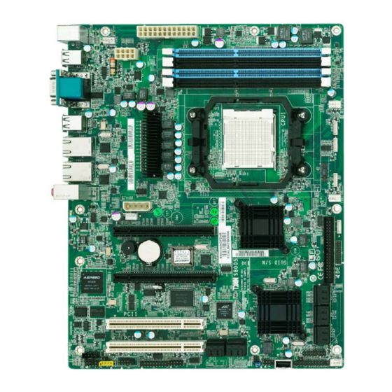
Page 10: Board Image
2.1 Board Image This picture is representative of the latest board revision available by the time of publishing. The board you receive may not look exactly like the above picture. http://www.tyan.com... -
Page 11: Block Diagram
2.2 Block Diagram S8005 Block Diagram http://www.tyan.com... -
Page 12: Board Parts, Jumpers And Connectors
This diagram is representative of the latest board revision available at the time of publishing. The board you receive may not look exactly like the above diagram. For the latest board revision, please visit our web site at www.tyan.com. http://www.tyan.com... - Page 13 JP13 Chassis Intrusion Header JP15 Onboard VGA Jumper IPMB Connector Audio Front Panel Header CD-IN Header COM2 Connector TYAN-SSI Front Panel Header LCM Module Header (Barebones use only) 8-pin FAN Headers (barebones use J44/J45/J46/J47 only) CPUFAN/FAN1/FAN2/FAN3 4-pin FAN Headers 24-pin EPS 12V Main Power Connector...
- Page 14 JP12 JP13 http://www.tyan.com...
- Page 15 The Chassis Intrusion Header provides chassis intrusion- monitoring function. Note: For use with chassis that support this feature. Signal Intruder# JP12: WDT Jumper Open: WDT RESET System (Default) Closed: WDT Trigger NMI JP1: BMC Reset Jumper Open: Normal (Default) Closed: BMC RESET http://www.tyan.com...
- Page 16 JP10 JP11 JP14 JP15 http://www.tyan.com...
- Page 17 Closed: Disable LAN1 / LAN2 function JP15: Onboard VGA Disable Jumper Open: Normal (Default) Closed: Disable onboard VGA function J24: Audio Front Panel Header Signal Signal MIC_L MIC_R LINE-OUT_R MIC_SENSE_RETURN SENSE_SEND LINE-OUT_L LINEOUT_SENSE_RETURN J25: CD_IN Header Signal CD_R CD_GND CD_GND CD_L http://www.tyan.com...
- Page 18 USB2 USB4 http://www.tyan.com...
- Page 19 PWR LED- ID LED- HDD LED+ FAULT LED1- HDD LED- FAULT LED2- PWR SW+ LAN1 ACT LED+ PWR SW- LAN2 ACT LED- RST SW+ SMBUS DATA RST SW- SMBUS CLOCK ID SW INTRUSION# LAN2 ACT LED+ NMI# LAN1 ACT LED- http://www.tyan.com...
- Page 20 FAN3 CPUFAN FAN1 FAN2 http://www.tyan.com...
- Page 21 J44 / J45 / J46 / J47: 8-Pin FAN Connector (Barebones use only) Signal PWM1 Use these headers to connect the cooling fan VCC1 to your motherboard to TACH1 keep the system at optimum performance levels. These headers are reserved for TACH2 barebones use. VCC2 PWM2 http://www.tyan.com...
- Page 22 Onboard ID LED You can identify the specific system using this LED. Users from remote site could also activate ID LED by input a few commands in IPMI, detailed software support please visit http://www.tyan.com for latest AST2050 user guide. Signal P3V3_AUX...
-
Page 23: Installing The Processor
® The S8005 supported AMD processors are listed in section 1.2 Hardware Specifications on page 3. Check our website at http://www.tyan.com for latest processor support. Note: MiTAC is not liable for damage as a result of operating an unsupported configuration. -
Page 24: Heat Sink Installation
® appropriate heat sink, using heat sinks validated by AMD ® Please refer to AMD’ s website at www.amd.com. The following diagram illustrates how to install heat sink onto the CPU of S8005. Mounting screws Heatsink retention frame CPU socket... -
Page 25: Thermal Interface Material
CPU lid (applying too much will actually reduce the cooling). NOTE: Always check with the manufacturer of the heat sink & processor to ensure that the thermal interface material is compatible with the processor and meets the manufacturer’s warranty requirements. http://www.tyan.com... -
Page 26: Heatsink Installation Procedures
2. After tightening screws secure metal clip to plastic retention bracket center tab. Repeat for the other side of heatsink. 3. After securing metal clip to plastic retention bracket center tab, push down on plastic clip to lock plastic clip to side tab. http://www.tyan.com... -
Page 27: Finishing Installing The Heat Sink
(which should already be attached to the heat sink) to the motherboard. The following diagram illustrates how to connect fans onto the motherboard. Once you have finished installing all the fans you can connect your drives (hard drives, CD-ROM drives, etc.) to your motherboard. http://www.tyan.com... -
Page 28: Tips On Installing Motherboard In Chassis
If you are unsure of stud placement, simply lay the motherboard inside the chassis and align the screw holes of the motherboard to the studs inside the case. If there are any studs missing, you will know right away since the motherboard will not be able to be securely installed. http://www.tyan.com... - Page 29 Some chassis’ include plastic studs instead of metal. Although the plastic studs are usable, MiTAC recommends using metal studs with screws that will fasten the motherboard more securely in place. Below is a chart detailing what the most common motherboard studs look like and how they should be installed. http://www.tyan.com...
-
Page 30: Installing The Memory
2.10 Installing the Memory Before installing memory, ensure that the memory you have is compatible with the motherboard and processor. Check the TYAN® web site at www.tyan.com for details of the type of memory recommended for your motherboard. The following diagram shows common memory modules: ... - Page 31 Memory Installation Procedure Follow these instructions to install memory modules into the S8005. Press the locking levers in the direction shown in the following illustration. Align the memory module with the socket. The memory module is keyed to fit only one way in the socket.
-
Page 32: Attaching Drive Cables
2.11 Attaching Drive Cables Attaching the IDE drive cable is simple. These cables are “keyed” to only allow them to be connected in the correct manner. TYAN motherboards have two on- board IDE channels, each supporting two drives. The black connector designates the Primary channel, while the white connector designates the Secondary channel. - Page 33 Attaching Serial ATA Cables S8005 is equipped with 6 Serial ATA (SATA) channels and 4 SAS connectors. Connections for the drives are very simple. There is no need to set Master/Slave jumpers on SATA drives. If you are in need of other SATA/SAS cables or power adapters please contact your place of purchase.
-
Page 34: Installing Add-In Cards
Doing so allows air to circulate within the chassis more easily, thus improving cooling for all installed devices. NOTE: You must always unplug the power connector to the motherboard before performing system hardware changes to avoid damaging the board or expansion device. http://www.tyan.com... -
Page 35: Connecting External Devices
The chart below illustrates the different LED states. 10/100/1000 Mbps LAN Link/Activity LED Scheme Left LED Right LED Link Green 10 Mbps Active Blinking Green Link Green Green 100 Mbps Active Blinking Green Green Link Green Orange 1000 Mbps Active Blinking Green Orange No Link http://www.tyan.com... -
Page 36: Installing The Power Supply
2.14 Installing the Power Supply There are two power connectors on your S8005. The S8005 requires 2 power inputs: 24-pin (PW1) Signal Signal +3.3V +3.3V +3.3V -12V PS_ON PS_GD Reset 5VSB +12V +12V +3.3V 8-pin (PW2) Signal Signal... -
Page 37: Finishing Up
In the rare circumstance that you have experienced difficulty, you can find help by asking your vendor for assistance. If they are not available for assistance, please find setup information and documentation online at our website or by calling your vendor’s support line. http://www.tyan.com... - Page 38 NOTE http://www.tyan.com...
-
Page 39: Chapter 3: Bios Setup
The table below shows how to navigate in the setup program using the keyboard. Function Moves from one selection to the next Left/Right Arrow Keys Changes from one menu to the next Up/Down Arrow Keys Moves between selections Enter Opens highlighted section PgUp/PgDn Keys Changes settings. http://www.tyan.com... - Page 40 BIOS menu are continually changing due to the BIOS updating. The BIOS menu provided are the most updated ones when this manual is written. Please visit TYAN’s website at http://www.tyan.com for the information of BIOS updating. http://www.tyan.com...
-
Page 41: Bios Main Menu
This displays the amount of system memory present on the system. System Time / System Date System Time: Adjusts the system clock. HHHours (24hr. format): MMMinutes : SSSeconds System Date: Adjusts the system date. MMMonths : DDDays : YYYYYears http://www.tyan.com... -
Page 42: Bios Advanced Menu
Configure the IDE devices. SuperIO Configuration Configure Super IO. Hyper Transport Configuration Configure HT links. ACPI Configuration Section for Advanced ACPI Configuration. Hardware Health Configuration Configure/monitor the Hardware Health. IPMI 2.0 Configuration IPMI configuration including server monitoring and event log. http://www.tyan.com... - Page 43 MPS Configuration Configure the Multi-Processor Table. PCI Express Configuration Configure PCI Express Support. Remote Access Configuration Configure Remote Access. USB Configuration Configure the USB support. http://www.tyan.com...
- Page 44 Microcode Update Disabled / Enabled Secure Virtual Machine Mode Disabled / Enabled PowerNow Enable/disable the generation of ACPI_PPC, _PSS, and _PCT objects. Disabled / Enabled ACPI SRAT Table Enable or disable the building of ACPI SRAT Table. Disabled / Enabled http://www.tyan.com...
- Page 45 Disable/Enable device write protection. This will be effective only if device is accessed through BIOS. Disabled / Enabled IDE Detect Time Out (Sec) Select the time out value for detecting ATA/ATAPI device(s). 0~35 (at 5 interval) ATA(PI) 80Pin Detection Select the mechanism for detecting 80Pin ATA(PI) Cable. [Host & Device] http://www.tyan.com...
- Page 46 Normal / IrDA / Ask IR Parallel Port Address Allows BIOS to Select Parallel Port Base Address. Disabled / 378 / 278 / 3BC Parallel Port IRQ Allows BIOS to Select Parallel Port IRQ. IRQ5 / IRQ7 3.3.4 Advanced Hyper Transport Configuration http://www.tyan.com...
- Page 47 Link speed The HyperTransport link will run at this speed if it is slower than or equal to the system clock and the board is capable. Link Width The HyperTransport link will run at this width. http://www.tyan.com...
- Page 48 3.3.5 Advanced ACPI Configuration 3.3.5.1 General ACPI Configuration Suspend Mode Select the ACPI state used for System Suspend. Auto / S1(POS) / S3(STR) C1E Support Disabled / Enable http://www.tyan.com...
- Page 49 Root System Description Table (RSDT) table. Enabled / Disabled NOTE: OEMB table is used to pass POST data to the AMI code during ACPI O/S operations. Headless Mode Enable or disable Headless operation mode through ACPI. Disabled / Enabled http://www.tyan.com...
- Page 50 3.3.6 Hardware Health Configuration Fan control Mode Setting Fan control Mode selection Auto Fan Mode / Fan Always On Full http://www.tyan.com...
- Page 51 3.3.6.1 Sensor Data Register Monitoring Read only. It can not be modified in user mode. 3.3.7 IPMI 2.0 Configuration http://www.tyan.com...
- Page 52 Allows the BMC to reset or power down the system if the operating system crashes or hangs. Disabled / Enable BMC Alert LED and Beep BMC Alert LED and Beep ON / OFF FW Key Enter IPMI FW Key upgrade to IPMI or iKVM function. [0000000] http://www.tyan.com...
- Page 53 3.3.7.1 View BMC System Event Log 3.3.7.2 Set PEF Configuration Enable or Disable PEF support. http://www.tyan.com...
- Page 54 3.3.8 MPS Configuration Configure the Multi-Processor Table. Select MPS Revision [1.1] / [1.4] 3.3.9 PCI-Express Configuration http://www.tyan.com...
- Page 55 Enable or Disable PCI Express L0 and L1 link power states. http://www.tyan.com...
- Page 56 Disabled: Turns off the redirection after POST Boot Loader; Boot Loader: Redirection is active during POST and during Boot Loader; Always: Redirection is always active. (Some OSs may not work if set to Always) Terminal Type Select the target terminal type. ANSI / VT100 / VT-UTF8 http://www.tyan.com...
- Page 57 VT-UTF8 Combo Key Support Enable VT-UTF8 Combination Key Support for ANSI/VT100 terminals. Disabled / Enable Sredir Memory Display Delay Gives the delay in seconds to display memory information. No Delay / Delay 1 Sec / Delay 2 Sec / Delay 4 Sec http://www.tyan.com...
- Page 58 This is a work around for OSes without EHCI hand-off support. The EHCI ownership change should claim by EHCI driver. Enabled / Disabled Legacy USB1.1 HC Support Enables support for legacy USB. AUTO option disables legacy support if no USB devices are connected. Enabled / Disabled http://www.tyan.com...
-
Page 59: Pci/Pnp
64 / 32 / 96 / 128 / 160 / 192 / 224 / 248 PCI IDE Bus Master Enabled: BIOS uses PCI bus mastering for reading / writing to IDE drives. Enabled / Disabled OffBoard PCI/ISA IDE Card http://www.tyan.com... - Page 60 Some PCI IDE cards may require this to be set to the PCI slot number that is holding the card. AUTO: Works for most PCI IDE cards. Auto / PCI Slot1 / PCI Slot2 / PCI Slot3 / PCI Slot4 / PCI Slot5 / PCI Slot6 http://www.tyan.com...
-
Page 61: Boot
Boot Settings Configuration Configure Settings during System Boot. Boot Device Priority Specifies the Boot Device Priority sequence. Removable Drives Specifies the Boot Device Priority sequence from available Removable Drives. CD/DVD Drives Specifies the Boot Device Priority sequence from available CD/DVD Drives. http://www.tyan.com... - Page 62 Boot Up Num-Lock Selects Power-on state for Numlock. On / Off PS/2 Mouse Support Select support for PS/2 Mouse. Auto / Enabled / Disabled Wait for ‘F1’ If Error Waits for F1 key to be present if error occurs. http://www.tyan.com...
- Page 63 Enabled / Disabled Hit ‘DEL’ Message Display Displays “Press DEL to run Setup in POST”. Enabled / Disabled Interrupt 19 Capture Enabled: allows option ROMs to trap interrupt 19. Enabled / Disabled http://www.tyan.com...
-
Page 64: Security
Install or Change the password. Boot Sector Virus Protection When it is set to [Enabled], BIOS will issue a virus warning message and beep if a write to the boot sector or the partition table of the HDD is attempted. Disabled / Enabled http://www.tyan.com... -
Page 65: Chipset
3.7 Chipset Allows you to change NorthBridge, SouthBridge, or OnBoard Peripherals Configuration http://www.tyan.com... - Page 66 3.7.1 North Bridge Configuration Alternate VID Specify the alternate VID while in low power states. http://www.tyan.com...
- Page 67 MemClk Tristate C3/ATLVID Enable or Disable MemClk Tri-Stating during C3 and Alt VID. Disabled / Enabled Memory Hole Remapping Enable or Disable Memory Hold remapping. Enabled / Disabled DCT Unganged Mode This allows selection of unganged DRAM mode (64-bit width). http://www.tyan.com...
- Page 68 Enabled / Disabled Power Down Mode Set the DDR power down mode. Channel / Chip select Page Smashing S/W Control of Page smashing mechanism Disabled / IC / DC / Both 3.7.1.2 ECC Configuration Set the level of ECC protection. http://www.tyan.com...
- Page 69 3.7.1.3 DRAM Timing Configuration Set Memory Clock Mode and Dram Timing Mode. http://www.tyan.com...
- Page 70 Legacy IDE: Use legacy IDE control port. Power Saving Features Disable or Enable power saving features in SB. As general rule, this feature should be disabled for desktop and enabled for mobile. See AMD SB700 Power Saving document for more details. Disabled / Enabled http://www.tyan.com...
- Page 71 3.7.2.1 DRAM Timing Configuration 3.7.3 SR56x0 Configuration http://www.tyan.com...
- Page 72 IOMMU Disable or Enable IOMMU function. Disabled / Enable Primary Video Controller PCIE GFX-PCI GFX: Video card scan from PCIE bus to PCI bus. PCI GFX-PCIE GFX: Video card scan from PCI bus (onboard VGA) to PCIE bus. http://www.tyan.com...
- Page 73 OS: Boot watchdog, starts at OS boot; PowerOn: Start at PowerOn. Chassis intrusion detection Disabled: Disable Chassis intrusion detection; Enabled: When a chassis open event is detected, the BIOS will record the event and issue a warning beep. http://www.tyan.com...
-
Page 74: Power
Disabled / Power On / Power Off / Last State RTC Resume Disable / Enable RTC to generate a wake event. Disabled / Enabled Wake On Lan support Enable or Disable Wke On Lan Function in non-ACPI OS. Disabled / Enabled http://www.tyan.com... -
Page 75: Exit
Use this option to load default performance setup values. Use this option when system CMOS values have been corrupted or modified incorrectly. Load Failsafe Defaults Use this option to load all default failsafe setup values. Use this option when troubleshooting. http://www.tyan.com... - Page 76 NOTE http://www.tyan.com...
-
Page 77: Chapter 4: Diagnostics
BIOS flash failure, you must contact your dealer for a replacement BIOS. There are no exceptions. TYAN does not have a policy for replacing BIOS chips directly with end users. In no event will TYAN be held responsible for damages done by the end user. -
Page 78: Amibios Post Code
Initializes all the output devices. Allocate memory for ADM module and uncompress it. Give control to ADM module for initialization. Initialize language and font modules for ADM. Activate ADM module. Initializes the silent boot module. Set the window for displaying text information. http://www.tyan.com... - Page 79 Wait for user input at config display if needed. Uninstall POST INT1Ch vector and INT09h vector. Deinitializes the ADM module. Prepare BBS for Int 19 boot. End of POST initialization of chipset registers. Save system context for ACPI. Passes control to OS Loader (typically INT19h). http://www.tyan.com...
- Page 80 NOTE http://www.tyan.com...
-
Page 81: Glossary
CPU can manipulate data in a buffer before copying it to a disk drive. While this improves system performance (reading to or writing from a disk drive a single time is much faster than doing so repeatedly) there is the possibility of http://www.tyan.com... - Page 82 (like soundcards or keyboards) to access the main memory without involving the CPU. This frees up CPU resources for other tasks. As with IRQs, it is vital that you do not double up devices on a single line. Plug-n-Play devices will take care of this for you. http://www.tyan.com...
- Page 83 EEPROM (Electrically Erasable Programmable ROM): also called Flash BIOS, it is a ROM chip which can, unlike normal ROM, be updated. This allows you to keep ® up with changes in the BIOS programs without having to buy a new chip. TYAN ’s BIOS updates can be found at http://www.tyan.com...
- Page 84 Plug-n-Play require you to reconfigure your system each time you add or change any part of your hardware. PXE (Preboot Execution Environment): one of four components that together make up the Wired for Management 2.0 baseline specification. PXE was http://www.tyan.com...
- Page 85 Thus, it is faster and more expensive. technology graphics cards SLI (Scalable Link Interface): NVIDIA SLI links two together to provide scalability and increased performance. NVIDIA SLI takes bandwidth PCI Express advantage of the increased of the bus architecture, and http://www.tyan.com...
- Page 86 CPUs without damaging the sensitive CPU pins. The CPU is lightly placed in an open ZIF socket, and a lever is pulled down. This shifts the processor over and down, guiding it into the board and locking it into place. http://www.tyan.com...
-
Page 87: Technical Support
TYAN serves multiple market segments with the industry's most competitive services to support them. "TYAN's tech support is some of the most impressive we've seen, with great response time and exceptional organization in general" - Anandtech.com You can contact TYAN Technical Support by using our Online Support System: http://12.230.196.231/helpstar/hsPages/login.aspx?ReturnUrl=%2fhelp... - Page 88 (RMA) number. The RMA number should be prominently displayed on the outside of the shipping carton and the package should be mailed prepaid. TYAN will pay to have the board shipped back to you Notice for the USA Compliance Information Statement (Declaration of...
Need help?
Do you have a question about the S8005 and is the answer not in the manual?
Questions and answers