Table of Contents
Advertisement
Quick Links
S8020
Version 1.0a
Copyright
Copyright © 2019 MiTAC International Corporation. All rights reserved. No part of
this manual may be reproduced or translated without prior written consent from
MiTAC International Corporation.
Trademark
All registered and unregistered trademarks and company names contained in this
manual are property of their respective owners including, but not limited to the
following.
®
TYAN
is a trademark of MiTAC International Corporation.
®
®
AMD
is a trademark of AMD
Corporation.
AMI, AMI BIOS are trademarks of AMI Technologies.
®
®
Microsoft
, Windows
are trademarks of Microsoft Corporation.
®
Winbond
is a trademark of Winbond Electronics Corporation.
Notice
Information contained in this document is furnished by MiTAC International
Corporation and has been reviewed for accuracy and reliability prior to printing.
MiTAC assumes no liability whatsoever, and disclaims any express or implied
®
warranty, relating to sale and/or use of TYAN
products including liability or
warranties relating to fitness for a particular purpose or merchantability. MiTAC
retains the right to make changes to product descriptions and/or specifications at
any time, without notice. In no event will MiTAC be held liable for any direct or
indirect, incidental or consequential damage, loss of use, loss of data or other
malady resulting from errors or inaccuracies of information contained in this
document.
1
http://www.tyan.com
Advertisement
Table of Contents

Related Manuals for TYAN S8020


Summary of Contents for TYAN S8020
-
Page 1: S8020
Corporation and has been reviewed for accuracy and reliability prior to printing. MiTAC assumes no liability whatsoever, and disclaims any express or implied ® warranty, relating to sale and/or use of TYAN products including liability or warranties relating to fitness for a particular purpose or merchantability. MiTAC retains the right to make changes to product descriptions and/or specifications at any time, without notice. -
Page 2: Table Of Contents
Contents S8020 ......................1 Before you begin… ..................4 Chapter 1: Instruction ................5 1.1 Congratulations ................. 5 1.2 Hardware Specifications ..............5 1.3 Software Specifications ..............7 Chapter 2: Board Installation ..............8 2.1 Board Image ..................9 2.2 Block Diagram ................. 10 2.3 Motherboard Mechanical Drawing ........... - Page 3 Glossary ....................161 Technical Support .................. 167 http://www.tyan.com...
-
Page 4: Before You Begin
S8020 Motherboard x 1 SATA Single Cable x 2 Rear IO shielding x1 1 x S8020 Quick Installation Guide IMPORTANT NOTE: Sales samples may not come with any of the accessories listed above. If you have ordered a sales sample and you are missing any of the above items, please contact your sales representative to help order accessories. -
Page 5: Chapter 1: Instruction
32 and 64-bit computing, high-bandwidth memory design, and lightning- fast PCI-E bus implementation. The S8020 not only empowers you in today’s demanding IT environment but also offers a smooth path for future application upgradeability. All of these rich feature sets provide the S8020 with the power and flexibility to meet demanding requirements for today’s IT environments. - Page 6 (BMC), 10/100/1000 Mb/s MAC interface Brand / ROM size AMI, 32MB Hardware Monitor, Boot from USB device/PXE via LAN/Storage, User Configurable FAN PWM Duty BIOS Feature Cycle, Console Redirection, ACPI 6.1, SMBIOS 3.1/PnP/Wake on LAN, ACPI sleeping states S0,S3,S4,S5 Physical Form Factor http://www.tyan.com...
-
Page 7: Software Specifications
Package Contains I/O Shield (1) I/O Shield Cable SATA (2) SATA signal cables 1.3 Software Specifications For the latest AST2500 User’s Guide and OS (operation system) support, please visit the Tyan’s Web site at http://www.tyan.com for the latest information http://www.tyan.com... -
Page 8: Chapter 2: Board Installation
Caution! To avoid damaging the motherboard and associated components, do not use torque force greater than 5~7kgf/cm (4.35~6.09 lb/in) on each mounting screw for motherboard installation. Do not apply power to the board if it has been damaged. http://www.tyan.com... -
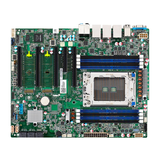
Page 9: Board Image
2.1 Board Image S8020AGM2NR-EX This picture is representative of the latest board revision available at the time of publishing. The board you receive may not look exactly like the above picture. http://www.tyan.com... -
Page 10: Block Diagram
2.2 Block Diagram S8020 Block Diagram http://www.tyan.com... -
Page 11: Motherboard Mechanical Drawing
2.3 Motherboard Mechanical Drawing http://www.tyan.com... -
Page 12: Board Parts, Jumpers And Connectors
The board you receive may not look exactly like the above diagram. The DIMM slot numbers shown above can be used as a reference when reviewing the DIMM population guidelines shown later in the manual. For the latest board revision, please visit our web site at http://www.tyan.com. http://www.tyan.com... - Page 13 25. SYS_FAN_1 (J24) 26. SSI 8-pin CPU and Memory Power Connector 11. M.2 Slot Port 1 (M2_1) (PWRCONN1) 12. TYAN Module Header (DBG_HD1) 27. PSMI Connector (J50) 13. USB3.0 Header (J29) 28. CPU FAN (J27) 29. SSI 8-pin Memory and PCIe Power Connector 14.
- Page 14 COM1: COM Port Header Signal Signal FP_AUDIO_1: Front Audio Header Signal Signal FP_MIC_L AGND FP_MIC_R AUDIO_Detect AUO_HPOUT_R AUO_SENSE_MIC FIO_SENSE AUO_HPOUT_L AUO_SENSE_HP J193: Vertical (Type_A) USB3.0 Connector Signal USB2.0_DATA_N USB2.0_DATA_P USB3.0_RX_N USB3.0_RX_P USB3.0_TX_N USB3.0_TX_P http://www.tyan.com...
- Page 15 SATA_2/3/ SATA_6/7/ SATA_4/5: 14-pin SATA 3.0 Connector Name TYPE GND1 RX1+ RX1- GND2 TX1- TX1+ GND3 GND4 RX2+ RX2- GND5 TX2- TX2+ GND8 J29: USB3.0 Header Signal Signal VCCUSB3_FRONT USB30RX_4N_R USB30RX_4P_R USB30TX_4N_R USB30TX_4P_R USB_PCH DN2_R USB_PCH DP2_R USB_PCH_OC24_N_ID USB_PCH_DP4_R USB_PCH_DN4_R USB30TX_3P_R USB30TX_3N_R USB30RX_3P_R USB30RX_3N_R VCCUSB3_FRONT http://www.tyan.com...
- Page 16 DBG_HD1: TYAN Module Header Signal Signal P3V3 FRAME_N LAD0 LAD1 PLT_RST_N LAD2 LAD3 CLK_24M DBG_SERIRQ DBG_PRES_N 3V3_VSB GPIO1 GPIO2 FPIO1: Front Panel Header Signal Signal LED PWR ID LED PWR LED GND ID LED GND HDD LED PWR HW FAULT...
- Page 17 N/C11 N/C12 N/C13 _1_P (0/3.3V) _0_N PE_RX PE_TX PE_TX Signal N/C14 N/C15 N/C16 _0_P _0_N _0_P PERST# REF_ PEWAKE# REF_ Signal REQ#(I/O) N/C17 (o)(0/3.3V) CLK_N (I/O)(0/3.3V) CLK_P (0/3.3V) Signal N/C18 Signal SUSCLK PEDET 3.3V7 Signal 3.3V8 3.3V9 NC35 NC36 http://www.tyan.com...
- Page 18 J15: BMC COM PORT (RX) Select Jumper Signal Signal BMC_RXD1 U1107 RXD1 BMC_RXD5 1-2: BMC COM Port1(Default) 2-3: BMC COMSOLE Port5 J16: BMC COM PORT (TX) Select Jumper Signal Signal BMC_TXD1 U1107 TXD1 BMC_TXD5 1-2: BMC COM Port1(Default) 2-3: BMC COMSOLE Port5 http://www.tyan.com...
- Page 19 2-3: BMC RESET J19: BUZZER Disable Jumper Signal VCC5 BUZ_1 BUZ_2 Pin 3-4 Closed: Normal Mode (Default) Pin 2-3 Closed: Disable PC Beep Pin 1-4 Closed: Use the External Speaker PWR_BTN1: POWER Button Signal PWR_BTN1 PWR_BTN1 RST_BTN1: Reset Button Signal http://www.tyan.com...
-
Page 20: Led Definitions
B1 error LED The LED shuts off when the DDR status is fine The LED bright to show memory error happened Signal VDD_33_SB memory channel LED32 N18131759 C0 error LED State Description The LED shuts off when the DDR http://www.tyan.com... - Page 21 NGFF1 SSD; Signal VDD_33_RUN NGFF2_LED_L State Description LED_M2 NGFF2_LED The LED shuts off when no NGFF2 SSD insert The LED lights up when Green detect the NGFF2 SSD; Signal VDD_33_DUAL PSU_ALERT_N IPMI_LED1 N18825566 State Description PSU status is abnormal http://www.tyan.com...
- Page 22 PSU status is normal Signal VDD_33_DUAL BMC_HW_FAULT_N On board BMC State Description PSMI_LED2 IPMI ALERT LED HW Sensor status is normal HW Sensor status is abnormal. http://www.tyan.com...
-
Page 23: Installing The Processor And Heatsink
2.6 Installing the Processor and Heatsink The types of processors supported by the S8020 are listed in the 1.2 Hardware Specifications section on page 5. Check our website at http://www.tyan.com ® the latest list of validated AMD processors for this specific motherboard. - Page 24 -) make sure to push the carrier frame with package towards the end of the rail frame until it clicks in place. -) do not drop the carrier frame or touch the package pad to avoid component damage. Using your thumbs and forefinger, remove the PnP cap by lifting it up vertically. http://www.tyan.com...
- Page 25 Carefully close the rail frame with the installed package. Then push both edges of the rail frame firmly until it locks in place. Close the force frame. Then use a T20 Torx screwdriver to tighten the screws to secure the force frame in a sequential order (1->2->3). http://www.tyan.com...
- Page 26 The following diagram illustrates how to install the heatsink on the AMD Ryzen Threadripper Socket: 1. Align and install the CPU heatsink onto the top of the CPU socket. 2. Use a T20 Torx screwdriver to tighten the heatsink screws. http://www.tyan.com...
- Page 27 3. Connect the heatsink power cable to the mainboard connector. http://www.tyan.com...
-
Page 28: Thermal Interface Material
CPU lid (applying too much will actually reduce the cooling). NOTE: Always check with the manufacturer of the heat sink & processor to ensure that the thermal interface material is compatible with the processor and meets the manufacturer’s warranty requirements. http://www.tyan.com... -
Page 29: Tips On Installing Motherboard In Chassis
Be especially careful to look for extra stand-offs. If there are any stand-offs present that are not aligned with a mounting hole on the motherboard, it will likely short components on the back of the motherboard when installed. This will cause malfunction and/or damage to your motherboard. http://www.tyan.com... - Page 30 Some chassis include plastic studs instead of metal. Although the plastic studs are usable, MiTAC recommends using metal studs with screws that will fasten the motherboard more securely in place. Below is a chart detailing what the most common motherboard studs look like and how they should be installed. http://www.tyan.com...
-
Page 31: Installing The Memory
2.9 Installing the Memory Before installing memory, ensure that the memory you have is compatible with the motherboard and processor. Check the TYAN Web site at http://www.tyan.com details of the type of memory recommended for your motherboard. (8) DIMM slots support ... - Page 32 - Use the same # of ranks per DIMM 4. Dual-rank DIMMs are recommended over single-rank DIMMs. AMD SP3R2 Families Support UDIMM Max Freq Support SP3r2 Package Slots DIMMs DIMM Frequency(MT/s) Populated 1.2V 2933 2667 2667 2400 2133 1866 1866 http://www.tyan.com...
- Page 33 Memory Installation Procedure Follow these instructions to install memory modules into the S8020. Unlock a DIMM socket by Press the retaining clip outwardly in the following illustration. Align the memory module with the socket,such that the DIMM NOTCH match the KEY SLOT on the socket.
- Page 34 NOTE: In the area marked red, the PCIe cards or cables must be installed after the memory. http://www.tyan.com...
-
Page 35: Attaching Drive Cables
The following illustrates how to make a SATA Cable connection. If you are in need of SATA/SAS cables or power adapters please contact your local sales representative. 1. SATA drive cable connection 2. SATA drive power connection 3. SATA cable motherboard connector 4. SATA drive power adapter http://www.tyan.com... -
Page 36: Installing Add-In Cards
Doing so allows air to circulate within the chassis more easily, thus improving cooling for all installed devices. NOTE: You must always unplug the power connector from the motherboard before performing system hardware changes to avoid damaging the board or expansion device. http://www.tyan.com... -
Page 37: Connecting External Devices
See the following diagrams for the details. S8020AGM2NR-EX LAN2 LAN1 IPMILAN (i210) (i210) USB2.0 USB3.1 USB3.1 USB3.1 Audio Jack 7.1 VGA Port Gen1 Gen2 Gen1 With S/PDIF Audio Jack Definition http://www.tyan.com... - Page 38 1Gbps LAN Link/Activity LED Scheme Left LED Right LED (Link/Activity) (Speed) No Link Link Green 10 Mbps Active Blinking Green Link Green Solid Green 100 Mbps Active Blinking Green Solid Green Link Green Solid Amber 1Gbps Active Blinking Green Solid Amber http://www.tyan.com...
-
Page 39: Installing The Power Supply
2.13 Installing the Power Supply There are Three (3) power connectors on your S8020 motherboard. The S8020 supports EPS 12V power supply. J22: ATX 24-Pin Power Connector Signal Signal +3.3V_1 +3.3V_4 +3.3V_2 -12V COM_1 COM_4 +5V_1 PS-ON# COM_2 COM_5 +5V_2... -
Page 40: Chapter 3: Bios Setup
Exit current menu <F1> General help <F2> Previous values <F3> Load the Optimal default configuration values of the menu <F4> Save and exit <K> Scroll help area upwards <M> Scroll help area downwards <PgUp> / <PgDn> Move cursor to next/previous page http://www.tyan.com... - Page 41 BIOS menus are continually changing due to continual BIOS updates over the product lifespan of the motherboard. The BIOS menus provided are current as of the date when this manual was written. Please visit TYAN’s website at http://www.tyan.com for information on BIOS updates available for this specific motherboard.
-
Page 42: Main Menu
It displays BIOS related information. Product Name It displays Product information. BIOS Version It displays BIOS version information Build Date and Time It displays the time when built Memory Information It displays the total memory size. Memory Frequency It displays Memory frequency http://www.tyan.com... - Page 43 System Date Set the Date. Use Tab to switch between Date elements. Default Ranges: Year: 2005-2099 Months: 1-12 Days: dependent on month System Time Adjust the system clock. HH (24 hours format): MM (Minutes): SS (Seconds) http://www.tyan.com...
-
Page 44: Advanced Menu
This section facilitates configuring advanced BIOS options for your system. CPU Configuration CPU Configuration parameters Onboard Device Configuration Onboard Device and Function Configuration. PCIE Slot Configuraion Onboard PCIE Slot Configuration Trusted Computing Trusted Computing settings. ACPI Settings System ACPI Parameters Hardware Health Configuration Hardware Health Configuration http://www.tyan.com... - Page 45 PCI, PCI-X and PCI Express Settings USB Configuration USB Configuration Parameters. Network Stack Configuration Network Stack Settings CSM Configuration CSM Configuration, Enable/Disable Option ROM execution setting, etc AMD CBS AMD CBS Setup Page AMD PBS AMD PBS Setup Page http://www.tyan.com...
- Page 46 3.3.1 CPU Configuration SVM Mode Enable/disable CPU virtulization. Disabled / Enabled CPU 0 Information View Information related to CPU 0 Node 0 Information View Memory Information related to Node 0 http://www.tyan.com...
- Page 47 3.3.1.1 Node0 Information Only Read http://www.tyan.com...
- Page 48 Select between onboard or external VGA support. Onboard / External Active Video Slot For external VGA, select VGA on which PCIE# slot to enable NMI Button Enable or disable NMI button. Disabled / Enabled Serial IRQ Mode Configure Serial IRQ Mode Quiet / Continuous http://www.tyan.com...
- Page 49 / x4x4x4x4 PCIE#3 Link width for PCIE#2 x16 / x4x4x4x4 PCIE#5 Link width for PCIE#2 x16 / x4x4x4x4 PCIE#1 Maximum Link Speed for PCIE#1 Gen 1 (2.5 GT/s) / Gen 2 (5 GT/s) / Gen 3 (8 GT/s) / Auto http://www.tyan.com...
- Page 50 Maximum Link Speed for M.2#1 Gen 1 (2.5 GT/s) / Gen 2 (5 GT/s) / Gen 3 (8 GT/s) / Auto M.2#2 Maximum Link Speed for M.2#2 Gen 1 (2.5 GT/s) / Gen 2 (5 GT/s) / Gen 3 (8 GT/s) / Auto http://www.tyan.com...
- Page 51 3.3.4 Trusted Computing Security Device Support Enable or disable BIOS support for security device. O.S. will not show Security device. O.S. will not show Security Device. TCG EFI protocol and INT1A interface will not be available. Enabled / Disabled http://www.tyan.com...
- Page 52 Enables or Disables System ability to Hibernate (OS/S4 Sleep State). This option may not be effective with some operating system. Disabled / Enabled ACPI Sleep State Select the highest ACPI sleep state the system will enter when the SUSPEND button is pressed. Suspend Disabled / S3 (Suspend to RAM) http://www.tyan.com...
- Page 53 When Auto Fan Control was set to [Enabled] PWM Minimal Duty Cycle Item will appear. PWM Minimal Duty Cycle PWM Minimal Duty Cycle BMC Alert Beep Enable/Disable BMC Alert Beep. On / Off PMBus support PMBus Support Disabled / Enabled http://www.tyan.com...
- Page 54 3.3.6.1 Sensor Data Register Monitoring When you enter the Sensor Data Register Monitoring submenu, you will see the following dialog window pop out. Please wait 8~10 seconds. NOTE 1: SDR can not be modified. Read only. http://www.tyan.com...
- Page 55 http://www.tyan.com...
- Page 56 3.3.7 SATA Configuration SATA Mode Select Promontory SATA Type AHCI / RAID / Auto http://www.tyan.com...
- Page 57 3.3.8 AST2500 Configuration Serial Port 1 Configuration Set Parameters of Serial Port 1 (COM1) http://www.tyan.com...
- Page 58 / IO=3F8h, IRQ=3, 4, 5, 6, 7, 9, 10, 11, 12; / IO=2F8h; IRQ=3, 4, 5, 6, 7, 9, 10, 11, 12; / IO=3E8h, IRQ=3, 4, 5, 6, 7, 9, 10, 11, 12; / IO=2E8h, IRQ=3, 4, 5, 6, 7, 9, 10, 11, 12; http://www.tyan.com...
- Page 59 Wake system from S5 Enable or disable system wake on alarm event. Select Fixed time, system will wake on the hr::min::sec specified. Select dynamic time, system will wake on the current time+ increase minute(s) Disabled / Fixed Time / Dynamic Time http://www.tyan.com...
- Page 60 Console Redirection Settings The settings specify how the host computer (which the user is using) will exchange data. Both computers should have the same or compatible settings. NOTE: Console Redirection Settings menu only appear when Console Redirection was set to [Enabled]. http://www.tyan.com...
- Page 61 1’s in the data bits is odd. Mark: parity bit is always 1. Space: parity bit is always 0. Mark and Space parity do not allow for error detection. None / Even / Odd / Mark / Space http://www.tyan.com...
- Page 62 With this mode enabled only text will be sent. This is to capture Terminal data. Disabled / Enabled Resolution 100x31 Enable or disable extended terminal resolution. Disabled / Enabled Putty KeyPad Select FunctionKey and KeyPad on Putty. VT100 / LINUX / XTERMR6 / SCO / ESCN / VT400 http://www.tyan.com...
- Page 63 Bootloader is selected, then Legacy Console Redirection is disabled before booting to legacy OS, when Always Enable is selected, then Legacy Console Redirection is enabled for Legacy OS. Default setting for this option is set to Always Enable. Always Enable / BootLoader http://www.tyan.com...
- Page 64 VT100 / VT100+ / VT-UTF8 / ANSI Bits per Second Select serial port transmission speed. The speed must be matched on the other side. Long or noisy lines may require lower speeds. 9600 / 19200 / 57600 / 115200 http://www.tyan.com...
- Page 65 ‘start’ signal can be sent to restart the flow. Hardware flow control uses two wires to send start/stop signal. None / Hardware RTS/CTS / Software Xon/Xoff Data Bits / Parity / Stop Bits Read only. http://www.tyan.com...
- Page 66 3.3.11 Option ROM Dispatch Policy On Board LAN1 Onboard Device has: UEFI Legacy [X] Embedded ROM(s). VID x8086;DIDx1533 @ s0|Bx3|Dx0|Fx0 Disabled / Enabled On Board LAN2 Onboard Device has: UEFI Legacy [X] Embedded ROM(s). VID x8086;DIDx1533 @ s0|Bx3|Dx0|Fx0 Disabled / Enabled http://www.tyan.com...
- Page 67 Enable or Disable Option ROM execution for selected slot。 Disabled / Enabled PCIE # 4 Empty Enable or Disable Option ROM execution for selected slot。 Disabled / Enabled PCIE # 5 Empty Enable or Disable Option ROM execution for selected slot。 Disabled / Enabled http://www.tyan.com...
- Page 68 Space (Only if System supports 64 bit PCI Decoding). Disabled / Enabled SR-IOV Support If system has SR-IOV capable PCIe devices, this option Enable or Disable Single Root IO virtualization Support. Disabled / Enabled PCI Express Settings Change PCI Express Devices Settings http://www.tyan.com...
- Page 69 Enabled / Disabled USB Mass Storage Driver Support Enable/Disable USB Mass Storage Driver Support. Disabled / Enabled USB transfer time-out The time-out value for Control, Bulk and Interrupt transfers. 1 sec / 5 sec / 10 sec / 20 sec http://www.tyan.com...
- Page 70 Maximum time the device will take before it properly reports itself to the Host Controller. ‘AUTO’ uses default value: for a Root port it is 100 ms, for a Hub port the delay is taken from Hub descriptor. Auto / Manual http://www.tyan.com...
- Page 71 3.3.14 Network Stack Configuration Network Stack Enable/Disable UEFI Network Stack Disabled / Enabled http://www.tyan.com...
- Page 72 Controls the execution of UEFI and legacy Storage OpROM UEFI / legacy / Video Controls the execution of UEFI and legacy Video OpROM UEFI / legacy Other PCI devices Determines OpRom execution policy for devices other than network, storage, or video UEFI / legacy http://www.tyan.com...
- Page 73 3.3.16 AMD CBS http://www.tyan.com...
- Page 74 Core/Thread Enablement SEV-ES ASIO Space Limit SEV VMs using ASIDs below the SEV-ES ASID Space Limit must enable the SEV- ES feature. The valid values for this field are from 0x1 (1) – 0x10 (16) Prefetcher settings Prefetcher settings http://www.tyan.com...
- Page 75 FOUR(4+0) / SIX (3+3) / Auto SMTEN Can be used to disable symmetric multithreading. To re-enable SMT, a POWER CYCLE is needed after selecting the ‘Auto’ option. WARNING – S3 is NOT SUPPORTED on systems where SMT is disabled. Disable / Auto http://www.tyan.com...
- Page 76 Prefether settings Submenu L1 Stream HW Prefetcher Option to Enable | Disable L1 Stream HW Prefetcher Disable / Enable / Auto L2 Stream HW Prefetcher Option to Enable | Disable L1 Stream HW Prefetcher Disable / Enable / Auto http://www.tyan.com...
- Page 77 Controls the memory interleaving size. The valid value are AUTO, 256 bytes, 512 bytes, 1 Kbytes or 2Kbytes. This determines the starting address of the interleave (bit 8,9,10 or 11). 256 Bytes / 512 Bytes / 1 KB / 2 KB / Auto http://www.tyan.com...
- Page 78 3.3.16.3 UMC Common Options Submenu http://www.tyan.com...
- Page 79 3.3.16.3.1 DRAM Memory Mapping Submenu Chipselect Interleaving Interleave memory blocks across the DRAM chip selects for node 0. Disable / Auto BankGroupSwap No help string Enabled / Disabled / Auto http://www.tyan.com...
- Page 80 Manual / Auto ACS Enable Supported functions of Access Control Services Enable / Disabled / Auto PCIe ARI Support Enables Alternative Routing-IO Interpretation Disable / Enable / Auto HD Audio Enable No help string Disable / Enable / Auto http://www.tyan.com...
- Page 81 3.3.16.4.1 NB Configuration Submenu IOMMU Enable/ Disable IOMMU Disabled / Enabled / Auto http://www.tyan.com...
- Page 82 3.3.16.5 FCH Common Options Submenu http://www.tyan.com...
- Page 83 3.3.16.5.1 Ac Power Loss Options Submenu Restore AC Power Loss Select Restore Power Loss Method Power Off / Power On / Last State http://www.tyan.com...
- Page 84 Set PCI-E device aperture range to Auto/40/42/44/46/48 bits limit. [Auto] keeps the platform default settings. Note:Only available when also enable above 4G decode in PCI Setting. Auto / 40 / 42 / 44 / 46 / 48 NVMe RAID mode Enable or disable NVMe RAID mode Disabled / Enabled http://www.tyan.com...
-
Page 85: Chipset Menu
3.4 Chipset Menu Numa Enable or Disable Non uniform Memory Access (NUMA). Disabled / Enabled North Bridge North Bridge Parameters http://www.tyan.com... - Page 86 3.4.1 North Bridge Configuration Memory Configuration Memory Configuration Socket 0 Configuration View Information related to Socket 0 http://www.tyan.com...
- Page 87 3.4.1.1 Memory Configuration Memory Clock This option Allows User to select different memory Clock. Auto /1333MHz / 1600MHz / 1866MHz / 2133MHz / 2400MHz / 2666MHz /2933MHz http://www.tyan.com...
- Page 88 3.4.1.2 Socket 0 Information http://www.tyan.com...
-
Page 89: Server Management
OS Watchdog Timer If enabled, starts a BIOS timer which can only be shut off by management Software after the OS loads. Helps determine that the OS successfully loaded or follows the OS Boot Watchdog Timer policy. Disabled / Enabled http://www.tyan.com... - Page 90 Not available if OS Boot Watchdog Timer is disabled. Do Nothing / Reset / Power Down / Power Cycle BMC Logo Enable or Disable BMC logo Disabled / Enabled System Event Log Press<Enter> to change the SEL event log configuration. BMC network configuration Configure BMC network parameters http://www.tyan.com...
- Page 91 Choose options for reactions to a full SEL. Do Nothing / Erase Immediately Log EFI Status Codes Disable the logging of EFI Status Codes or log only error code or only progress code or both. Disabled / Both / Error Code / Progress Code http://www.tyan.com...
- Page 92 3.5.2 BMC Network Configuration Submenu http://www.tyan.com...
- Page 93 Management Port 2 Enable/Disable BMC Share NIC Disabled / Enabled Configure IPV6 support Management Port 1 IPV6 Support Enable or Disable LAN1 IPV6 Support Disabled / Enabled Management Port 2 IPV6 Support Enable or Disable LAN2 IPV6 Support Disabled / Enabled http://www.tyan.com...
-
Page 94: Security
Enable or disable HDD security freeze lock. Disable to support secure erase function. Disabled / Enabled (When with install M.2 NVMe or PCIe NVMe, the below item will appear. For examples: INTEL SSDEKKW020TB.) TCG Storage device Security Configuration >INTEL SSDPEKKW020TB >INTEL SSDPEKKW020TB http://www.tyan.com... - Page 95 INTEL SSDPEKKW020TB Submenu Set Admin Password Sets Admin Password. Once installed enables device security and locks device immediately. Advisable to Power Cycle System after Password Set/Clear. Discard or Save changes option in setup does not have any impact on PASSWORD controls. http://www.tyan.com...
-
Page 96: Boot
Enables or disables Quiet Boot option. Disabled / Enabled Endless Boot Enabled or Disabled Endless boot. Enabled / Disabled Wait for “ESC” if Error Enable or Disable wait ESC key stop when BIOS has error appeared. Disabled / Enabled http://www.tyan.com... - Page 97 Boot Option #1 Boot Option #2 Sets the system boot order. Device Name / Disabled Hard Drive BBS Priorities Set the order of the legacy devices in this group Delete Boot Option Remove an EFI boot option from the boot order http://www.tyan.com...
- Page 98 3.7.1 Delete Boot Option Configuration Delete Boot Option Remove an EFI boot option from the boot order. Device Name / Select one to Delete http://www.tyan.com...
-
Page 99: Save & Exit
Reset system setup without saving any changes. Save Changes Save changes done so far to any of the setup options. Discard Changes Discard changes done so far to any of the setup options. Restore Defaults Restore/Load Default values for all the setup options. http://www.tyan.com... - Page 100 Save as User Defaults Save the changes done so far as User Defaults. Restore User Defaults Restore the User Defaults to all the setup options. Boot Override Device Name http://www.tyan.com...
-
Page 101: Chapter 4: Diagnostics
BIOS flash failure, you must contact your dealer for a replacement BIOS. There are no exceptions. TYAN does not have a policy for replacing BIOS chips directly with end users. In no event will TYAN be held responsible for damages done by the end user. -
Page 102: Ami Bios Post Code (Aptio)
South Bridge initialization before microcode loading 0x05 OEM initialization before microcode loading 0x06 Microcode loading 0x07 AP initialization after microcode loading 0x08 North Bridge initialization after microcode loading 0x09 South Bridge initialization after microcode loading 0x0A OEM initialization after microcode loading 0x0B Cache initialization http://www.tyan.com... - Page 103 Memory initialization. Configuring memory 0x2F Memory initialization (other) 0x30 Reserved for ASL (see ASL Status Codes section below) 0x31 Memory Installed 0x32 CPU post-memory initialization is started. 0x33 CPU post-memory initialization. Cache initialization CPU post-memory initialization. Application Processor(s) (AP) 0x34 initialization http://www.tyan.com...
- Page 104 S3 Resume Progress Codes 0xE0 S3 Resume is started (S3 Resume PPI is called by the DXE IPL). 0xE1 S3 Boot Script execution 0xE2 Video repost 0xE3 OS S3 wake vector call 0xE4 – 0xE7 Reserved for future AMI progress codes http://www.tyan.com...
- Page 105 DXEIPL was not found. DXE Core Firmware Volume was not found. Recovery failed S3 Resume failed Reset PPI is not available. DXE Phase Status Code Description 0x60 DXE Core is started. 0x61 NVRAM initialization 0x62 Installation of the South Bridge Runtime Services http://www.tyan.com...
- Page 106 PCI Bus Hot Plug Controller initialization 0x94 PCI Bus Enumeration 0x95 PCI BUS Request Resources 0x96 PCI Bus Assign Resources 0x97 Console output devices connect 0x98 Console Input devices connect 0x99 Super IO initialization 0x9A USB initialization is started. http://www.tyan.com...
- Page 107 0xC0 – 0xCF OEM BDS initialization codes DXE Error Codes 0xD0 CPU initialization error 0xD1 North Bridge initialization error 0xD2 South Bridge initialization error 0xD3 Some of the Architectural Protocols are not available 0xD4 PCI resource allocation error. Out of Resources http://www.tyan.com...
- Page 108 System is waking up from the S3 sleep state. 0x40 System is waking up from the S4 sleep state. System has transitioned into ACPI mode. Interrupt controller is in 0xAC APIC mode. System has transitioned into ACPI mode. Interrupt controller is in 0xAA APIC mode. http://www.tyan.com...
-
Page 109: Amd Bios Post Code
TpProcMemSystemMemoryMapping = 0xE010, ///< ProcMemSystemMemory Mapping TpProcMemMtrrConfiguration = 0xE011, ///< ProcMemMtrrConfiguration TpProcMemDramTraining = 0xE012, ///< ProcMemDramTraining TpProcMemBeforeAnyTraining = 0xE013, ///< ProcMemBefore AnyTraining(Publicinterface) // PMU Test Points TpProcMemPmuBeforeFirmwareLoa = 0xE014, ///< ABL Mem - PMU - Before PMU Firmware load http://www.tyan.com... - Page 110 = 0xE027, ///< ABL Mem - PMU Complete TpProcMemAfterPmuTraining = 0xE028, ///< ABL Mem - PMU - After PMU Training TpProcMemBeforeDisablePmu = 0xE029, ///< ABL Mem - PMU - Before Disable PMU //Original Post code TpProcMemTransmitDqsTraining = 0xE02A, ///< ABL Mem - ProcMemTransmitDqsTraining http://www.tyan.com...
- Page 111 = 0xE03E, ///< ABL Mem - Before callout for "AgesaReadSpd" TpProcMemAfterAgesaReadSpd = 0xE03F, ///< ABL Mem - After callout "AgesaReadSpd" TpProcMemBeforeAgesaHookBefore = 0xE040, ///< ABL Mem - Before DramInit optional callout "AgesaHookBeforeDramInit" TpProcMemAfterAgesaHookBeforeD = 0xE041, ///< ABL Mem - After http://www.tyan.com...
- Page 112 TpProcCpuInitAfterTrainingEnd = 0xE052, ///< Exit point CPU init after training TpProcCpuApobCcxMapInitStart = 0xE053, ///< Entry point CPU APOB map init TpProcCpuApobCcxMapInitEnd = 0xE054, ///< Exit point CPU APOB CCX map init TpProcCpuOptimizedBootStart = 0xE055, ///< Entry point CPU Optimized http://www.tyan.com...
- Page 113 = 0xE08A, ///< Configure DCT For aining training begin TpProcMemConfigureDCTNonExplici = 0xE08B, ///< Configure DCT For Non- tSeq Explicit TpProcMemSynchronizeChannels = 0xE08C, ///< Configure to Sync channels TpProcMemC6StorageAllocation = 0xE08D, ///< Allocate C6 Storage TpProcMemLvDdr4 = 0xE08E, ///< Before LV DDR4 http://www.tyan.com...
- Page 114 = 0xE0B2, ///< ABL 1 DF Early TpAbl1DfPreTraining = 0xE0B3, ///< ABL 1 DF Pre Training TpAbl1DebugSync = 0xE0B4, ///< ABL 1 Debug Synchronization TpAbl1ErrorDetected = 0xE0B5, ///< ABL 1 Error Detected TpAbl1GlobalMemErrorDetected = 0xE0B6, ///< ABL 1 Global memory detected error http://www.tyan.com...
- Page 115 TpAbl3GmiGopInitStage5 = 0xE5C0, ///< ABL 3 GMI/xGMI Initialization Stage 5 TpAbl3GmiGopInitStage5Warning = 0xB5C0, ///< ABL 3 GMI/xGMI Initialization Stage 5 Warning TpAbl3GmiGopInitState5Error = 0xF5C0, ///< ABL 3 GMI/xGMI Initialization Stage 5 Error TpAbl3GmiGopInitStage6 = 0xE6C0, ///< ABL 3 GMI/xGMI http://www.tyan.com...
- Page 116 TpAbl4GmicieTraining = 0xE0CC, ///< ABL 4 Gmi Pcie Training - boot cold TpAbl4ColdEnd = 0xE0CD, ///< ABL 4 Cold boot End TpAbl4ResumeInitialization = 0xE0CE, ///< ABL 4 Initialization - Resume boot TpAbl4ResumeEnd = 0xE0CF, ///< ABL 4 Resume End http://www.tyan.com...
- Page 117 = 0xE0E5, ///< After the heap manager calls out to deallocate a buffer TpIfBeforeLocateHeapBuffer = 0xE0E6, ///< Before the heap manager calls out to locate a buffer TpIfAfterLocateHeapBuffer = 0xE0E7, ///< After the heap manager calls out to locate a buffer http://www.tyan.com...
- Page 118 = 0xE0F9, ///< Failed PMU training. TpProcMemPhase1End = 0xE0FA, ///< End of phase 1 memory code TpProcMemPhase2End = 0xE0FB, ///< End of phase 2 memory code // ABL0 test points TpAbl0Begin = 0xE0FC, ///< Abl0Begin TpAbl0End = 0xE0FD, ///< ABL 0 End http://www.tyan.com...
- Page 119 = 0xE2A9, ///< ABL Error for DDR Post Package Repair No PPR Table Heap Aloc error TpAblErrorEccMemAutoHeapAlocErr = 0xE2AA, ///< ABL Error for Ecc Mem Auto Aloc Error error TpAblErrorSocScanHeapAlocError = 0xE2AB, ///< ABL Error for Soc Scan Heap Aloc error http://www.tyan.com...
- Page 120 = 0xE2BD, ///< ABL Error for Flow P2 Family Supprot error TpAblErrorHeapDealocForPmuSram = 0xE2BE, ///< ABL Error for Heap MsgBlock Deallocation for PMU Sram Msg Block error TpAblErrorDdrRecovery Recovery error = 0xE2BF, ///< ABL Error for DDR TpAblErrorRrwTest = 0xEBC0, ///< ABL Error for RRW Test http://www.tyan.com...
- Page 121 General Error TpAblErrorAbl2GenError = 0xE2D2, ///< ABL Error for ABL2 General Error TpAblErrorAbl3GenError = 0xE2D3, ///< ABL Error for ABL3 General Error TpAblErrorAbl5GenError = 0xE2D4, ///< ABL Error for ABL4 General Error TpAblErrorOverClockMemInit = 0xE2D5, ///< ABL Error over clock http://www.tyan.com...
- Page 122 Allocation Error TpAblErrorMbistResultsError = 0xE2EC, ///< ABL Error MBIST Results Error TpAblErrorNoDimmSmbusInfoError = 0xE2ED, ///< ABL Error NO Dimm Smcus Info Error TpAblErrorPorMaxFreqTblError = 0xE2EE, ///< ABL Error Por Max Freq Table Error TpAblErrorUnsupportedDimmConfugl = 0xE2EF, ///< ABL Error http://www.tyan.com...
- Page 123 = 0xE301, ///< ABL Error ABL 2 Mem Init Error TpAblErrorAbl4MemInitError = 0xE302, ///< ABL Error ABL 4 Mem Init Error TpAblErrorAbl6MemInitError = 0xE303, ///< ABL Error ABL 6 Mem Init Error TpAblErrorAbl1ErrorReportError = 0xE304, ///< ABL Error ABL 1 error repor Error http://www.tyan.com...
- Page 124 REsults Rx Vref captured TpAblMemAlertPmuResultsTxVref = 0xE315, ///< ABL Alert PMU REsults Tx Vref captured TpAblErrorNoMemoryAvailableInSyst = 0xE316, ///< ABL Error No memory available in system TpAblApcbLoadError = 0xEACB, ///< ABL Alert APCB Failed to Load EndAgesaTps = 0xEFFF, ///< EndAgesas http://www.tyan.com...
- Page 125 = 0xA10D, ///< (Public interface) TpProcMemPhyFenceTraining = 0xA10E, ///< TpProcMemPhyFenceTraining TpProcMemSynchronizeDcts = 0xA10F, ///< TpProcMemSynchronizeDcts TpProcMemSystemMemoryMapping = 0xA110, ///< TpProcMemSystemMemoryMapping TpProcMemMtrrConfiguration = 0xA111, ///< TpProcMemMtrrConfiguration TpProcMemDramTraining = 0xA112, ///< TpProcMemDramTraining TpProcMemBeforeAnyTraining = 0xA113, ///< (Public interface) TpProcMemWriteLevelizationTraining = 0xA114, ///< http://www.tyan.com...
- Page 126 = 0xA133, ///< Start sweep TpProcMemMaxRdLatSetDelay = 0xA134, ///< Set delay TpProcMemMaxRdLatWritePattern = 0xA135, ///< Write test pattern TpProcMemMaxRdLatReadPattern = 0xA136, ///< Read Test pattern TpProcMemMaxRdLatTestPattern = 0xA137, ///< Compare Test pattern TpProcMemOnlineSpareInit = 0xA138, ///< Online Spare init http://www.tyan.com...
- Page 127 = 0xA184, ///< Continuous Pattern Read TpProcMemContinPatternGenWrite = 0xA185, ///< Continuous Pattern Write TpProcMem2dRdDqsTraining = 0xA186, ///< Mem: 2d RdDqs Training begin TpProcMemBefore2dTrainExtVrefCha = 0xA187, ///< Mem: Before optional callout to platform BIOS to change External Vref during 2d Training http://www.tyan.com...
- Page 128 TpBrInitLateEnd = 0xA1A1, ///< BR Init Late end TpBrDxeInstallCompleteProtocol = 0xA1A2, ///< BR DXE install complete protocol TpUnbInstallCompletePpi = 0xA1A3, ///< UNB install complete TpUnbAfterApLaunchCallbackEntry = 0xA1A4, ///< UNB AfterApLaunch callback entry TpUnbAfterApLaunchCallbackEnd = 0xA1A5, ///< UNB AfterApLaunch http://www.tyan.com...
- Page 129 = 0xA502, ///< PspPeiV1 exit TpPspPeiV1MemDiscoveredPpiCallba = 0xA503, ///< ckEntry MemoryDiscoveredPpiCallback entry TpPspPeiV1MemDiscoveredPpiCallba = 0xA504, ///< ckExit MemoryDiscoveredPpiCallback exit TpPspDxeV1Entry = 0xA507, ///< PspDxeV1 entry TpPspDxeV1Exit = 0xA508, ///< PspDxeV1 exit TpPspDxeV1PciCallbackEntry = 0xA50A, ///< PspDxeV1 PspPciEnumerationCompleteCallBack entry TpPspDxeV1PciCallbackExit = 0xA50B, ///< PspDxeV1 http://www.tyan.com...
- Page 130 = 0xA529, ///< PspDxeV2 ready to boot entry TpPspDxeV2RTBCallbackExit = 0xA52A, ///< PspDxeV2 ready to boot exit TpPspDxeV2ExitBsCallbackEntry = 0xA52B, ///< PspDxeV2 exit boot serivce entry TpPspDxeV2ExitBsCallbackExit = 0xA52C, ///< PspDxeV2 exit boot serivce exit TpPspSmmV2Entry = 0xA52D, ///< PspSmmV2 entry http://www.tyan.com...
- Page 131 TpPspP2CmboxSpiWriteFVEntry = 0xA595, ///< PspP2Cmbox Command SpiWriteFV Handling entry TpPspP2CmboxSpiEraseFVEntry = 0xA596, ///< PspP2Cmbox Command SpiEraseFV Handling entry TpPspP2CmboxCmdExit = 0xA59E, ///< PspP2Cmbox Command Handling exit TpPspP2CmboxCmdFailExit = 0xA59F, ///< PspP2Cmbox Command Handling Fail exit // C2P mailbox Handling http://www.tyan.com...
- Page 132 MboxBiosCmdSleep SxInfo finished TpPspC2PmboxWaitCmdRsmInfo = 0xA5D4, ///< Wait C2P command MboxBiosCmdRsmInfo finished TpPspC2PmboxWaitCmdQueryCap = 0xA5D5, ///< Wait C2P command MboxBiosCmdQueryCap finished TpPspC2PmboxWaitCmdBootDone = 0xA5D6, ///< Wait C2P command MboxBiosCmdBootDone finished TpPspC2PmboxWaitCmdClearS3Sts = 0xA5D7, ///< Wait C2P command MboxBiosCmdClearS3Sts finished http://www.tyan.com...
- Page 133 = 0xA904, ///< AmdNbioPcie PEIM driver entry TpNbioPCIePeiExit = 0xA905, ///< AmdNbioPcie PEIM driver exit TpNbioPCIeDxeEntry = 0xA906, ///< AmdNbioPcie DXE driver entry TpNbioPCIeDxeExit = 0xA907, ///< AmdNbioPcie DXE driver exit // GFX TpNbioGfxPeiEntry = 0xA908, ///< AmdNbioGfx PEIM driver http://www.tyan.com...
- Page 134 = 0xA918, ///< AmdSmuV10 PEIM driver entry TpNbioSmuV10PeiExit = 0xA919, ///< AmdSmuV10 PEIM driver exit TpNbioSmuV10DxeEntry = 0xA91A, ///< AmdSmuV10 DXE driver entry TpNbioSmuV10DxeExit = 0xA91B, ///< AmdSmuV10 DXE driver exit // IOMMU PEIM TpNbioIommuPEIEntry = 0xA920, ///< AmdNbioIommu PEIM driver entry http://www.tyan.com...
- Page 135 = 0xA95A, ///< AmdPcieMiscInit Event entry TpAmdPcieMiscInitExit = 0xA95B, ///< AmdPcieMiscInit Event exit TpNbioBaseHookReadyToBootEntry = 0xA95C, ///< NbioBaseHookReadyToBoot Event entry TpNbioBaseHookReadyToBootExit = 0xA95D, ///< NbioBaseHookReadyToBoot Event exit TpNbioBaseHookPciIOEntry = 0xA95E, ///< NbioBaseHookPciIO Event entry TpNbioBaseHookPciIOExit = 0xA95F, ///< NbioBaseHookPciIO Event exit http://www.tyan.com...
- Page 136 = 0xA985, ///< GfxConfigEnvInterface exit TpGfxEnvInterfaceCZEntry = 0xA986, ///< GfxEnvInterfaceCZ entry TpGfxEnvInterfaceCZExit = 0xA987, ///< GfxEnvInterfaceCZ exit TpGfxMidInterfaceCZEntry = 0xA988, ///< GfxMidInterfaceCZ entry TpGfxMidInterfaceCZExit = 0xA989, ///< GfxMidInterfaceCZ exit TpGfxIntInfoTableInterfaceCZEntry = 0xA98A, ///< GfxIntInfoTableInterfaceCZ entry TpGfxIntInfoTableInterfaceCZExit = 0xA98B, ///< http://www.tyan.com...
- Page 137 = 0xAC70, ///< CCX PEI start to launch APs for S3 TpCcxPeiEndLaunchApsForS3 = 0xAC71, ///< CCX PEI end of launching APs for S3 TpCcxDxeStartLaunchAp = 0xAC90, ///< CCX start to launch AP TpCcxDxeEndLaunchAp = 0xAC91, ///< CCX launch AP is ended http://www.tyan.com...
- Page 138 = 0xAF01, ///< FCH InitReset dispatch point TpFchInitEnvDispatching = 0xAF06, ///< FCH InitEnv dispatch point TpFchInitMidDispatching = 0xAF07, ///< FCH InitMid dispatch point TpFchInitLateDispatching = 0xAF08, ///< FCH InitLate dispatch point TpFchInitS3EarlyDispatching = 0xAF0B, ///< FCH InitS3Early dispatch point http://www.tyan.com...
- Page 139 = 0xAF58, ///< FCH InitEnv USB TpFchInitEnvXgbe = 0xAF59, ///< FCH InitEnv xGbE TpFchInitEnvHwAcpiP = 0xAF5F, ///< FCH InitEnv HwAcpiP TpFchInitMidHwAcpi = 0xAF60, ///< FCH InitMid HwAcpi TpFchInitMidAb = 0xAF61, ///< FCH InitMid AB Link TpFchInitMidLpc = 0xAF62, ///< FCH InitMid LPC http://www.tyan.com...
- Page 140 = 0xAF79, ///< FCH InitLate xGbE TpFchPTLoadFWEntry = 0xAF7A, ///< FCH PT load FW Entry TpFchPTLoadFWExit = 0xAF7B, ///< FCH PT load FW Exit EndFchTestPoints = 0xAFFF, ///< End of TP range for EndAgesaPcs = 0xFFFF, ///< Last defined AGESA http://www.tyan.com...
-
Page 141: Chapter 5: Configuring A Raid Set
NOTE2: An M.2 PCIe SSD cannot be used to set up a RAID set either with an M.2 SATA SSD or a SATA hard drive. NOTE3: Refer to "Internal Connectors," for the installation notices for the M.2, and SATA connectors. http://www.tyan.com... - Page 142 (Power-On Self-Test). Under Advance, Set SATA Mode to RAID (Figure 1). Then save the settings and restart your computer. (Under AMD PBS ,If you want to use NVMe PCIe SSDs to confgure RAID, make sure to set NVMe RAID mode to Enabled.) Figure 1 http://www.tyan.com...
- Page 143 C. UEFI RAID Confguration Step 1: In Advance Setup, go to BIOS and set CSM Support to Enabled (Figure 2). Save the changes and exit BIOS Setup. And set Storage to UEFI. Figure 2 http://www.tyan.com...
- Page 144 Step 2: After the system reboot, enter BIOS Setup again. Then enter the RAIDXpert2 Confguration Utility sub-menu (Figure 3). Figure 3 http://www.tyan.com...
- Page 145 (Figure 4). RAID levels supported include RAID 0, RAID 1, and RAID10 (Figure 5) (the selections available depend on the number of the hard drives being installed). Next, press <Enter> on Select Physical Disks to enter the Select Physical Disks screen. Figure 4 http://www.tyan.com...
- Page 146 Figure 5 http://www.tyan.com...
- Page 147 RAID array and set them to Enabled. Next, use the down arrow key to move to Apply Changes and press <Enter> (Figure 6).Then return to the previous screen and set the Array Size, Array Size Unit, Read Cache Policy and Write Cache Policy. Figure 6 http://www.tyan.com...
- Page 148 Step 5: After setting the capacity, move to Create Array and press <Enter> to begin. (Figure Figure 7 http://www.tyan.com...
- Page 149 After completing, you'll be brought back to the Array Management screen. Under Manage Array Properties you can see the new RAID volume and information on RAID level, array name, array capacity, etc. (Figure 8) Figure 8 http://www.tyan.com...
- Page 150 To delete a RAID array, select the array to be deleted on the RAIDXpert2 Confguration Utility\ArrayManagement\Delete Array screen. Press <Enter> on Delete Array to enter the Delete screen. Then set Confrm to Enabled and press <Enter> on Yes (Figure 9). Figure 9 http://www.tyan.com...
-
Page 151: Chapter 6 Windows : Install Amd-Raid Uefi Drivers During Windows Os Installation
• Click Next • Click Install Now or similar • If prompted, select the desired Operating System • Click Next • Insert the storage medium with the AMD-RAID drivers into the USB port or applicable system drive. • Click Browse http://www.tyan.com... - Page 152 • Navigate to the directory containing the saved AMD-RAID drivers • Click OK Note: If the installation has multiple controllers, there will be two or more rcbottom.inf’s listed. http://www.tyan.com...
- Page 153 • Select the first AMD-RAID Bottom Device (rcbottom.inf) driver in the list • Click Next 5. At the Load Driver Warning message • Click OK 6. At the Select the Driver to install window • Click Browse • Navigate to the directory containing the saved AMD-RAID drivers • Click OK http://www.tyan.com...
- Page 154 • Select the AMD-RAID Controller (rcraid.inf) driver in the list • Click Next • Select (Check Mark) I Accept the License Terms • Click Next • Select Custom: Install Windows Only (advanced) or similar http://www.tyan.com...
- Page 155 • Navigate to the directory containing the saved AMD-RAID drivers • Click OK • Select the AMD-RAID Config Device (rccfg.inf) driver from the list • Click Next 8. At the Where do you want to install Windows • Click Next http://www.tyan.com...
- Page 156 • Expand System Devices: there will be an entry listed as AMD-RAID Config Device 11. Remove the storage medium and Microsoft Windows OS CD-ROM or DVD from the applicable drive(s) or port. 12. Proceed Installing the AMD RAIDXpert2 Management Suite for Windows®, Refer to Chapter 6. http://www.tyan.com...
-
Page 157: Appendix I: Fan And Temp Sensors
(rpm) Temp Sensor: P_DIM_MOS_2_Area ,and MB_Air_Inlet etc. They detect the system temperature around. NOTE: The system temperature is measured in a scale defined by AMD, not in Fahrenheit or Celsius. http://www.tyan.com... - Page 158 BIOS Temp Sensor Name Explanation: http://www.tyan.com...
- Page 159 The highest temperature of CPU0 D1 UMC1 channel D slot BIOS FAN Sensor Name Explanation CPU_FAN Fan speed of CPU_FAN SYS_FAN_1 Fan speed of SYS_FAN_1 SYS_FAN_2 Fan speed of SYS_FAN_2 SYS_FAN_3 Fan speed of SYS_FAN_3 SYS_FAN_4 Fan speed of SYS_FAN_4 SYS_FAN_5 Fan speed of SYS_FAN_5 http://www.tyan.com...
- Page 160 NOTE http://www.tyan.com...
- Page 161 (reading to or writing from a disk drive a single time is much faster than doing so repeatedly) there is the possibility of losing your data should the system crash. Information in a buffer is temporarily stored, not permanently saved. http://www.tyan.com...
- Page 162 (like soundcards or keyboards) to access the main memory without involving the CPU. This frees up CPU resources for other tasks. As with IRQs, it is vital that you do not double up devices on a single line. Plug-n-Play devices will take care of this for you. http://www.tyan.com...
- Page 163 ROM chip which can, unlike normal ROM, be updated. This allows you to keep ® ’s up with changes in the BIOS programs without having to buy a new chip. TYAN BIOS updates can be found at http://www.tyan.com ESCD (Extended System Configuration Data): a format for storing information about Plug-n-Play devices in the system BIOS.
- Page 164 PXE (Preboot Execution Environment): one of four components that together make up the Wired for Management 2.0 baseline specification. PXE was designed to define a standard set of preboot protocol services within a client with the goal of allowing networked-based booting to boot using industry standard protocols. http://www.tyan.com...
- Page 165 NVIDIA s (graphics communications processing units) and NVIDIA MCPs (media and processors). application Depending on the , NVIDIA SLI can deliver as much as two times the performance of a single GPU configuration. http://www.tyan.com...
- Page 166 CPUs without damaging the sensitive CPU pins. The CPU is lightly placed in an open ZIF socket, and a lever is pulled down. This shifts the processor over and down, guiding it into the board and locking it into place. http://www.tyan.com...
- Page 167 "TYAN's tech support is some of the most impressive we've seen, with great response time and exceptional organization in general" - Anandtech.com Help Resources: 1. See the beep codes section of this manual.
- Page 168 (RMA) number. The RMA number Should be prominently displayed on the outside of the shipping carton and the package should be mailed prepaid. ® TYAN will pay to have the board shipped back to you. Notice for the USA Compliance Information Statement (Declaration of...
Need help?
Do you have a question about the S8020 and is the answer not in the manual?
Questions and answers