Table of Contents
Advertisement
Copyright
Copyright © 2010 MiTAC International Corporation. All rights reserved. No part of
this manual may be reproduced or translated without prior written consent from
MiTAC International Corporation.
Trademark
All registered and unregistered trademarks and company names contained in this
manual are property of their respective owners including, but not limited to the
following.
®
TYAN
is a trademark of MiTAC International Corporation.
®
AMD
is a trademark of AMD
®
Intel
is a trademark of Intel
AMI, AMI BIOS are trademarks of AMI Technologies.
®
Microsoft
, Windows
®
Winbond
is a trademark of Winbond Electronics Corporation.
Notice
Information contained in this document is furnished by MiTAC International
Corporation and has been reviewed for accuracy and reliability prior to printing.
MiTAC assumes no liability whatsoever, and disclaims any express or implied
warranty, relating to sale and/or use of TYAN
warranties relating to fitness for a particular purpose or merchantability. MiTAC
retains the right to make changes to product descriptions and/or specifications at
any time, without notice. In no event will MiTAC be held liable for any direct or
indirect, incidental or consequential damage, loss of use, loss of data or other
malady resulting from errors or inaccuracies of information contained in this
document.
S8230
Version 1.01
®
Corporation.
®
Corporation.
®
are trademarks of Microsoft Corporation.
®
products including liability or
Advertisement
Table of Contents

Related Manuals for TYAN S8230


Summary of Contents for TYAN S8230
- Page 1 Corporation and has been reviewed for accuracy and reliability prior to printing. MiTAC assumes no liability whatsoever, and disclaims any express or implied ® warranty, relating to sale and/or use of TYAN products including liability or warranties relating to fitness for a particular purpose or merchantability. MiTAC retains the right to make changes to product descriptions and/or specifications at any time, without notice.
- Page 2 http://www.tyan.com...
-
Page 3: Table Of Contents
3.6 Security Menu .................. 70 3.7 Chipset Menu .................. 72 3.8 Exit Menu ..................80 Chapter 4: Diagnostics ................82 4.1 Beep Codes ..................82 4.2 Flash Utility ..................82 4.3 AMIBIOS Post Code ................ 83 Glossary ..................... 86 http://www.tyan.com... -
Page 4: Before You Begin
The retail motherboard package should contain the following: 1x S8230 Motherboard 6 x Serial ATA Cable 1 x USB2.0 cable 1 x S8230 User’s manual 1 x S8230 Quick reference guide ® 1 x TYAN Driver CD 1 x I/O shield 2 x mini SAS Cable http://www.tyan.com... -
Page 5: Chapter 1: Instruction
IT environments. ® Remember to visit the TYAN website at http://www.tyan.com. There you can ® find all the information on all TYAN products as well as all the supporting documentation, FAQs, Drivers and BIOS upgrades. 1.2 S8230 Hardware Specifications Supported CPU... - Page 6 AST2050 IPMI IPMI 2.0 compliant baseboard management Server Feature controller (BMC) / USB 2.0 virtual hub Management AST2050 iKVM 24-bit high quality video compression / Dual Feature 10/100 Mb/s MAC interfaces BIOS Brand / ROM size AMI / 4MB http://www.tyan.com...
- Page 7 RoHS RoHS 6/6 Complaint Yes Motherboard (1) S8230 Motherboard Manual (1) User's manual / (1) Quick Ref. Guide Installation CD (1) TYAN installation CD Package Contains I/O Shield (1) I/O Shield SATA (6) SATA signal cables Cable (2) mini-SAS cables (for S8230WGM4NR and...
-
Page 8: Software Specifications
BMC (AST2050) LSA2008 SAS Memory DIMM PCIE Slots SATAII Ports 1.3 Software Specifications ® For OS (operation system) support, please check with TYAN support for latest information. Remember to visit our Web site at http://www.tyan.com for the latest AST2050 User’s Guide. -
Page 9: Chapter 2: Board Installation
(5) Inspect the board for damage. The following pages include details on how to install your motherboard into your chassis, as well as installing the processor, memory, disk drives and cables. NOTE: Do not apply power to the board if it has been damaged. http://www.tyan.com... -
Page 10: Board Image
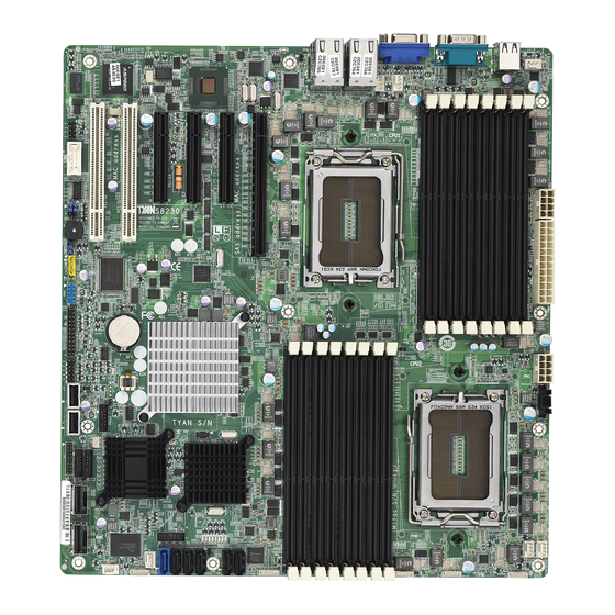
2.1 Board Image This picture is representative of the latest board revision available at the time of publishing. The board you receive may not look exactly like the above picture. http://www.tyan.com... -
Page 11: Block Diagram
2.2 Block Diagram S8230 Block Diagram http://www.tyan.com... -
Page 12: Board Parts, Jumpers And Connectors
The board you receive may not look exactly like the above diagram. But for the DIMM number please refer to the above placement for memory installation. For the latest board revision, please visit our web site at http://www.tyan.com. http://www.tyan.com... - Page 13 CPU0 Memory Voltage Select Jumper JP22 CPU1 Memory Voltage Select Jumper JP23 LAN4 Active LED JP24 LAN2 Active LED JP25 ID LED Header Jumper Legend OPEN - Jumper OFF Without jumper cover CLOSED - Jumper ON With jumper cover http://www.tyan.com...
- Page 14 http://www.tyan.com...
- Page 15 TACH1 TACH2 +12V PWM2 NOTE: Do not mix 8-pin Fan headers with 4-pin Fan headers. Mixing these fan headers will cause problems to the system. J93: 2x10-Pin FAN connector for TYAN (Barebones use only) Signal Signal FANIN1 FANIN6 FANIN2 FANIN7...
- Page 16 USB1 http://www.tyan.com...
- Page 17 Fault LED HD LED - PSU Fault LED Power SW LAN1 LED + LAN1 LED - Reset SW SMB Host Data SMB Host CLK ID SW INTRU# TEMP Sensor LAN3 LED + LAN3 LED - J8: COM2 Connector Signal Signal http://www.tyan.com...
- Page 18 JP25 LED1 JP24 JP23 http://www.tyan.com...
- Page 19 P3V3_AUX ID_SW_L State Color Description Blue System identified System not identified NOTE: IPMI can activate ID LED from remote site. Please visit the TYAN Web Site at http://www.tyan.com to download the latest AST2050 Software Configuration Guide for IPMI settings. http://www.tyan.com...
- Page 20 http://www.tyan.com...
- Page 21 1. Power off system and disconnect both power connectors from the motherboard. 2. Put jumper cap back to Pin_1 and Pin_2 (default setting). 3. Use jumper cap to close Pin_2 and Pin_3 for seconds to Clear CMOS. Clear CMOS 4. Reconnect power & power on system. http://www.tyan.com...
- Page 22 JP21 JP22 JP13 JP19 JP16 http://www.tyan.com...
- Page 23 Open: Support regular 1.5V DDR3 memory (Default) Closed: Support for Low Voltage 1.35V DDR3 memory JP22: Low Voltage (1.35V) DDR3 Enable/Disable for CPU1 Jumper Open: Support regular 1.5V DDR3 memory (Default) Closed: Support for Low Voltage 1.35V DDR3 memory http://www.tyan.com...
-
Page 24: Installing The Processor And Heat Sink
2.4 Installing the Processor and Heat sink ® The S8230 supported AMD processors are listed in section 1.2 S8230 Hardware Specifications on page 4. Check our website at http://www.tyan.com for latest processor support. NOTE: MiTAC is not liable for damage as a result of operating an unsupported configuration. - Page 25 Lift the socket cover to a fully open position. Take off the CPU protection cap. Place the CPU in the CPU socket. http://www.tyan.com...
- Page 26 Place the heat sink on top of the CPU and secure it to the motherboard with 2 screws. Connect the heat sink Fan cable to the CPU0 FAN connector J55. Repeat the same procedures to install the second heat sink (CPU1 FAN Connector J9). http://www.tyan.com...
-
Page 27: Thermal Interface Material
CPU lid (applying too much will actually reduce the cooling). NOTE: Always check with the manufacturer of the heat sink & processor to ensure that the thermal interface material is compatible with the processor and meets the manufacturer’s warranty requirements. http://www.tyan.com... -
Page 28: Tips On Installing Motherboard In Chassis
If there are any studs missing, you will know right away since the motherboard will not be able to be securely installed. http://www.tyan.com... - Page 29 Some chassis include plastic studs instead of metal. Although the plastic studs are usable, MiTAC recommends using metal studs with screws that will fasten the motherboard more securely in place. Below is a chart detailing what the most common motherboard studs look like and how they should be installed. http://www.tyan.com...
-
Page 30: Installing The Memory
2.7 Installing the Memory Before installing memory, ensure that the memory you have is compatible with the motherboard and processor. Check the TYAN Web site at: www.tyan.com details of the type of memory recommended for your motherboard. The following diagram shows common types of DDR3 memory modules. - Page 31 • Maximum of 8GB per channel • SR and DR UDDR3 module support only • SR and DR 1.35v Memory MAX speed of 1066MHz in a dual channel configuration • SR and DR 1.5v Memory MAX speed of 1333MHz in a dual channel configuration http://www.tyan.com...
- Page 32 • SR and DR 1.5v Memory MAX speed of 1333MHz in a dual channel configuration • QR Memory has a MAX amount of 32GB per channel • QR 1.35v Memory MAX speed of 800MHz in a dual channel configuration • QR 1.5v Memory MAX speed of 1066MHz in a dual channel configuration http://www.tyan.com...
- Page 33 http://www.tyan.com...
- Page 34 Align the memory module with the socket. The memory module is keyed to fit only one way in the socket. KEY SLOT Seat the module firmly into the socket by gently pressing down until it sits flush with the socket. The locking levers pop up into place. http://www.tyan.com...
-
Page 35: Attaching Drive Cables
If you are in need of SATA/SAS cables or power adapters please contact your place of purchase. The following pictures illustrate how to connect an SATA drive. 1. SATA drive cable connection 2. SATA drive power connection 3. SATA cable motherboard connector 4. SATA drive power adapter http://www.tyan.com... -
Page 36: Installing Add-In Cards
Doing so allows air to circulate within the chassis more easily, thus improving cooling for all installed devices. NOTE: You must always unplug the power connector to the motherboard before performing system hardware changes to avoid damaging the board or expansion device. http://www.tyan.com... -
Page 37: Connecting External Devices
The chart below illustrates the different LED states. 10/100/1000 Mbps LAN Link/Activity LED Scheme Left LED Right LED Link Green 10 Mbps Active Blinking Green Link Green Green 100 Mbps Active Blinking Green Green Link Green Yellow 1000 Mbps Active Blinking Green Yellow No Link http://www.tyan.com... -
Page 38: Installing The Power Supply
OK. With SE model processors, both 8-pin power connectors are required. Connect the EPS/12V 24-pin power connector. Connect power cable to power supply and power outlet. NOTE: You must unplug the power supply before plugging the power cables to motherboard connectors. http://www.tyan.com... -
Page 39: Finishing Up
In the rare circumstance that you have experienced difficulty, you can find help by asking your vendor for assistance. If they are not available for assistance, please find setup information and documentation online at our website or by calling your vendor’s support line. http://www.tyan.com... -
Page 40: Chapter 3: Bios Setup
The table below shows how to navigate in the setup program using the keyboard. Function Moves from one selection to the next Left/Right Arrow Keys Changes from one menu to the next Up/Down Arrow Keys Moves between selections Enter Opens highlighted section PgUp/PgDn Keys Changes settings. http://www.tyan.com... - Page 41 BIOS menu are continually changing due to the BIOS updating. The BIOS menu provided are the most updated ones when this manual is written. Please visit TYAN’s website at http://www.tyan.com for the information of BIOS updating. http://www.tyan.com...
-
Page 42: Main Menu
This displays the amount of system memory present on the system. System Time / Date setup System Time: Adjusts the system clock. HH (24 hours format): MM (Minutes): SS (Seconds) System Date: Adjusts the system date. MM (Months): DD (Days): YYYY (Years) http://www.tyan.com... -
Page 43: Advanced Menu
Configure the IDE devices. Super IO Configuration Configure the Super IO. ACPI Configuration Selection for Advanced ACPI Configuration. Hardware Health Configuration Configure / monitor the Hardware Health. IPMI 2.0 Configuration IPMI configuration including server monitoring and event log. MPS Configuration http://www.tyan.com... - Page 44 Configure the Multi-Processor Table. PCI Express Configuration Configure PCI Express Support. Remote Access Configuration Configure Remote Access. USB Configuration Configure the USB support. http://www.tyan.com...
- Page 45 Disabled / Enabled PowerNow Enable/disable the generation of ACPI_PPC, _PSS, and _PCT objects. Disabled / Enabled PowerCap The option can decide the highest performance P-state in OS. P-state 0 / P-state 1 / P-state 2 / P-state 3 / P-state 4 http://www.tyan.com...
- Page 46 Enable or disable the building of ACPI SRAT Table. Disabled / Enabled CPU Prefetching Enable or disable CPU prefetching. Disabled / Enabled IO Prefetching Enable or disable IO prefetching. Disabled / Enabled Probe Filter Initialization mode for Probe Filter. Auto / Disable / MP Mode http://www.tyan.com...
- Page 47 Disable/Enable device write protection. This will be effective only if device is accessed through BIOS. Disabled / Enabled IDE Detect Time Out (Sec) Select the time out value for detecting ATA/ATAPI device(s). 0~35 (at 5 interval) ATA(PI) 80Pin Detection http://www.tyan.com...
- Page 48 Select the mechanism for detecting 80Pin ATA(PI) Cable. Host & Device / Host / Device http://www.tyan.com...
- Page 49 Allows BIOS to select mode for Serial Port2. Normal / IrDA / Ask IR Parallel Port Address Allows BIOS to select Parallel Port Base Address. Disabled / 378 / 278 / 3BC Parallel Port IRQ Allows BIOS to select Parallel Port IRQ IRQ7 / IRQ5 http://www.tyan.com...
- Page 50 3.3.4 ACPI Configuration http://www.tyan.com...
- Page 51 Set this value to allow the ACPI BIOS to add a pointer to an OEMB table in the Root System Description Table (RSDT) table. Enabled / Disabled NOTE: OEMB table is used to pass POST data to the AMI code during ACPI O/S operations. Headless Mode Enable or disable Headless operation mode through ACPI. Disabled / Enabled http://www.tyan.com...
- Page 52 C1E Support Enhanced C1 state support. Disabled / Enabled http://www.tyan.com...
- Page 53 3.3.5 Hardware Health Configuration Smart FAN Configuration Select Smart FAN mode: - Disable: - Smart Fan: fan speed up as temperature goes up Smart Fan / Disabled Sensor Data Register Monitoring Sensor Monitoring for BMC http://www.tyan.com...
- Page 54 3.3.5.1 Sensor Data Register Monitoring Read only. It can not be modified in user mode. http://www.tyan.com...
- Page 55 BMC Watch Dog Timer Action Allows the BMC to reset or power down the system if the operating system crashes or hangs. Disabled / Enabled BMC Alert LED and Beep BMC Alert LED and Beep. OFF / ON FW Key http://www.tyan.com...
- Page 56 Enter IPMI FW Key upgrade to IPMI or iKVM function. [0000000] 3.2.6.1 View BMC System Event Log Read only. It can not be modified in user mode. http://www.tyan.com...
- Page 57 3.2.6.2 LAN Configuration Read only. It can not be modified in user mode. http://www.tyan.com...
- Page 58 IP Address and Subnet Mask appear when IP Address Source is set to [STATIC]. IP Address / Subnet Mask Read only. It can not be modified in user mode. Save LAN Configuration After setup LAN Configuration, select Save LAN Configuration and click [OK] to enable changes. http://www.tyan.com...
- Page 59 Alert / Power Down / Reset System / Power Cycle / OEM Action / Diagnostic. Int. Alert Startup Delay Enable/disable Alert Startup Delay. Disabled / Enabled Startup Delay Enable/disable Startup Delay. Disabled / Enabled Event Message For PEF Action Enable/disable Event Message for PEF Action. Disabled / Enabled http://www.tyan.com...
- Page 60 3.3.7 MPS Configuration MPS Revision Select MPS Revision. 1.4 / 1.1 http://www.tyan.com...
- Page 61 If Enabled, allows Device to use 8-bit Tag field as a requester. Auto / Disabled No Snoop Enables/Disables PCI Express Device No Snoop option. Auto / Disabled Maximum Read Request Size Set Maximum Read Request Size of PCI Express Device or allow System BIOS select the value. Auto / Disabled http://www.tyan.com...
- Page 62 Active State Power Management Enable/disable PCI Express L0s AND L1 link power states. Disabled / Enabled Extended Synch If enabled, allows generation of Extended Synchronization patterns. Auto / Disabled http://www.tyan.com...
- Page 63 Select Serial Port for cosole redirection. Make sure the selected port is enabled. COM1 / COM2 / COM3 (virtual for BMC) Serial Port Mode Select Serial Port settings. Flow Control Select Flow Control for console redirection. None / Hardware / Software http://www.tyan.com...
- Page 64 VT-UTF8 Combo Key Support Enable VT-UFT8 Combination Key Support for ANSI/VT100 terminals. Enabled / Disabled Sredir Memory Display Delay Gives the delay in seconds to display memory information. No Delay / Delay 1 Sec / Delay 2 Sec / Delay 4 Sec http://www.tyan.com...
- Page 65 This is a work around for OSes without EHCI hand-off support. The EHCI ownership change should claim by EHCI driver. Enabled / Disabled Legacy USB1.1 HC Support Enables support for legacy USB. Auto option disables legacy support if no USB devices are connected. Enabled / Disabled http://www.tyan.com...
-
Page 66: Pci/Pnp Menu
Values in units of PCI clocks for PCI device latency timer register 64 / 32 / 96 / 128 / 160 / 192 / 224 / 248 Allocate IRQ to PCI VGA Yes: assigns IRQ to PCI VGA card if card requests IRQ. http://www.tyan.com... - Page 67 Some PCI IDE cards may require this to be set to the PCI slot number that is holding the card. Auto: Works for most PCI IDE cards. Auto / PCI Slot 1 / PCI Slot 2 / PCI Slot 3 / PCI Slot 4/ PCI Slot 5 / PCI Slot 6 http://www.tyan.com...
-
Page 68: Boot Menu
Add On ROM Display Mode Allows user to force BIOS/Option ROM of add-on cards to be displayed during quiet boot. Force BIOS / Keep Current Boot Up Num-Lock Selects Power-on state for Numlock. On / Off PS/2 Mouse Support http://www.tyan.com... - Page 69 Waits for F1 key to be present if error occurs. Enabled / Disabled Hit ‘DEL’ Message Display Displays “Press DEL to run Setup in POST”. Enabled / Disabled Interrupt 19 Capture Enabled: allows option ROMs to trap interrupt 19. Enabled / Disabled http://www.tyan.com...
-
Page 70: Security Menu
Install or change the password. Boot Sector Virus Protection When it is set to [Enabled], BIOS will issue a virus warning message and beep if a write to the boot sector or the partition table of the HDD is attempted. Disabled / Enabled http://www.tyan.com... - Page 71 3.6.1 Trusted Computing TCG/TPM Support Enable / Disable TPM TCG (TPM 1.1/1.2) support in BIOS. No / Yes http://www.tyan.com...
-
Page 72: Chipset Menu
3.7 Chipset Menu Allows you to change NorthBridge, SouthBridge, RD890 and Onboard Peripherals Configuration. http://www.tyan.com... - Page 73 3.7.1 North Bridge Configuration Memory Timing Parameters To select which node’s timing parameters to display. CPU Node 0 / CPU Node 1 http://www.tyan.com...
- Page 74 Enable Node Memory Interleaving. Disabled / Enabled Channel Interleaving Enable Channel Memory Interleaving. Auto / Disabled CS Sparing Enable Reserve a spare memory rank in each node. Disabled / Enabled Bank Swizzle Mode Enable or disable bank swizzle mode. Enabled / Disabled http://www.tyan.com...
- Page 75 DRAM scrub rate so all of memory is scrubbed in 8 hours. Basic / Super / Disabled / Good / Max / User DRAM ECC Enable DRAM ECC allows hardware to report and correct memory errors automatically maintaining system integrity. Enabled / Disabled http://www.tyan.com...
- Page 76 Select the DRAM Frequency programming method. If Auto, the DRAM speed will be based on SPDs. If Limit, the DRAM speed will not exceed the specified value. If Manual, the DRAM speed specified will be programmed by users. Auto / Manual / Limit http://www.tyan.com...
- Page 77 SATA as primary / SATA as seondary Power Saving Features Enable/Disable power saving features in SB. As general rule, this feature should be disabled for desktop and enabled for mobile. See AMD SB700 Power Saving document for more details. Enabled / Disabled http://www.tyan.com...
- Page 78 PCI GFX-PCIE GFX: Video card scan from PCI bus (onboard VGA) to PCIE bus. PCIE GFX-PCI GFX / PCI GFX-PCIE GFX Select PCI-E slot1/2 mode Auto: auto detect by BIOS 1x16: Slot1 – x16, Slot2 – not work 2x8: Slot1 – x8, Slot2 – x8 Auto / 1x16 / 2x8 http://www.tyan.com...
- Page 79 Disabled / Enabled Watchdog Mode Disabled: Disable Watchdog POST: BIOS POST Watchdog, timer counting starts at PowerOn, stops at OS boot OS: Boot Watchdog, starts at OS boot PowerOn: Start at PowerOn Disabled / PowerOn / POST / OS http://www.tyan.com...
-
Page 80: Exit Menu
Use this option to load default performance setup values. Use this option when system CMOS values have been corrupted or modified incorrectly. Load Failsafe Defaults Use this option to load all default failsafe setup values. Use this option when troubleshooting. http://www.tyan.com... - Page 81 NOTE http://www.tyan.com...
-
Page 82: Chapter 4: Diagnostics
A single long beep repeatedly: It indicates that a DRAM error has occurred. The most common type of error is a memory error. Before contacting your vendor or TYAN Technical Support, be sure that you note as much as you can about the beep code length and order that you experience. Also, be ready with information regarding add-in cards, drives and O/S to speed the support process and come to a quicker solution. -
Page 83: Amibios Post Code
Initializes all the output devices. Allocate memory for ADM module and uncompress it. Give control to ADM module for initialization. Initialize language and font modules for ADM. Activate ADM module. Initializes the silent boot module. Set the window for displaying text information. http://www.tyan.com... - Page 84 Wait for user input at config display if needed. Uninstall POST INT1Ch vector and INT09h vector. Deinitializes the ADM module. Prepare BBS for Int 19 boot. End of POST initialization of chipset registers. Save system context for ACPI. Passes control to OS Loader (typically INT19h). http://www.tyan.com...
- Page 85 NOTE http://www.tyan.com...
-
Page 86: Glossary
(reading to or writing from a disk drive a single time is much faster than doing so repeatedly) there is the possibility of losing your data should the system crash. Information in a buffer is temporarily stored, not permanently saved. http://www.tyan.com... - Page 87 (like soundcards or keyboards) to access the main memory without involving the CPU. This frees up CPU resources for other tasks. As with IRQs, it is vital that you do not double up devices on a single line. Plug-n-Play devices will take care of this for you. http://www.tyan.com...
- Page 88 EEPROM (Electrically Erasable Programmable ROM): also called Flash BIOS, it is a ROM chip which can, unlike normal ROM, be updated. This allows you to keep ® up with changes in the BIOS programs without having to buy a new chip. TYAN ’s BIOS updates can be found at http://www.tyan.com...
- Page 89 PXE (Preboot Execution Environment): one of four components that together make up the Wired for Management 2.0 baseline specification. PXE was designed to define a standard set of preboot protocol services within a client with the goal of allowing networked-based booting to boot using industry standard protocols. http://www.tyan.com...
- Page 90 NVIDIA s (graphics communications processing units) and NVIDIA MCPs (media and processors). application Depending on the , NVIDIA SLI can deliver as much as two times the performance of a single GPU configuration. http://www.tyan.com...
- Page 91 CPUs without damaging the sensitive CPU pins. The CPU is lightly placed in an open ZIF socket, and a lever is pulled down. This shifts the processor over and down, guiding it into the board and locking it into place. http://www.tyan.com...
-
Page 92: Technical Support
"TYAN's tech support is some of the most impressive we've seen, with great response time and exceptional organization in general" - Anandtech.com Help Resources: 1. See the beep codes section of this manual. - Page 93 (RMA) number. The RMA number Should be prominently displayed on the outside of the shipping carton and the package should be mailed prepaid. ® TYAN will pay to have the board shipped back to you. Notice for the USA Compliance Information Statement (Declaration of...
Need help?
Do you have a question about the S8230 and is the answer not in the manual?
Questions and answers