Table of Contents
Advertisement
Copyright
Copyright © 2021 MITAC COMPUTING TECHNOLOGY CORPORATION. All rights
reserved. No part of this manual may be reproduced or translated without prior
written consent from MITAC COMPUTING TECHNOLOGY CORPORATION.
Trademark
All registered and unregistered trademarks and company names contained in this
manual are property of their respective owners including, but not limited to the
following.
®
TYAN
is a trademark of MITAC COMPUTING TECHNOLOGY CORPORATION.
®
AMD
is a trademark of AMD
Intel
®
is a trademark of Intel
AMI, AMI BIOS are trademarks of AMI Technologies.
®
Microsoft
, Windows
®
Nuvoton
is a trademark of Nuvoton Technology Corporation.
Notice
Information contained in this document is furnished by MITAC COMPUTING
TECHNOLOGY CORPORATION and has been reviewed for accuracy and reliability
prior to printing. MITAC assumes no liability whatsoever, and disclaims any express
or implied warranty, relating to sale and/or use of TYAN
or warranties relating to fitness for a particular purpose or merchantability. MITAC
retains the right to make changes to product descriptions and/or specifications at
any time, without notice. In no event will MITAC be held liable for any direct or
indirect, incidental or consequential damage, loss of use, loss of data or other
malady resulting from errors or inaccuracies of information contained in this
document.
S8030
(for PCB MOA)
Version 2.0
®
Corporation.
®
Corporation.
®
are trademarks of Microsoft Corporation.
http://www.tyan.com
®
products including liability
1
Advertisement
Table of Contents

Related Manuals for TYAN S8030


Summary of Contents for TYAN S8030
- Page 1 TECHNOLOGY CORPORATION and has been reviewed for accuracy and reliability prior to printing. MITAC assumes no liability whatsoever, and disclaims any express ® or implied warranty, relating to sale and/or use of TYAN products including liability or warranties relating to fitness for a particular purpose or merchantability. MITAC retains the right to make changes to product descriptions and/or specifications at any time, without notice.
- Page 2 http://www.tyan.com...
-
Page 3: Table Of Contents
4.1 Flash Utility ..................129 4.2 AMIBIOS Post Code (Aptio) ............130 Appendix I: Fan and Temp Sensors ............. 137 Appendix II: M.2 Latch Installation............141 Glossary ....................145 Technical Support .................. 151 http://www.tyan.com... -
Page 4: Before You Begin
(Optional) FRU# FRU-CS-1230 miniSAS HD to 4*SATA cable x3 (Optional) FRU# FRU-CS-1240 1 x S8030 Quick reference guide IMPORTANT NOTE: Sales sample may not come with the accessory listed above. Please contact your sales representative to help order accessory for your evaluation. -
Page 5: Chapter 1: Instruction
32 and 64-bit computing, high-bandwidth memory design, and lightning- fast PCI-E bus implementation. The S8030 not only empowers you in today’s demanding IT environment but also offers a smooth path for future application upgradeability. All of these rich feature sets provides the S8030 with the power and flexibility to meet demanding requirements for today’s IT environments. - Page 6 & system environment System Monitoring Monitors voltage for CPU, memory, Voltage chipset & power supply Fan fail LED indicator, Over temperature warning indicator, Fan & PSU fail LED indicator Others Watchdog timer support Server Management AST2500 iKVM 24-bit high quality video http://www.tyan.com...
- Page 7 Guide Package Contains I/O Shield (1) I/O Shield (2) SATA signal Cable SATA cables TYAN S8030 (S8030GM4NE-2T) Q'ty / Socket Type (1) AMD Socket SP3 (1) AMD EPYC™ 7002/7003 Supported CPU Series Series Processor Processor Configurable Thermal Design Power (cTDP)
- Page 8 (2) 10GbE ports, (2) GbE ports, (1) RJ-45 GbE dedicated for IPMI Input /Output (1) 2x12-pin SSI front panel header, Front Panel (2) 1x2 header (2) SATA-III connectors, (12) SATA SATA ports from (3) Mini SAS HD connectors Power ATX 24-pin + (2) 8-pin power http://www.tyan.com...
- Page 9 10° C ~ 35° C (50° F~ 95° F) Non-operating Temp. - 40° C ~ 70° C (-40° F ~ 158° F) Operating Environment In/Non-operating 90%, non-condensing at 35° C Humidity RoHS RoHS 6/6 Compliant (1) S8030 Package Contains Motherboard Motherboard http://www.tyan.com...
-
Page 10: Software Specifications
Pin definitions modified. Yes. Mini SAS HD Connector (J25/J26/J27) Pin definitions modified. Slim SAS x8 (NVME DUAL) Connector Yes. (CN2/CN4) Pin definitions modified. 1.4 Software Specifications ® For OS (operation system) support, please check with TYAN support for latest information. http://www.tyan.com... -
Page 11: Chapter 2: Board Installation
To avoid damaging the motherboard and associated components, do not use torque force greater than 5~7 kgf/cm (4.35 ~ 6.09 lb/in) on each mounting screw for motherboard installation. Do not apply power to the board if it has been damaged. http://www.tyan.com... -
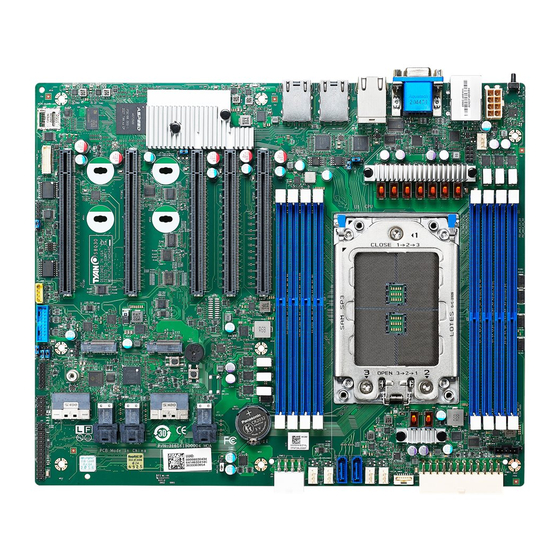
Page 12: Board Image
2.1 Board Image S8030 This picture is representative of the latest board revision available at the time of publishing. The board you receive may not look exactly like the above picture. http://www.tyan.com... -
Page 13: Block Diagram
2.2 Block Diagram S8030 Block Diagram http://www.tyan.com... -
Page 14: Mainboard Mechanical Drawing
2.3 Mainboard Mechanical Drawing http://www.tyan.com... -
Page 15: Board Parts, Jumpers And Connectors
The board you receive may not look exactly like the above diagram. But for the DIMM number please refer to the above placement for memory installation. For the latest board revision, please visit our web site at http://www.tyan.com. http://www.tyan.com... - Page 16 Reset Select (J41) ID Button Switch (J101) BMC Bypass Select (J43) BMC COM Select (J56) FPGA JTAG Select (J39) COM Port Select (J15) Jumper Legend OPEN - Jumper OFF Without jumper cover CLOSED - Jumper ON With jumper cover http://www.tyan.com...
- Page 17 J38: Front Panel Pin Header Signal Signal FP_PW_LED_PW FP_CONN_PWR FP_ID_LED_PW FP_PW_LED_GND FP_ID_LED_L HDD_LED_PW BMC_HW_FAULT_L HDD_ACT_LED_L BMC_SYS_FAULT_L FP_PWR_BTN_L LAN0_LED_P LAN0_LED_L FP_RST_BTN_JP_L FP_SMB_DAT FP_SMB_CLK FP_IDLED_BTN_L FP_INTRUSION_L SYS_AIR_INLET LAN1_LED_P FP_NMI_BTN_L LAN1_LED_L J61: PSMI Connector Signal PSMI_SMBCLK PSMI_SMBDATA PSMI_PMBUS_ALERT_L PSMI_VDD http://www.tyan.com...
- Page 18 Signal Signal VDD_5_USB_REAR P0_USB_0_SS_0RX_ESD_L VDD_5_USB_REAR P0_USB_0_SS_0RX_ESD_H P0_USB_0_SS_1RX_ESD_L P0_USB_0_SS_1RX_ESD_H P0_USB_0_SS_0TX_ESD_L P0_USB_0_SS_0TX_ESD_H P0_USB_0_SS_1TX_ESD_L P0_USB_0_SS_1TX_ESD_H USB2_HUB_ESD_DN1 USB2_HUB_ESD_DP1 USB2_HUB_ESD_DN2 P0_USB3_FRONT_OC_R_N USB2_HUB_ESD_DP2 J14/J22: 7-pin Vertical SATA Connector PIN Define SGND0 Connects to the Serial ATA ready drives via SGND1 the Serial ATA cable. SGND2 http://www.tyan.com...
- Page 19 NVME[0]/[2]_RX_N2 A15 B15 NVME[0]/[2]_TX_N2 A16 B16 NVME[0]/[2]_RX_P3 A17 B17 NVME[0]/[2]_TX_P3 NVME[0]/[2]_RX_N3 A18 B18 NVME[0]/[2]_TX_N3 A19 B19 NVME[1]/[3]_RX_P0 A20 B20 NVME[1]/[3]_TX_P0 NVME[1]/[3]_RX_N0 A21 B21 NVME[1]/[3]_TX_N0 A22 B22 NVME[1]/[3]_RX_P1 A23 B23 NVME[1]/[3]_TX_P1 NVME[1]/[3]_RX_N1 A24 B24 NVME[1]/[3]_TX_N1 A25 B25 A26 B26 NVME[1]/[3]_SCL http://www.tyan.com...
- Page 20 J25/J26/J27: Mini SAS HD Connector Signal Signal GND1 GND7 RXA0_DP TXA0_DP RXA0_DN TXA0_DN GND2 GND8 RXA1_DP TXA1_DP RXA1_DN TXA1_DN GND3 GND9 SGPIO_CLK SIDEBAND0 SGPIO_LOAD SIDEBAND1 SIDEBAND4 SGPIO_DATA_OUT SIDEBAND5 SGPIO_DATA_IN GND1 GND10 RXA2_DP TXA2_DP RXA2_DN TXA2_DN GND2 GND11 RXA3_DP TXA3_DP RXA3_DN TXA3_DN GND3 GND12 http://www.tyan.com...
- Page 21 Signal Name Signal Name SYS_FAN_T1 SYS_FAN_T6 SYS_FAN_T2 SYS_FAN_T7 SYS_FAN_T3 SYS_FAN_T8 SYS_FAN_T4 SYS_FAN_T9 SYS_FAN_T5 SYS_FAN_T10 BMC_PWM_BUF_FAN3 BMC_PWM_BUF_FAN2 SYS_FAN_T11 FAN_SDA SYS_FAN_T12 FAN_SCL VDD_33_DUAL BMC_PWM_BUF_FAN4 VDD_33_DUAL SYS_FAN_T13 SYS_FAN_T15 SYS_FAN_T14 SYS_FAN_T16 BMC_PWM_BUF_FAN5 BMC_PWM_BUF_FAN6 BMC_PWM_BUF_FAN0 J44: CPU HP SMBus Connector Signal 3.3V_Dual CPU_HP_SMBUS_CLK CPU_HP_SMBUS_DATA CPU_HP_ALERT http://www.tyan.com...
- Page 22 3.3V_RUN PERN2 3.3V_RUN PERP2 PETN2 PETP2 PERN1 12V_RUN PERP1 12V_RUN 12V_RUN PETN1 12V_RUN(Pre-Charge) PETP1 M2_DEVSLP I2C_M2_SCL(1.8V) PERN0 / SATA-B+ I2C_M2_SDA(1.8V) PERP0 / SATA-B- PETN0 / SATA-A- M2_PERST PETP0 / SATA-A+ M2_PEWAKE PE_CLK_N PE_CLK_P PRSNT1#(GND) PEDER_OC-PCIE/GND- 3.3V_RUN SATA 3.3V_RUN 3.3V_RUN http://www.tyan.com...
- Page 23 Pin 2-3 Closed: BMC Console Port1 (Default) J39: FPGA JTAG Select Jumper Pin 1-2 Closed: Switch to CONN Pin 2-3 Closed: Switch to BMC (Default) J41: Reset Select Jumper Pin 1-2 Closed: FP Reset Button=System Reset (Default) Pin 2-3 Closed: FP Reset Button=BMC Reset http://www.tyan.com...
- Page 24 J43: Bypass BMC Jumper Pin 1-2 Closed: Bypass BMC Pin 2-3 Closed: FPGA waits for BMC ready (Default) J101: ID Button Switch Pin 1-2 Closed: Press 5 seconds for BMC HW Reset Pin 2-3 Closed: Press 5 seconds for power on/off (Default) http://www.tyan.com...
-
Page 25: Led Definitions
BMC heartbeat LED inactive BMC LED for5 BMC activity BMC inactive indications. Blin king BMC work normally HDD active HDD Active LED is HDD Active LED HDD inactive only for M.2 device. Blinking http://www.tyan.com... -
Page 26: Installing The Processor And Heat Sink
Specifications on page 5. Check our website at http://www.tyan.com for latest processor support. NOTE: MITAC TYAN is not liable for damage as a result of operating an unsupported configuration. Processor Installation for AMD Socket SP3 Follow the steps below to install the processors and heat sinks. NOTE: Please save and replace the CPU protection cap when returning for service. - Page 27 Make sure to push the carrier frame with package towards the end of the rail frame until it clicks into place. Do not drop the carrier frame or touch the package pad to avoid component damage. Using your thumb and forefinger, remove the PnP cap by lifting it up vertically. http://www.tyan.com...
- Page 28 Close the force frame. Then use a T20 Torx screwdriver to tighten the screws to secure the force frame in a sequential order (123). Align and install the CPU heatsink onto the top of the CPU socket. http://www.tyan.com...
- Page 29 Connect the heatsink power cable to the mainboard connector. NOTE: Always check with the manufacturer of the heat sink & processor to ensure that the thermal interface material is compatible with the processor and meets the manufacturer’s warranty requirements. http://www.tyan.com...
-
Page 30: Tips On Installing Motherboard In Chassis
Some chassis include plastic studs instead of metal. Although the plastic studs are usable, MITAC recommends using metal studs with screws that will fasten the motherboard more securely in place. Below is a chart detailing what the most common motherboard studs look like and how they should be installed. http://www.tyan.com... - Page 31 http://www.tyan.com...
-
Page 32: Installing The Memory
Before installing memory, ensure that the memory you have is compatible with the http://www.tyan.com motherboard and processor. Check the TYAN Web site at for details of the type of memory recommended for your motherboard. This platform supports (4)+(4) DDR4 ECC RDIMM/RDIMM 3DS/LRDIMM/ LRDIMM 3DS 3200 ... - Page 33 3. Populate the same DIMM type in each channel, specifically - Use the same DIMM size - Use the same # of ranks per DIMM Memory Population Table Quantity of Memory Module Populated Single CPU Populated (CPU0) P0_UMC0_CH_A0 P0_UMC1_CH_B0 P0_UMC3_CH_C0 P0_UMC2_CH_D0 Recommended P0_UMC6_CH_E0 P0_UMC7_CH_F0 P0_UMC5_CH_G0 P0_UMC4_CH_H0 http://www.tyan.com...
- Page 34 Memory Installation Procedure Follow these instructions to install memory modules into the S8030. Unlock the clips as shown in the illustration. Insert the memory module firmly into the socket by gently pressing down until it sits flush with the socket.
-
Page 35: Attaching Drive Cables
2.9 Attaching Drive Cables Attaching Serial ATA Cables S8030 is equipped with two (2) Serial ATA (SATA) channel. Connections for the drives are very simple. There is no need to set Master/Slave jumpers on SATA drives. If you are in need of SATA/SAS cables or power adapters please contact your place of purchase. -
Page 36: Installing Add-In Cards
Doing so allows air to circulate within the chassis more easily, thus improving cooling for all installed devices. NOTE: You must always unplug the power connector to the motherboard before performing system hardware changes to avoid damaging the board or expansion device. http://www.tyan.com... -
Page 37: Connecting External Devices
Right LED No Link Link Green 10Mbps Active Blinking Green Solid Green Link Green 100Mbps Solid Green Active Blinking Green Solid Yellow Link Green 1Gbps Solid Yellow Active Blinking Green Link Green Solid Yellow 10Gbps Solid Yellow Active Blinking Green http://www.tyan.com... -
Page 38: Installing The Power Supply
2.12 Installing the Power Supply There are three (3) power connectors on your S8030 motherboard. The S8030 supports EPS 12V power supply. J60: ATX 24-pin Main Power Connector Signal Signal VDD_33_RUN VDD_33_RUN VDD_33_RUN N12V VDD_5_RUN PS_ON_L VDD_5_RUN PWRGD_PS VDD_5_STBY_PSU VDD_5_RUN... -
Page 39: Finishing Up
In the rare circumstance that you have experienced difficulty, you can find help by asking your vendor for assistance. If they are not available for assistance, please find setup information and documentation online at our website or by calling your vendor’s support line. http://www.tyan.com... - Page 40 NOTE http://www.tyan.com...
-
Page 41: Chapter 3: Bios Setup
The table below shows how to navigate in the setup program using the keyboard. Function Left/Right Arrow Keys Change from one menu to the next Up/Down Arrow Keys Move between selections Enter Open highlighted section PgUp/PgDn Keys Change pages Change options Exit http://www.tyan.com... - Page 42 The following pages provide the details of BIOS menu. Please be noticed that the BIOS menu are continually changing due to the BIOS updating. The BIOS menu provided are the most updated ones when this manual is written. Please visit TYAN’s website at http://www.tyan.com for the information of BIOS updating.
-
Page 43: Main Menu
English / Simplified Chinese / Japanese System Date Set the Date. Use Tab to switch between Date elements. Default Ranges: Year: 1998-9999 Months: 1-12 Days: dependent on month System Time Set the Time. Use Tab to switch between Time elements. http://www.tyan.com... -
Page 44: Advanced Menu
Press <Enter> to select T1s Auth Configuration. iSCSI Configuration Configure the iSCSI parameters. Network Stack Configuration Network Stack Settings. ACPI Settings System ACPI Parameters. S5 RTC Wake Settings Enable system to wake from S5 using RTC alarm. Serial Port Console Redirection Serial Port Console Redirection. http://www.tyan.com... - Page 45 SATA Configuration SATA Device Information. NVMe Configuration NVMe Device Options Settings. Trusted Computing Trusted Computing Settings. PCI Subsystem Settings PCI, PCI-X and PCI Express Settings. Option ROM Dispatch Policy Option ROM Dispatch Policy. PCIE Slot Configuration Onboard PCIE Slot Configuration http://www.tyan.com...
- Page 46 3.3.1 T1s Auth Configuration Server CA Configuration Press <Enter> to configure Server CA. Client Cert Configuration Press <Enter> to configure Client Cert. http://www.tyan.com...
- Page 47 3.3.1.1 Server CA Configuration Enroll Cert Press <Enter> to enroll cert. Delete Cert Press <Enter> to delete cert. http://www.tyan.com...
- Page 48 3.3.1.1.1 Enroll Cert Enroll Cert Using File Enroll Cert Using File. Cert GUID Input digit character in 11111111-2222-3333-4444-1234567890ab format. Commit Changes and Exit Commit Changes and Exit. Discard Changes and Exit Discard Changes and Exit. http://www.tyan.com...
- Page 49 3.3.1.2 Delete Cert FE9C6606-8849-44A3-8868-DEA3A0E0324D GUID for CERT. Disabled / Enabled http://www.tyan.com...
- Page 50 Step 3. Save changes and reboot. Attempt Priority Change the priority using +/- keys. Use arrow keys to select the attempt then press +/- to move the attempt up/down in the attempt order list. Host iSCSI Configuration Host iSCSI Configuration. http://www.tyan.com...
- Page 51 Change the priority using +/- keys. Use arrow keys to select the attempt then press +/- to move the attempt up/down in the attempt order list. Host Attempt / Redfish Attempt Commit Changes and Exit Commit Changes and Exit. http://www.tyan.com...
- Page 52 Add an attempt. Delete Attempt Delete one or more attempts. Change Attempt Order Change the priority using +/- keys. Use arrow keys to select the attempt then press +/- to move the attempt up/down in the attempt order list. http://www.tyan.com...
- Page 53 3.3.2.2.1 Add an Attempt http://www.tyan.com...
- Page 54 3.3.2.2.2 Delete Attempts Commit Changes and Exit Commit Changes and Exit. Discard Changes and Exit Discard Changes and Exit. http://www.tyan.com...
- Page 55 3.3.2.2.3 Change Attempt Order Commit Changes and Exit Commit Changes and Exit. Discard Changes and Exit Discard Changes and Exit. http://www.tyan.com...
- Page 56 Enable Ipv4 HTTP Boot Support. If disabled IPV4 HTTP boot option will not be created. Disabled / Enabled Ipv6 PXE Support Enable Ipv6 PXE Boot Support. If disabled IPV6 PXE boot option will not be created. Disabled / Enabled http://www.tyan.com...
- Page 57 Enable Ipv6 HTTP Boot Support. If disabled IPV6 HTTP boot option will not be created. Disabled / Enabled PXE boot wait time Wait time to press ESC key to abort the PXE boot. Media detect count Number of times presence of media will be checked. http://www.tyan.com...
- Page 58 3.3.4 ACPI Settings Enable ACPI Auto Configuration Enable or disable BIOS ACPI Auto Configuration. Disabled / Enabled http://www.tyan.com...
- Page 59 Select 0-23. For example enter 3 for 3am and 15 for 3pm. Wake up minute Select 0-59 for Minute. Wake up second Select 0-59 for Second. When Wake system from S5 is set to [Dynamic Time] Wake up Minute increase 1-5. http://www.tyan.com...
- Page 60 Console redirection enable or disable. Disabled / Enabled Legacy Console Redirection Settings Legacy Console redirection settings. Console Redirection Settings The settings specify how the host computer (which the user is using) will exchange data. Both computers should have the same or compatible settings. http://www.tyan.com...
- Page 61 1’s in the data bits is odd. Mark: parity bit is always 1. Space: parity bit is always 0. Mark and Space parity do not allow for error detection. None / Even / Odd / Mark / Space http://www.tyan.com...
- Page 62 On this mode enabled only text will be sent. This is to capture Terminal data. Disabled / Enabled Resolution 100x31 Enable or disable extended terminal resolution. Disabled / Enabled Putty KeyPad Select FunctionKey and KeyPad on Putty. VT100 / LINUX / XTERMR6 / SCO / ESCN / VT400 http://www.tyan.com...
- Page 63 When BootLoader is selected, then Legacy Console Redirection is disabled before booting to legacy OS, When Always Enable is selected, then Legacy Console Redirection is enabled for legacy OS. Default setting for this option is set to Always Enable. Always Enabled / BootLoader http://www.tyan.com...
- Page 64 VT-UTF8 / VT100 / VT100Plus / ANSI Bits per Second Select serial port transmission speed. The speed must be matched on the other side. Long or noisy lines may require lower speeds. 115200 / 9600 / 19200 / 57600 http://www.tyan.com...
- Page 65 ‘start’ signal can be sent to restart the flow. Hardware flow control uses two wires to send start/stop signal. None / Hardware RTS/CTS / Software Xon/Xoff Data Bits / Parity / Stop Bits Read only. http://www.tyan.com...
- Page 66 USB Mass Storage Driver Support Enable/Disable USB Mass Storage Driver Support. Enabled / Disabled Port 60/64 Emulation Enables I/O Port 60h/64h emulation support. This should be enabled for the complete USB keyboard legacy support for non-USB aware OSes. Enabled / Disabled http://www.tyan.com...
- Page 67 Controller. AUTO uses default value: for a Root port it is 100 ms, for a Hub port the delay is taken from Hub descriptor. Auto / Manual NOTE: The following item will appear when Device power-up delay is set to [Manual]. Device power-up delay in seconds Delay range is 1…40 seconds, in one second increments. http://www.tyan.com...
- Page 68 Active Video Select between onboard or external VGA support. Onboard / External LAN1~LAN4 LAN Enable/Disable control function. Enabled / Disabled NMI Button Enable or Disable NMI button. Enabled / Disabled Clock Spread Spectrum Enable/Disable Clock Spread Spectrum. Enabled / Disabled http://www.tyan.com...
- Page 69 3.3.9 AST2500 Super IO Configuration Super IO Chip Read only. Serial Port 1 Configuration Set Parameters of Serial Port 1 (COMA). http://www.tyan.com...
- Page 70 / IO=3F8h, IRQ=3, 4, 5, 6, 7, 9, 10, 11, 12; / IO=2F8h; IRQ=3, 4, 5, 6, 7, 9, 10, 11, 12; / IO=3E8h, IRQ=3, 4, 5, 6, 7, 9, 10, 11, 12; / IO=2E8h, IRQ=3, 4, 5, 6, 7, 9, 10, 11, 12; http://www.tyan.com...
- Page 71 PWM Minimal Duty Cycle (%). NOTE: This item is available when Fan Speed Control is set to [Manual]. BMC Alert Beep Enable/Disable BMC Alert Beep. On / Off PMBus support PSU Status Monitor support or not. Disabled / Enabled http://www.tyan.com...
- Page 72 3.3.10.1 Sensor Data Register Monitoring NOTE: SDR can not be modified. Read only. http://www.tyan.com...
- Page 73 Network Controls the execution of UEFI and Legacy PXE OpROM UEFI / Legacy Storage Controls the execution of UEFI and Legacy Storage OpROM UEFI / Legacy Video Controls the execution of UEFI and Legacy Video OpROM UEFI / Legacy http://www.tyan.com...
- Page 74 Other PCI devices Determines OpRom execution policy for devices other than network, storage, or video UEFI / Legacy http://www.tyan.com...
- Page 75 3.3.12 CPU Configuration SVM Mode Enable/disable CPU Virtualization. Disabled / Enabled SMEE Control secure memory encryption enable. Disabled / Enabled CPU 0 Information View Information related to CPU 0. http://www.tyan.com...
- Page 76 3.3.12.1 CPU 0 Information Read only. http://www.tyan.com...
- Page 77 3.3.13 SATA Configuration Read only. http://www.tyan.com...
- Page 78 3.3.14 NVMe Configuration Read only. http://www.tyan.com...
- Page 79 3.3.15 Trusted Computing Security Device Support Enables or Disables BIOS support for security device. O.S. will not show Security Device. TCG EFI protocol and INT1A interface will not be available. Enabled / Disabled http://www.tyan.com...
- Page 80 Enables or Disables 64bit capable Devices to be Decoded in Above 4G Address Space (Only if System Supports 64 bit PCI Decoding). Enabled / Disabled SR-IOV Support If system has SR-IOV capable PCIe Devices, this option Enables or Disables Single Root IO Virtualization Support. Enabled / Disabled http://www.tyan.com...
- Page 81 3.3.16.1 PCI Express Settings Maximum Payload Set Maximum Payload of PCI Express Device or allow System BIOS to select the value. Auto / 128 Bytes / 256 Bytes / 512 Bytes / 1024 Bytes / 2048 Bytes / 4096 Bytes http://www.tyan.com...
- Page 82 Enable or Disable LAN2 Option ROM. Enabled / Disabled LAN3 Enable or Disable LAN3 Option ROM. Enabled / Disabled LAN4 Enable or Disable LAN4 Option ROM. Enabled / Disabled PCIE#1~5 Enable or Disable Option ROM execution for selected Slot. Enabled / Disabled http://www.tyan.com...
- Page 83 PCIe Slot Bifurcation Configuration PCIE#1~PCIE#5 Selects PCIe port Bifurcation for PCIE#1~PCIE#5 slot. x16 / x8x8 / x4x4x4x4 PCIe Slot Link Speed Configuration PCIE#1~PCIE#5 Maximum Link Speed for PCIE#1~PCIE#5 slot. Auto / Gen1 (2.5GT/s) / Gen2 (5GT/s) / Gen3 (8GT/s) / Gen4 (16GT/s) http://www.tyan.com...
-
Page 84: Chipset Menu
3.4 Chipset Menu PCIe Compliance Mode PCIe Link Compliance Mode. Disabled / Enabled North Bridge North Bridge Parameters http://www.tyan.com... - Page 85 3.4.1 North Bridge Configuration Socket 0 Configuration View Information related to Socket 0. http://www.tyan.com...
- Page 86 3.4.1.1 Socket 0 Information Read only. http://www.tyan.com...
-
Page 87: Amd Cbs
3.5 AMD CBS CPU Common Options CPU Common Options. DF Common Options DF Common Options. UMC Common Options UMC Common Options. NBIO Common Options NBIO Common Options. FCH Common Options FCH Common Options. http://www.tyan.com... - Page 88 Enable/disable PFEH, cloak individual banks, and mask deferred error interrupts from each bank. Enabled / Disabled / Auto Core Performance Boost Disable CPB. Disabled / Auto Global C-state Control Controls IO based C-state generation and DF C-states. Disabled / Enabled / Auto http://www.tyan.com...
- Page 89 SEV-ES ASIDs. Hence, the valid values for this field is 1 --- (SEV ASID Count +1) Local APIC Mode Local APIC Mode. xAPIC / x2APIC / Auto MCA error thresh count Default is 10, and the threshold range is from 1 to 4095. http://www.tyan.com...
- Page 90 POWER CYCLE is required in order for future selections to take effect. TWO (1+1) / FOUR (2+2) / SIX (3+3) / Auto SMT control Can be used to disable symmetric multithreading. To re-enable SMT, a POWER CYCLE is needed after selecting the ‘Auto’ option. Disabled / Auto http://www.tyan.com...
- Page 91 3.5.1.2 Prefetcher Settings L1 Stream HW Prefetcher Option to Enable / Disable L1 Stream HW Prefetcher. Enabled / Disabled / Auto L2 Stream HW Prefetcher Option to Enable / Disable L2 Stream HW Prefetcher. Enabled / Disabled / Auto http://www.tyan.com...
- Page 92 3.5.2 DF Common Options Scrubber Scrubber. Memory Addressing Memory Addressing. ACPI ACPI. http://www.tyan.com...
- Page 93 Provide a value that is the number of hours to scrub memory. Disabled / 1 hour / 4 hours / 8 hours / 16 hours / 24 hours / 48 hours / Auto Redirect scrubber control Redirect scrubber control. Disabled / Enabled / Auto http://www.tyan.com...
- Page 94 Controls the memory interleaving size. The valid value are AUTO, 256 bytes, 512 bytes, 1 Kbytes or 2Kbytes. This determines the starting address of the interleave (bit 8, 9, 10 or 11). 256 Bytes / 512 Bytes / 1 KB / 2 KB / Auto http://www.tyan.com...
- Page 95 3.5.2.3 ACPI ACPI SRAT L3 Cache As NUMA Domain Enabled: Each CCX in the system will be declared as a separate NUMA domain. Disabled: Memory Addressing \ NUMA nodes per socket will be declared. Disabled / Enabled / Auto http://www.tyan.com...
- Page 96 3.5.3 UMC Common Options DDR4 Common Options DDR4 Common Options. DRAM Memory Mapping DRAM Memory Mapping. NVDIMM NVDIMM. http://www.tyan.com...
- Page 97 3.5.3.1 DDR4 Common Options DRAM Timing Configuration DRAM Timing Configuration. Common RAS Common RAS. Security Security. http://www.tyan.com...
- Page 98 3.5.3.1.1 DRAM Timing Configuration Overclock Memory Overclock Settings. Enabled / Auto NOTE: The following item is available when Overclock is set to [Enabled]. Memory Clock Speed Specifies the memory clock frequency. 2666MT/s / 2933MT/s / 3200MT/s / Auto http://www.tyan.com...
- Page 99 3.5.3.1.2 Common RAS Data Poisoning Enable/disable data poisoning: Enabled / Disabled / Auto ECC Configuration ECC Configuration. http://www.tyan.com...
- Page 100 3.5.3.1.2.1 ECC Configuration DRAM ECC Symbol Size DRAM ECC Symbol Size (x4/x8/x16). x4 / x8 / x16 / Auto DRAM ECC Enable Use this option to enable/disable DRAM ECC. Auto will set ECC to enable. Enabled / Disabled / Auto http://www.tyan.com...
- Page 101 3.5.3.1.3 Security TSME Transparent Secure Memory Encryption. Enabled / Disabled / Auto Data Scramble Data scrambling. Enabled / Disabled / Auto http://www.tyan.com...
- Page 102 3.5.3.2 DRAM Memory Mapping Chipselect Interleaving Interleave memory blocks across the DRAM chip selects for node 0. Disabled / Auto BankGroupSwap Bank Group Swap settings. Enabled / Disabled / Auto http://www.tyan.com...
- Page 103 3.5.3.3 NVDIMM NVDIMM-N Feature Disable NVDIMM-N feature for memory margin tool. Disabled / Enabled http://www.tyan.com...
- Page 104 PCIe ARI Support Enables Alternative Routing-ID Interpretation. Enabled / Disabled / Auto Preferred IO Preferred IO Select Type. Manual: Bus Number manually Auto: Default Manual / Auto NOTE: The following item is available when Preferred IO is set to [Manual]. http://www.tyan.com...
- Page 105 Preferred IO Bus Preferred IO Bus Number 0x0-0xFF: Bus Number SMU Common Options SMU Common Options. http://www.tyan.com...
- Page 106 Auto = Use default performance determinism settings Power Performance Auto / Power / Performance cTDP Control Auto = Use the fused TDP Manual = User can set customized TDP Manual / Auto NOTE: cTDP is available when cTDP Control is set to [Manual]. http://www.tyan.com...
- Page 107 Enable or Disable Data Fabric to go to a low-power state when the processor has entered Cx states. Power Performance Disabled / Enabled / Auto Fixed SOC Pstate Fixed SOC Pstate. P0 / P1 / P2 / P3 / Auto http://www.tyan.com...
- Page 108 3.5.5 FCH Common Options AC Power Loss Options AC Power Loss Options. http://www.tyan.com...
- Page 109 3.5.4.1 AC Power Loss Options Restore AC Power Loss Select Restore AC Power Loss Method. Power Off / Power On / Last State http://www.tyan.com...
-
Page 110: Server Management
Do Nothing / Reset / Power Down / Power Cycle OS Watchdog Timer If enabled, starts a BIOS timer which can only be shut off by Management Software after the OS loads. Helps determine that the OS successfully loaded or follows the OS Boot Watchdog Timer policy. http://www.tyan.com... - Page 111 Enable or Disable BMC Logo. Enabled / Disabled System Event Log Press <Enter> to change the SEL event log configuration. BMC network configuration Configure BMC network parameters. BMC User Settings Press <Enter> to Add, Delete and Set Privilege level for users. http://www.tyan.com...
- Page 112 Do Nothing / Erase Immediately / Delete Oldest Record Log EFI Status Codes Disable the logging of EFI Status Codes or log only error code or only progress code or both. Disabled / Both / Error Code / Progress Code http://www.tyan.com...
- Page 113 BMC). Unspecified option will not modify any BMC network parameters during BIOS phase. Unspecified / Static / DynamicBmcDhcp / DynamicBmcNonDhcp Management Port 2 Enable/Disable BMC Share NIC. Enabled / Disabled Configure IPV6 support Management Port 1 IPV6 Support Enable or Disable LAN1 IPV6 Support. Enabled / Disabled http://www.tyan.com...
- Page 114 Select the configure LAN channel parameters statically or dynamically (by BIOS or BMC). Unspecified option will not modify any BMC network parameters during BIOS phase. Unspecified / Static / DynamicBmcDhcp Management Port 2 IPV6 Support Enable or Disable LAN2 IPV6 Support. Enabled / Disabled http://www.tyan.com...
- Page 115 3.6.3 BMC User Settings Add User Press <Enter> to Add a user. Delete User Press <Enter> to Delete a user. Change User Settings Press <Enter> to change User Settings. http://www.tyan.com...
- Page 116 Enabled / Disabled Channel No Enter BMC Channel Number. 1 – Dedicated LAN 8 – Shared LAN N/A / 1 / 8 User Privilege Limit Enter BMC User Privilege Limit for Selected Channel. None / User / Operator / Administrator http://www.tyan.com...
- Page 117 3.6.3.2 Delete User User Name Enter BMC User Name. Change User Password Enter New Password to change. Password at least 8 characters. http://www.tyan.com...
- Page 118 Enabled / Disabled Channel No Enter BMC Channel Number. 1 – Dedicated LAN 8 – Shared LAN N/A / 1 / 8 User Privilege Limit Enter BMC User Privilege Limit for Selected Channel. None / User / Operator / Administrator http://www.tyan.com...
-
Page 119: Security
Set user password in the Create New Password window. After you key in the password, the Confirm New Password window will pop out to ask for confirmation. Secure Frozen Mode Disable means Hard Drive on Non-frozen mode. Enable means Hard Drive on Frozen mode. Enabled / Disabled Secure Boot Secure Boot Configuration. http://www.tyan.com... - Page 120 Delete all Secure Boot key database from NVRAM. Deleting all variables will reset the System to Setup Mode. Press ‘Yes’ to proceed ‘No’ to cancel. Key Management Enables expert users to modify Secure Boot Policy variables without full authentication. http://www.tyan.com...
- Page 121 Delete all Secure Boot key database from NVRAM. Deleting all variables will reset the System to Setup Mode. Press ‘Yes’ to proceed ‘No’ to cancel. Export Secure Boot variables Copy NVRAM content of Secure Boot variables to files in a root folder on a file system device. http://www.tyan.com...
- Page 122 Authorized Signatures Enroll Factory Defaults or load certificates from a file: 1. Public Key Certificate in: a) EFI_SIGNATURE_LIST b) EFI_CERT_X509 (DER) c) EFI_CERT_RSA2048 (bin) d) EFI_CERT_SHAXXX 2. Authenticated UEFI Variable 3. EFI PE/C0FF Image (SHA256) Key source: Factory, External, Mixed http://www.tyan.com...
- Page 123 Enroll Factory Defaults or load certificates from a file: 1. Public Key Certificate in: a) EFI_SIGNATURE_LIST b) EFI_CERT_X509 (DER) c) EFI_CERT_RSA2048 (bin) d) EFI_CERT_SHAXXX 2. Authenticated UEFI Variable 3. EFI PE/C0FF Image (SHA256) Key source: Factory, External, Mixed Update / Append http://www.tyan.com...
-
Page 124: Boot
Bootup NumLock State Select the keyboard NumLock state. Off / On Quiet Boot Enable or disable Quiet Boot option. Enabled / Disabled Wait for ‘ESC’ If Error Wait for ‘ESC’ key to be pressed if error occurs. Enabled / Disabled http://www.tyan.com... - Page 125 Endless Boot Enable or disable Endless Boot. Enabled / Disabled Boot Option Priorities Boot Option #1 Select the first/second boot device. Device Name / Disabled Delete Boot Option Remove an EFI boot option from the boot order. http://www.tyan.com...
- Page 126 3.8.1 Delete Boot Option Delete Boot Option Remove an EFI boot option from the boot order. Select one to Delete / UEFI: Built-in EFI Shell http://www.tyan.com...
-
Page 127: Save & Exit
Reset the system after saving the changes. Discard Changes and Reset Reset system setup without saving any changes. Save Changes Save changes done so far to any of the setup options. Discard Changes Discard changes done so far to any of the setup options. http://www.tyan.com... - Page 128 Restore Defaults Restore/Load Default values for all the setup options. Save as User Defaults Save the changes done so far as User Defaults. Restore User Defaults Restore the User Defaults to all the setup options. Boot Override Read only. http://www.tyan.com...
-
Page 129: Chapter 4: Diagnostics
BIOS flash failure, you must contact your dealer for a replacement BIOS. There are no exceptions. TYAN does not have a policy for replacing BIOS chips directly with end users. In no event will TYAN be held responsible for damages done by the end user. -
Page 130: Amibios Post Code (Aptio)
South Bridge initialization before microcode loading 0x05 OEM initialization before microcode loading 0x06 Microcode loading 0x07 AP initialization after microcode loading 0x08 North Bridge initialization after microcode loading 0x09 South Bridge initialization after microcode loading 0x0A OEM initialization after microcode loading 0x0B Cache initialization http://www.tyan.com... - Page 131 CPU post-memory initialization is started 0x33 CPU post-memory initialization. Cache initialization 0x34 CPU post-memory initialization. Application Processor(s) (AP) initialization 0x35 CPU post-memory initialization. Boot Strap Processor (BSP) selection 0x36 CPU post-memory initialization. System Management Mode(SMM) initialization 0x37 Post-Memory North Bridge initialization is started http://www.tyan.com...
- Page 132 Reserved for future AMI progress codes S3 Resume Error Codes 0xE8 S3 Resume Failed 0xE9 S3 Resume PPI not Found 0xEA S3 Resume Boot Script Error 0xEB S3 OS Wake Error 0xEC – 0xEF Reserved for future AMI error codes http://www.tyan.com...
- Page 133 South Bridge DXE SMM initialization is started 0x72 South Bridge devices initialization 0x73 South Bridge DXE initialization (South Bridge module specific) 0x74 South Bridge DXE initialization (South Bridge module specific) 0x75 South Bridge DXE initialization (South Bridge module specific) http://www.tyan.com...
- Page 134 Setup Verifying Password 0xA9 Start of Setup 0xAA Reserved for ASL (see ASL Status Codes section below) 0xAB Setup Input Wait 0xAC Reserved for ASL (see ASL Status Codes section below) 0xAD Ready To Boot event 0xAE Legacy Boot event http://www.tyan.com...
- Page 135 System is entering S4 sleep state 0x05 System is entering S5 sleep state 0x10 System is waking up from the S1 sleep state 0x20 System is waking up from the S2 sleep state 0x30 System is waking up from the S3 sleep state http://www.tyan.com...
- Page 136 Status Code Description 0x40 System is waking up from the S4 sleep state 0xAC System has transitioned into ACPI mode. Interrupt controller is in PIC mode. 0xAA System has transitioned into ACPI mode. Interrupt controller is in APIC mode. http://www.tyan.com...
-
Page 137: Appendix I: Fan And Temp Sensors
The red spot indicates the sensor. Fan and Temp Sensor Location: Fan Sensor: It is located in the third pin of the fan connector, which detects the fan speed (rpm) Temp Sensor: refer to Figure 1: Sensor Location. They detect the system temperature around. http://www.tyan.com... - Page 138 BIOS Temp Sensor Name Explanation: http://www.tyan.com...
- Page 139 Temperature of CPU0 DIMM Channel G P0_UMC4_CH_H Temperature of CPU0 DIMM Channel H CPU_FAN Fan Speed of CPU_FAN SYS_FAN_1 Fan Speed of SYS_FAN_1 SYS_FAN_2 Fan Speed of SYS_FAN_2 SYS_FAN_3 Fan Speed of SYS_FAN_3 SYS_FAN_4 Fan Speed of SYS_FAN_4 SYS_FAN_5 Fan Speed of SYS_FAN_5 http://www.tyan.com...
- Page 140 Fan Speed of SYS_FAN_10 SYS_FAN_11 Fan Speed of SYS_FAN_11 SYS_FAN_12 Fan Speed of SYS_FAN_12 PSU0_STATUS Current status of PSU0 PSU0_Temp Temperature of PSU0 PSU0_FAN Fan Speed of PSU0 PSU1_STATUS Current status of PSU1 PSU1_Temp Temperature of PSU1 PSU1_FAN Fan Speed of PSU1 http://www.tyan.com...
-
Page 141: Appendix Ii: M.2 Latch Installation
This section provides a step-by-step demonstration on how to install a M.2 latch. 1. Take out the M.2 latch packs from the Accessory Box. 2. Insert the M.2 latch into the hole and then turn 90 degrees to the left as shown below. http://www.tyan.com... - Page 142 NOTE: The arrow sign on the blue knob is now turned left. 3. Push the blue knob slightly to the left as the arrow shows to lock the M.2 card in place. http://www.tyan.com...
- Page 143 4. The installation of the M.2 latch is now complete. http://www.tyan.com...
- Page 144 NOTE http://www.tyan.com...
-
Page 145: Glossary
(reading to or writing from a disk drive a single time is much faster than doing so repeatedly) there is the possibility of losing your data should the system crash. Information in a buffer is temporarily stored, not permanently saved. http://www.tyan.com... - Page 146 (like soundcards or keyboards) to access the main memory without involving the CPU. This frees up CPU resources for other tasks. As with IRQs, it is vital that you do not double up devices on a single line. Plug-n-Play devices will take care of this for you. http://www.tyan.com...
- Page 147 EEPROM (Electrically Erasable Programmable ROM): also called Flash BIOS, it is a ROM chip which can, unlike normal ROM, be updated. This allows you to keep ® up with changes in the BIOS programs without having to buy a new chip. TYAN ’s BIOS updates can be found at http://www.tyan.com...
- Page 148 PXE (Preboot Execution Environment): one of four components that together make up the Wired for Management 2.0 baseline specification. PXE was designed to define a standard set of preboot protocol services within a client with the goal of allowing networked-based booting to boot using industry standard protocols. http://www.tyan.com...
- Page 149 NVIDIA s (graphics communications processing units) and NVIDIA MCPs (media and processors). application Depending on the , NVIDIA SLI can deliver as much as two times the performance of a single GPU configuration. http://www.tyan.com...
- Page 150 CPUs without damaging the sensitive CPU pins. The CPU is lightly placed in an open ZIF socket, and a lever is pulled down. This shifts the processor over and down, guiding it into the board and locking it into place. http://www.tyan.com...
-
Page 151: Technical Support
(which can have expensive consequences). If these options are not available for you then TYAN can help. Besides designing innovative and quality products for over a decade, TYAN has continuously offered customers service beyond their expectations. - Page 152 (RMA) number. The RMA number Should be prominently displayed on the outside of the shipping carton and the package should be mailed prepaid. TYAN will pay to have the board shipped back to you. Notice for the USA Compliance Information Statement (Declaration of...
Need help?
Do you have a question about the S8030 and is the answer not in the manual?
Questions and answers