Table of Contents
Advertisement
S8253
Version 1.0a
Copyright
Copyright © 2020 MiTAC International Corporation. All rights reserved. No part of
this manual may be reproduced or translated without prior written consent from
MiTAC International Corporation.
Trademark
All registered and unregistered trademarks and company names contained in this
manual are property of their respective owners including, but not limited to the
following.
®
TYAN
is a trademark of MiTAC International Corporation.
®
®
AMD
is a trademark of AMD
Corporation.
AMI, AMI BIOS are trademarks of AMI Technologies.
®
®
Microsoft
, Windows
are trademarks of Microsoft Corporation.
®
Winbond
is a trademark of Winbond Electronics Corporation.
Notice
Information contained in this document is furnished by MiTAC International
Corporation and has been reviewed for accuracy and reliability prior to printing.
MiTAC assumes no liability whatsoever, and disclaims any express or implied
®
warranty, relating to sale and/or use of TYAN
products including liability or
warranties relating to fitness for a particular purpose or merchantability. MiTAC
retains the right to make changes to product descriptions and/or specifications at
any time, without notice. In no event will MiTAC be held liable for any direct or
indirect, incidental or consequential damage, loss of use, loss of data or other
malady resulting from errors or inaccuracies of information contained in this
document.
1
http://www.tyan.com
Advertisement
Table of Contents

Subscribe to Our Youtube Channel
Related Manuals for TYAN S8253


Summary of Contents for TYAN S8253
-
Page 1: S8253
Corporation and has been reviewed for accuracy and reliability prior to printing. MiTAC assumes no liability whatsoever, and disclaims any express or implied ® warranty, relating to sale and/or use of TYAN products including liability or warranties relating to fitness for a particular purpose or merchantability. MiTAC retains the right to make changes to product descriptions and/or specifications at any time, without notice. -
Page 2: Table Of Contents
Contents S8253 ......................1 Before you begin… ..................3 Chapter 1: Instruction ................4 1.1 Congratulations ................. 4 1.2 Hardware Specifications ..............4 1.3 Software Specifications ..............9 Chapter 2: Board Installation ..............10 2.1 Board Image ..................11 2.2 Block Diagram ................. 12 2.3 Motherboard Mechanical Drawing ........... -
Page 3: Before You Begin
S8253 Motherboard x 1 SATA Single Cable x 2 Rear IO shielding x 1 S8253 Quick Installation Guide x 1 IMPORTANT NOTE: Sales samples may not come with any of the accessories listed above. If you have ordered a sales sample and you are missing any of the above items, please contact your sales representative to help order accessories. -
Page 4: Chapter 1: Instruction
S8253 is capable of offering scalable 32 and 64-bit computing, high-bandwidth memory design, and lightning-fast PCI-E bus implementation. The S8253 not only empowers you in today’s demanding IT environment but also offers a smooth path for future application upgradeability. All of these rich feature sets provide the S8253 with the power and flexibility to meet demanding requirements for today’s IT environments. - Page 5 2x12 Power input connectors Please refer to our TPM supported TPM (Optional) TPM Support list. Chipset Aspeed AST2500 Total (6) 4-pin headers System Monitoring Monitors temperature for CPU & Temperature memory & system environment Voltage Monitors voltage for CPU, memory, http://www.tyan.com...
- Page 6 Operating System OS supported list lists. Motherboard (1) S8253 Motherboard Manual (1) Quick Installation Guide Package Contains Cable (2) SATA signal cables Installation CD (1) TYAN Device Driver CD I/O Shield (1) I/O Shield Optional accessories Riser Card M8253T65-R32-3F http://www.tyan.com...
- Page 7 1.2V (1) PCIe Gen.4 x32 slot, (3) PCIe PCIe Gen.4 x16 slot, (1) PCIe Gen.4 x8 slot Expansion Slots Recommended TYAN M8253T65-R32-3F, 2U riser card Riser Card for slot #6.5 w/ (3) PCIe slots (PCIe Gen.4) (right) (2) 10GbE ports, (2) GbE ports,...
- Page 8 3.0/PnP/Wake on LAN, Boot from BIOS USB device/PXE via LAN/Storage, Feature Console Redirection, ACPI 6.1, ACPI sleeping states S0, S5, FAN speed control automatic Form Factor EATX Physical Dimension Board Dimension 12" x 13.4" (304.8 x 340.36mm) Regulation FCC (SDoC) Class A http://www.tyan.com...
-
Page 9: Software Specifications
(1) TYAN Device Driver CD I/O Shield (1) I/O Shield Optional accessories Riser Card M8253T65-R32-3F 1.3 Software Specifications For the latest AST2500 User’s Guide and OS (operation system) support, please visit the Tyan’s Web site at http://www.tyan.com for the latest information http://www.tyan.com... -
Page 10: Chapter 2: Board Installation
Caution! To avoid damaging the motherboard and associated components, do not use torque force greater than 5~7kgf/cm (4.35~6.09 lb/in) on each mounting screw for motherboard installation. Do not apply power to the board if it has been damaged. http://www.tyan.com... -
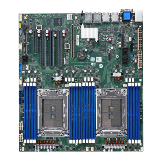
Page 11: Board Image
2.1 Board Image S8253GM4NE-2T This picture is representative of the latest board revision available at the time of publishing. The board you receive may not look exactly like the above picture. http://www.tyan.com... -
Page 12: Block Diagram
2.2 Block Diagram S8253 Block Diagram http://www.tyan.com... -
Page 13: Motherboard Mechanical Drawing
2.3 Motherboard Mechanical Drawing http://www.tyan.com... -
Page 14: Board Parts, Jumpers And Connectors
The board you receive may not look exactly like the above diagram. The DIMM slot numbers shown above can be used as a reference when reviewing the DIMM population guidelines shown later in the manual. For the latest board revision, please visit our web site at http://www.tyan.com. http://www.tyan.com... - Page 15 15. PWR3 (J62) 36. Micro SD Card Connector (J19) 16. SYS_FAN_4 (J180) 37. FPGA JTAG Connector (J59) 17. SYS_FAN_3 (J404) 38. TYAN Module Header (J40) 18. SYS_FAN_2 (J45) 39. RESET Button (SW2) 19. SYS_FAN_1 (J44) 40. POWER Button (SW4) 20. CPU0_FAN (J18) 41.
- Page 16 BMC_TACH_SYS_FAN9 BMC_TACH_SYS_FAN5 BMC_TACH_SYS_FAN10 BMC_TACH_SYS_FAN6 BMC_TACH_SYS_FAN11 BMC_PWM_BUF_FAN3 BMC_PWM_BUF_FAN2 BMC_TACH_SYS_FAN12 BMC_SDA3 BMC_TACH_SYS_FAN13 BMC_SCL3 3.3V BMC_PWM_BUF_FAN4 3.3V BMC_TACH_SYS_FAN14 BMC_TACH_SYS_FAN1 BMC_TACH_SYS_FAN15 BMC_TACH_SYS_FAN0 BMC_PWM_BUF_FAN5 BMC_PWM_BUF_FAN6 BMC_PWM_BUF_FAN0 J67: IPMB Connector Signal Signal IPMB_CLK IPMB_DATA J37: HDT Header Signal Signal P1V8_AUX TRST_N PEROK RESET_N DBREQ_N P1V8_AUX http://www.tyan.com...
- Page 17 Use this header to connect the cooling fan to your motherboard to keep the system stable and reliable. Note: A 4-pin fan is required for fan support 4pin Control J20: CPU1_FAN J18: CPU0_FAN J44: SYS_FAN_1 J45: SYS_FAN_2 J180: SYS_FAN_4 J404: SYS_FAN_3 http://www.tyan.com...
- Page 18 HDD_LED- FAULT_LED2- PWR_SW# LAN1 ACTLED+ LAN1 ACTLED- RST_SW# SMBus SDA SMBus SCL SYS_ID_SW# INTRUSION# TEMP SENSOR LAN2 ACTLED+ NMI_SW# LAN2 ACTLED- DBG_HD1: TYAN Module Header Signal Signal VDD_33_RUN FRAME_N LAD0 LAD1 RESET# LAD2 LAD3 DBG_SERIRQ DBG_PRES_N 3VSB TPM_PP_EN J61: PSMI Connector...
- Page 19 NVME[1,3,5,7]_RX_P2 NVME[1,3,5,7]_TX_P2 NVME[1,3,5,7]_RX_N2 NVME[1,3,5,7]_TX_N2 CPU_NVME_SCL CPU_NVME_SDA NVME_CLK_DP NVME_PERST_N NVME_CLK_DN NVME_HP_ALERT_N NVME[1,3,5,7]_RX_P1 NVME[1,3,5,7]_TX_P1 NVME[1,3,5,7]_RX_N1 NVME[1,3,5,7]_TX_N1 NVME[1,3,5,7]_RX_P0 NVME[1,3,5,7]_TX_P0 NVME[1,3,5,7]_RX_N0 NVME[1,3,5,7]_TX_N0 NVME[0,2,4,6]_RX_P3 NVME[0,2,4,6]_TX_P3 NVME[0,2,4,6]_RX_N3 NVME[0,2,4,6]_TX_N3 NVME[0,2,4,6]_RX_P2 NVME[0,2,4,6]_TX_P2 NVME[0,2,4,6]_RX_N2 NVME[0,2,4,6]_TX_N2 BMC_SMBus_SCL SMB_SW_BIT0 BMC_SMBus_SDA SMB_SW_BIT1 PERST_N NVME[0,2,4,6]_RX_P1 NVME[0,2,4,6]_TX_P1 NVME[0,2,4,6]_RX_N1 NVME[0,2,4,6]_TX_N1 NVME[0,2,4,6]_RX_P0 NVME[0,2,4,6]_TX_P0 NVME[0,2,4,6]_RX_N0 NVME[0,2,4,6]_TX_N0 http://www.tyan.com...
- Page 20 SIDEBAND4 SIDEBAND5 TXA1_DP TXA0_DP TXA1_DN TXA0_DN TXA3_DP TXA2_DP TXA3_DN TXA2_DN J46: Rear IO ID LED Button Signal Signal FP_IDLED_BTN_N SW4: POWER Button Signal PWR_BTN1 PWR_BTN1 SW2: COLD Reset Button Signal FP_RST_BTN_N FP_RST_BTN_N SW3: NMI Button Signal FP_NMI_BTN_N NMI_BTN_L 52 http://www.tyan.com...
- Page 21 Signal Signal COLD_RST_BTN_L FP_RST_BTN_JP_L BMC_EXTRST_BTN_L 1-2: FP RESET BUTTON = SYSTEM RESET <DEFAULT> 2-3: FP RESET BUTTON = BMC RESET J53: COM_SEL1 (BMC COM Select) Jumper Signal Signal AMD_COM_EN BMC_COM_EN 1-2: AMD COM PORT0 2-3: BMC CONSOLE PORT1 <DEFAULT> http://www.tyan.com...
- Page 22 3. Move the jumper cap to close Pin_2 and Pin_3 for several seconds to Clear CMOS. Clear CMOS 4. Put jumper cap back to Pin_1 and Pin_2 (Default setting). 5. Reconnect power connectors to the motherboard and power on system. http://www.tyan.com...
-
Page 23: Led Definitions
BMC controller cannot BMC_HBLED BMC Heart Beat LED be detected or properly initiated. The LED blinks per second to indicate that the Blinking Green BMC controller is working normally Signal VDD_33_DUAL REAR_ID_LED_N ID_LED2 ID_LED State Description Not ID BLUE ID_LED http://www.tyan.com... -
Page 24: Installing The Processor And Heatsink
2.6 Installing the Processor and Heatsink The types of processors supported by the S8253 are listed in the 1.2 Hardware Specifications section on page 4. Check our website at http://www.tyan.com ® the latest list of validated AMD processors for this specific motherboard. - Page 25 -) make sure to push the carrier frame with package towards the end of the rail frame until it clicks in place. -) do not drop the carrier frame or touch the package pad to avoid component damage. Using your thumbs and forefinger, remove the PnP cap by lifting it up vertically. http://www.tyan.com...
- Page 26 Carefully close the rail frame with the installed package. Then push both edges of the rail frame firmly until it locks in place. Close the force frame. Then use a T20 Torx screwdriver to tighten the screws to secure the force frame in a sequential order (1->2->3). http://www.tyan.com...
- Page 27 The following diagram illustrates how to install the heatsink on the AMD Socket: 1. Align and install the CPU heatsink onto the top of the CPU socket. 2. Tighten the four screws in a diagonal sequence to secure the heatsink. http://www.tyan.com...
-
Page 28: Thermal Interface Material
CPU lid (applying too much will actually reduce the cooling). NOTE: Always check with the manufacturer of the heat sink & processor to ensure that the thermal interface material is compatible with the processor and meets the manufacturer’s warranty requirements. http://www.tyan.com... -
Page 29: Tips On Installing Motherboard In Chassis
Be especially careful to look for extra stand-offs. If there are any stand-offs present that are not aligned with a mounting hole on the motherboard, it will likely short components on the back of the motherboard when installed. This will cause malfunction and/or damage to your motherboard. http://www.tyan.com... - Page 30 Some chassis include plastic studs instead of metal. Although the plastic studs are usable, MiTAC recommends using metal studs with screws that will fasten the motherboard more securely in place. Below is a chart detailing what the most common motherboard studs look like and how they should be installed. http://www.tyan.com...
-
Page 31: Installing The Memory
2.9 Installing the Memory Before installing memory, ensure that the memory you have is compatible with the motherboard and processor. Check the TYAN Web site at http://www.tyan.com details of the type of memory recommended for your motherboard. This platform supports (8)+(8) DDR4 slots ... - Page 32 Rome/Milan in Rome/Milan in DIMM DIMM 0 DIMM 1 legacy optimized Type platform platform 2666 3200 2133 2933 2R or 2DR 2400 3200 2R or 2DR 2133 2933 2R or 2DR 2R or 2DR 2133 2933 2666 3200 2133 2933 http://www.tyan.com...
- Page 33 Memory Installation Procedure Follow these instructions to install memory modules into the S8253. Unlock a DIMM socket by Press the retaining clip outwardly in the following illustration. Align the memory module with the socket,such that the DIMM NOTCH match the KEY SLOT on the socket.
-
Page 34: Attaching Drive Cables
The following illustrates how to make a SATA Cable connection. If you are in need of SATA/SAS cables or power adapters please contact your local sales representative. 1. SATA drive cable connection 2. SATA drive power connection 3. SATA cable motherboard connector 4. SATA drive power adapter http://www.tyan.com... -
Page 35: Installing Add-In Cards
Doing so allows air to circulate within the chassis more easily, thus improving cooling for all installed devices. NOTE: You must always unplug the power connector from the motherboard before performing system hardware changes to avoid damaging the board or expansion device. http://www.tyan.com... -
Page 36: Connecting External Devices
LAN4 LAN2 LAN3 LAN1 COM Port ID_Button USB3.1x2 Port S8253GM4NE-2T LAN2 LAN1 S8253GM2NE NOTE: S8253GM4NE-2T (1G+10G) Two x550 chipset for10G LAN port and two i210 for 1G LAN port S8253GM2NE (1G) Two i210 chipset for 1G LAN port only http://www.tyan.com... - Page 37 1GbE LAN Port 10/100/1000 Mbps LAN Link/Activity LED Scheme Left LED Right LED Link Green 10 Mbps Active Blinking Green Link Green Green 100 Mbps Active Blinking Green Green Link Green Amber 1000 Mbps(1Gbps) Active Blinking Green Amber No Link http://www.tyan.com...
-
Page 38: Installing The Power Supply
2.13 Installing the Power Supply There are Five (5) power connectors on your S8253 motherboard. The S8253 supports EPS 12V power supply. J60: ATX 24-Pin Power Connector (Current rating 13A) Signal Signal +3.3 Vdc +3.3 Vdc +3.3 Vdc -12 Vdc... -
Page 39: Chapter 3: Bios Setup
Exit current menu <F1> General help <F2> Previous values <F3> Load the Optimal default configuration values of the menu <F4> Save and exit <K> Scroll help area upwards <M> Scroll help area downwards <PgUp> / <PgDn> Move cursor to next/previous page http://www.tyan.com... - Page 40 BIOS menus are continually changing due to continual BIOS updates over the product lifespan of the motherboard. The BIOS menus provided are current as of the date when this manual was written. Please visit TYAN’s website at http://www.tyan.com for information on BIOS updates available for this specific motherboard.
-
Page 41: Main Menu
It displays BIOS related information. Product Name It displays Product information. BIOS Version It displays BIOS version information Build Date and Time It displays the time when built Memory Information It displays the total memory size. Memory Frequency It displays Memory frequency http://www.tyan.com... - Page 42 System Date Set the Date. Use Tab to switch between Date elements. Default Ranges: Year: 2005-2099 Months: 1-12 Days: dependent on month System Time Adjust the system clock. HH (24 hours format): MM (Minutes): SS (Seconds) Access Level Adminstrator http://www.tyan.com...
-
Page 43: Advanced Menu
Press<Enter> to select Tls Auth Configuration parameters iSCSI Configuration Configure the iSCSI parameters VLAN Configuration VLAN Configuration(MAC:864E627D2E8) MAC: 864E6274D2E8-IPv4 Network Configuration Configure IPv4 network parameters. (MAC: 864E627D2E8) MAC: 864E6274D2E8-IPV6 Network Configuration Configure IPv6 network parameters. (MAC: 864E627D2E8) Network Stack Configuration Network Stack Settings http://www.tyan.com... - Page 44 SATA Device Information Trusted Computing Trusted Computing settings. PCIe Slot Configuration Onboard PCIE Slot Configuration Option ROM Dispatch Policy AST2500 Super IO Configuration AST2500 Super IO Configuration Hardware Health Configuration Hardware Health Configuration Redfish Host Interface Settings Redfish Host Interface Parameters http://www.tyan.com...
- Page 45 3.3.1 Tls Auth Configuration Server CA Configuration Press<Enter> to configure Server CA Client Cert Configuration http://www.tyan.com...
- Page 46 3.3.1.1 Server CA Configuration Enroll Cert Press<Enter> to enroll cert Delete Cert Press<Enter> to delete cert. http://www.tyan.com...
- Page 47 3.3.1.1.1 Enroll Cert Configuration Enroll Cert Using File Enroll Cert Using File Cert GUID Input digit character in 11111111-2222-3333-4444-1234567890ab format. Commit Changes and Exit Commit Changes and Exit Discard Changes and Exit Discard Changes and Exit http://www.tyan.com...
- Page 48 3.3.1.1.2 Delete Cert Configuration FEXXXXXX-XXXX-XXXX-XXXX-XXXXXXXXXX GUID for CERT Disabled / Enabled http://www.tyan.com...
- Page 49 Save changes and reboot. iSCSI Initiator Name The worldwide unique name of iSCSI Initiator. Only IQN format is accepted. Range is from 4 to 223. Add an Attempt Add one or more attempts Attempt 1 Attempt 2 Attempt 3 http://www.tyan.com...
- Page 50 Delete Attempts Delete one or more attempts Change Attempt Order Change attempt sequence 3.3.2.1 Add an Attempt Read only. http://www.tyan.com...
- Page 51 IPv4 / IPv6 / Autoconfigure Connection Retry Count The minimum value is 0 and the maximum is 16. 0 means no retry. Connection Establishing Timeout The timeout value in milliseconds. The minimum value is 100 milliseconds and the maximum is 20 seconds. http://www.tyan.com...
- Page 52 Target Port Target Port. Boot LUN Hexadecimal representation of the LU number. Examples are: 4752-3A4F-6b7e- 3F99, 6734-9-156f-127, 4186-9. Authentication Type Authentication method: CHAP, Kerberos, or None. CHAP / None Save Changes Must reboot system manually for changes to take place. http://www.tyan.com...
- Page 53 IPv4 / IPv6 / Autoconfigure Connection Retry Count The minimum value is 0 and the maximum is 16. 0 means no retry. Connection Establishing Timeout The timeout value in milliseconds. The minimum value is 100 milliseconds and the maximum is 20 seconds. http://www.tyan.com...
- Page 54 Target Port Target Port. Boot LUN Hexadecimal representation of the LU number. Examples are: 4752-3A4F-6b7e- 3F99, 6734-9-156f-127, 4186-9. Authentication Type Authentication method: CHAP, Kerberos, or None. CHAP / None Save Changes Must reboot system manually for changes to take place. http://www.tyan.com...
- Page 55 Disabled / Enabled Attempt 3 MAC: 36:02:0B:83:D7:63, PFA: Bus 35 / Dev 0 / Func 3, iSCSI mode: Disabled, IP version: IPv4. Disabled / Enabled Commit Changes and Exit Commit Changes and Exit. Discard Changes and Exit Discard Changes and Exit. http://www.tyan.com...
- Page 56 Change the order of Attempts using +/- keys. Use arrow keys to select the attempt then press +/- to move the attempt up/down in the attempt order list. Attempt 1 / Attempt 2 / Attempt 3 Commit Changes and Exit Commit Changes and Exit. Discard Changes and Exit Discard Changes and Exit. http://www.tyan.com...
- Page 57 3.3.3 VLAN Configuration (MAC:36020B83D763) Enter Configuration Press ENTER to enter configuration menu for VLAN configuration. http://www.tyan.com...
- Page 58 3.3.3.1 Enter Configuration VLAN ID VLAN ID of new VLAN or existing VLAN, valid value is 0~4094 Priority 802.1Q Priority, valid value is 0~7 Add VLAN Create a new VLAN or update existing VLAN Remove VLAN Remove selected VLANs http://www.tyan.com...
- Page 59 Enter IP address in dotted-decimal notation. Example: 162.168.10.12 Local NetMask Enter Netmask in dotted-decimal notation. Example:255.255.255.0 Local Gateway Enter Gateway in dotted-decimal notation. Example:192.168.10.1 Local DNS Servers Enter DNS Servers in dotted-decimal notation. Example:192.168.10.8 192.168.10.9 Save Changes and Exit Save Changes and Exit http://www.tyan.com...
- Page 60 3.3.5 MAC: 864E6274D2E8-IPv6 Network Menu Enter Configuration Menu Press ENTER to enter configuration menu for VLAN configuration. http://www.tyan.com...
- Page 61 Duplicate Address Detection on a tentative address. A value of zero indicates that Duplicate Address Detection is not performed. Policy automatic or manual automatic / manual Save Changes and Exit Save Changes for interface ID, DAD transmit count, policy, and data in advanced configuration. http://www.tyan.com...
- Page 62 Enable/Disable IPv4 PXE boot support. If disabled, IPv4 PXE boot support will not be available. Disabled / Enabled Ipv6 HTTP Support Enable/Disable IPv6 HTTP boot support. If disable, IPv6 HTTP boot support will not be available Disabled / Enabled http://www.tyan.com...
- Page 63 Number of times the presence of media will be checked. Use either +/- or numeric to set the value. 3.3.7 CPU Configuration SVM Mode Enable/disable CPU Virtualization. Disabled / Enabled SMEE Control secure memory encryption enable Disabled / Enabled http://www.tyan.com...
- Page 64 CPU 0 Information View Information related to CPU 0 CPU 1 Information View Information related to CPU 1 3.3.7.1 CPU0 Information http://www.tyan.com...
- Page 65 3.3.7.2 CPU1 Information http://www.tyan.com...
- Page 66 3.3.8 ACPI Settings Enable ACPI Auto Configuration Enables or Disables BIOS ACPI Auto Configuration. Disabled / Enabled http://www.tyan.com...
- Page 67 Wake system from S5 Enable or disable system wake on alarm event. Select Fixed time, system will wake on the hr::min::sec specified. Select dynamic time, system will wake on the current time+ increase minute(s) Disabled / Fixed Time / Dynamic Time http://www.tyan.com...
- Page 68 Console Redirection Settings The settings specify how the host computer (which the user is using) will exchange data. Both computers should have the same or compatible settings. NOTE: Console Redirection Settings menu only appear when Console Redirection was set to [Enabled]. http://www.tyan.com...
- Page 69 1’s in the data bits is odd. Mark: parity bit is always 1. Space: parity bit is always 0. Mark and Space parity do not allow for error detection. None / Even / Odd / Mark / Space http://www.tyan.com...
- Page 70 With this mode enabled only text will be sent. This is to capture Terminal data. Disabled / Enabled Resolution 100x31 Enable or disable extended terminal resolution. Disabled / Enabled Putty KeyPad Select FunctionKey and KeyPad on Putty. VT100 / LINUX / XTERMR6 / SCO / ESCN / VT400 http://www.tyan.com...
- Page 71 Bootloader is selected, then Legacy Console Redirection is disabled before booting to legacy OS, when Always Enable is selected, then Legacy Console Redirection is enabled for Legacy OS. Default setting for this option is set to Always Enable. Always Enable / BootLoader http://www.tyan.com...
- Page 72 ‘start’ signal can be sent to restart the flow. Hardware flow control uses two wires to send start/stop signal. None / Hardware RTS/CTS / Software Xon/Xoff Data Bits / Parity / Stop Bits Read only. http://www.tyan.com...
- Page 73 Address Space(Only if System supports 64 bit PCI Decoding). Enabled / Disabled SR-IOV Support If system has SR-IOV capable PCIe devices, this option Enable or Disable Single root IO virtualization Support Enabled / Disabled PCI Express Settings Change PCI Express Devices Settings http://www.tyan.com...
- Page 74 3.3.11.1 PCI Express Subsystem Maximum Payload Set Maximum Payload of PCI Express Device or allow System BIOS to select the value. Auto / 128 Bytes / 256 Bytes / 512 Bytes / 1024Bytes / 2048 Bytes / 4096 Bytes http://www.tyan.com...
- Page 75 Controls the execution of UEFI and legacy Storage OpROM UEFI / legacy Video Controls the execution of UEFI and legacy Video OpROM UEFI / legacy Other PCI devices Determines OpRom execution policy for devices other than Network, Storage, or Video UEFI / legacy http://www.tyan.com...
- Page 76 USB Mass Storage Driver Support Enable/Disable USB Mass Storage Driver Support. Disabled / Enabled Port 60/64 Emulation Enable I/O port 60h/64h emulation support. This should be enabled for the complete USB keyboard legacy support for non-USB aware OSes. Disabled / Enabled http://www.tyan.com...
- Page 77 Controller. AUTO uses default value: for a Root port it is 100 ms, for a Hub port the delay is taken from Hub descriptor. Auto / Manual Device power-up delay in seconds Delay range is 1..40 seconds, in one second increments 3.3.14 Onboard Device Configuration S8253GM2NE http://www.tyan.com...
- Page 78 Enable or Disable Onboard LAN. Disabled / Enabled LAN2(I210) Enable/Disable Load Option ROM For Onboard LAN. Disabled / Enabled NMI Button Enable or disable NMI button. Disabled / Enabled Clock Spread Spectrum Enable/Disable CG1_PLL Spread Spectrum Disabled / Enabled S8253GM4NE-2T http://www.tyan.com...
- Page 79 Enable or Disable Onboard LAN. Disabled / Enabled LAN4(I210) Enable/Disable Load Option ROM For Onboard LAN. Disabled / Enabled NMI Button Enable or disable NMI button. Disabled / Enabled Clock Spread Spectrum Enable/Disable CG1_PLL Spread Spectrum Disabled / Enabled http://www.tyan.com...
- Page 80 3.3.15 NVMe Configuration http://www.tyan.com...
- Page 81 3.3.16 SATA Configuration http://www.tyan.com...
- Page 82 3.3.17 Trusted Computing Security Device Support Enable or disable BIOS support for security device. O.S. will not show Security device. O.S. will not show Security Device. TCG EFI protocol and INT1A interface will not be available. Enabled / Disabled http://www.tyan.com...
- Page 83 Selects PCIe port Bifurcation for PCIE#4 slot. x16 / x8x8 / x4x4x4x4 PCIE #5 Selects PCIe port Bifurcation for PCIE#5 slot. x16 / x8x8 / x4x4x4x4 Riser Middle Slot Selects PCIe port Bifurcation for Riser Middle slot. x16 / x8x8 / x4x4x4x4 http://www.tyan.com...
- Page 84 Auto / Gen1(2.5 GT/s) / Gen2 (5 GT/s) / Gen3 (8 GT/s)/ Gen4 (16 GT/s) Riser Down Slot Maximum Link Speed for Riser Down Slot. Auto / Gen1(2.5 GT/s) / Gen2 (5 GT/s) / Gen3 (8 GT/s) / Gen4 (16 GT/s) http://www.tyan.com...
- Page 85 PCIE#2 Enable or Disable Option ROM execution for selected Slot. Enabled / Disabled PCIE#3 Enable or Disable Option ROM execution for selected Slot. Enabled / Disabled PCIE#4 Enable or Disable Option ROM execution for selected Slot. Enabled / Disabled http://www.tyan.com...
- Page 86 Riser Down Slot Enable or Disable Option ROM execution for selected Slot. Enabled / Disabled S8253GM4NE-2T LAN1 (X550) Enable or Disable X550 LAN1 Option Rom Enabled / Disabled LAN2 (X550) Enable or Disable X550 LAN2 Option Rom Enabled / Disabled http://www.tyan.com...
- Page 87 Enable or Disable Option ROM execution for selected Slot. Enabled / Disabled Riser Middle slot Enable or Disable Option ROM execution for selected Slot. Enabled / Disabled Riser Down slot Enable or Disable Option ROM execution for selected Slot. Enabled / Disabled http://www.tyan.com...
- Page 88 3.3.20 AST2500 Super IO Configuration Serial Port 1 Configuration Set Parameters of Serial Port 1(COMA). http://www.tyan.com...
- Page 89 / IO=3F8h, IRQ=3, 4, 5, 7, 9, 10, 11, 12; / IO=2F8h; IRQ=3, 4, 5, 7, 9, 10, 11, 12; / IO=3E8h, IRQ=3, 4, 5, 7, 9, 10, 11, 12; / IO=2E8h, IRQ=3, 4, 5, 7, 9, 10, 11, 12; http://www.tyan.com...
- Page 90 When Auto Fan Control was set to [Manual] PWM Minimal Duty Cycle Item will appear. PWM Minimal Duty Cycle PWM Minimal Duty Cycle BMC Alert Beep Enable/Disable BMC Alert Beep. On / Off PMBus support PMBus Support Disabled / Enabled http://www.tyan.com...
- Page 91 3.3.21.1 Sensor Data Register Monitoring When you enter the Sensor Data Register Monitoring submenu, you will see the following dialog window pop out. Please wait 8~10 seconds. NOTE 1: SDR can not be modified. Read only. http://www.tyan.com...
- Page 92 http://www.tyan.com...
- Page 93 http://www.tyan.com...
- Page 94 3.3.22 Redfish Host Interface Configuration BMC Redfish Version Redfish version supported by BMC BIOS Redfish Version Redfish version supported by BIOS http://www.tyan.com...
-
Page 95: Chipset Menu
3.4 Chipset Menu PCIe Compliance Mode PCIe Link Compliance Mode Disabled / Enabled North Bridge North Bridge Parameters http://www.tyan.com... - Page 96 3.4.1 North Bridge Configuration Memory Configuration Memory Configuration Memory Information Total Memory: xxxxx MB Socket 0 Information View Information related to Socket 0 Socket 1 Information View Information related to Socket 1 http://www.tyan.com...
- Page 97 3.4.1.1 Socket 0 Information http://www.tyan.com...
- Page 98 3.4.1.2 Socket 1 Information http://www.tyan.com...
-
Page 99: Amd Cbs Menu
3.5 AMD CBS Menu http://www.tyan.com... - Page 100 Global C-state Control Controls IO based C-state generation and DF C-states. Disabled / Enabled / Auto SEV-ES ASID Space Limit Control SEV-ES ASID Space Limit Control parameters Manual / Auto Local APIC Mode Local APIC Mode xAPIC / x2APIC / Auto http://www.tyan.com...
- Page 101 Auto / TWO (1 + 1) / FOUR (2 + 2) / SIX (3 + 3) SMT Control Can be used to disabled symmetric multithreading. To re-enable SMT, a POWER CYCLE is needed after selecting the “Auto” option. Disabled / Enabled / Auto http://www.tyan.com...
- Page 102 3.5.1.2 Prefetcher Submenu L1 Stream HW Prefetcher Option to Enable | Disable L1 Stream HW Prefetcher Disabled / Enabled / Auto L2 Stream HW Prefetcher Option to Enable | Disable L2 Stream HW Prefetcher Disabled / Enabled / Auto http://www.tyan.com...
- Page 103 3.5.2 DF Common Options Submenu http://www.tyan.com...
- Page 104 Provide a value that is the number of hours to scrub memory. Disabled / 1 hour / 4 hours / 8 hours / 16 hours / 24 hours / 48 hours / Auto Poison scrubber control Disabled / Enabled / Auto Redirect scrubber control Disabled / Enabled / Auto http://www.tyan.com...
- Page 105 Controls the memory interleaving size. The valid values are AUTO, 256 bytes, 512 bytes, 1 kbytes or 2kbytes. This determines the starting address of the interleave (bit 8, 9, 10 or 11). 256 Bytes / 512 Bytes / 1 KB / 2 KB / Auto http://www.tyan.com...
- Page 106 3.5.2.3 ACPI Submenu ACPI SRAT L3 Cache As NUMA Domain Enabled: Each CCX in the system will be declared as a separate NUMA domain. Disabled: Memory Addressing\ NUMA nodes per socket will be declared. Disabled / Enabled / Auto http://www.tyan.com...
- Page 107 3.5.3 UMC Common Options Submenu http://www.tyan.com...
- Page 108 3.5.3.1 DDR4 Common Options Submenu http://www.tyan.com...
- Page 109 3.5.3.1.1 DRAM Time Configuration Submenu Overclock Memory Overclock Settings Auto / Enabled Memory Clock Speed Specifies the memory clock frequency Auto / 2666MT/s / 2933 MT/s /3200 MT/s http://www.tyan.com...
- Page 110 3.5.3.2 Common RAS Configuration Submenu Data Poisoning Enable/disable data poisoning Disabled / Enabled / Auto http://www.tyan.com...
- Page 111 3.5.3.2.1 ECC Configuration Submenu DRAM ECC Symbol Size DRAM ECC Symbol Size (x4/x8/x16). x4 / x8 /x16/ Auto DRAM ECC Enable Use this option to enable/disable DRAM ECC. Auto will set ECC to enable. Disabled / Enabled / Auto http://www.tyan.com...
- Page 112 3.5.3.3 Common RAS Configuration Submenu TSME Transparent SME Disabled / Enabled / Auto Data Scramble Data Scrambling Disabled / Enabled / Auto http://www.tyan.com...
- Page 113 3.5.4 DRAM Memory Mapping Submenu Chipselect Interleaving Interleave memory blocks across the DRAM chip selects for mode 0. Disabled / Auto BankGroupSwap Bank Group Swap settings Disabled / Enabled / Auto http://www.tyan.com...
- Page 114 3.5.5 NVDIMM Submenu NVDIMM-N Feature Disable NVDIMM-N feature for memory margin tool Disabled / Enabled http://www.tyan.com...
- Page 115 ACS Enable Supported functions of Access Control Services Enable / Disabled / Auto PCIe ARI Support Enables Alternative Routing-IO Interpretation Disabled / Enable / Auto Preferred IO Preferred IO Select Type Manual: Bus Number manually Auto: Default Manual / Auto http://www.tyan.com...
- Page 116 Auto = Use the fused PPT Manual= User can set customized PPT *** PPT will be used as the ASIC power limit*** Manual / Auto APBDIS 0 = not APBDIS (mission mode) 1= APBDIS 0 / 1 / Auto http://www.tyan.com...
- Page 117 3.5.7 FCH Common Options Submenu http://www.tyan.com...
- Page 118 3.5.7.1 AC Power LOSS Options Submenu Restore Ac Power Loss Select AC Loss Control Method Power Off / Power On / Last State http://www.tyan.com...
-
Page 119: Server Management
OS Watchdog Timer If enabled, starts a BIOS timer which can only be shut off by management Software after the OS loads. Helps determine that the OS successfully loaded or follows the OS Boot Watchdog Timer policy. Disabled / Enabled http://www.tyan.com... - Page 120 Enable or Disable BMC logo Disabled / Enabled System Event Log Press<Enter> to change the SEL event log configuration. BMC network configuration Configure BMC network parameters BMC User Settings Press <Enter> to Add, Delete and set Privilege level for users. http://www.tyan.com...
- Page 121 Do Nothing / Erase Immediately / Delete Oldest Record Log EFI Status Codes Disable the logging of EFI Status Codes or log only error code or only progress code or both. Both / Disabled / Error Code / Progress Code http://www.tyan.com...
- Page 122 3.6.2 BMC Network Configuration Submenu http://www.tyan.com...
- Page 123 Management Port 2 Enable/Disable BMC Share NIC Disabled / Enabled Configure IPV6 support Management Port 1 IPV6 Support Enable or Disable LAN1 IPV6 Support Disabled / Enabled Management Port 2 IPV6 Support Enable or Disable LAN2 IPV6 Support Disabled / Enabled http://www.tyan.com...
- Page 124 3.6.3 BMC User Settings Configuration Add User Press<Enter> to Add a User Delete User Press<Enter> to Delete a User Change User Settings Press <Enter> to Change User Settings。 http://www.tyan.com...
- Page 125 3.6.3.1 Add User Settings Configuration Submenu User Name Enter BMC User Name http://www.tyan.com...
- Page 126 3.6.3.2 Delete User Defaults Configuration Submenu User Name Enter BMC User Name http://www.tyan.com...
- Page 127 3.6.3.3 BMC Change User Settings Configuration Submenu User Name Enter BMC User Name http://www.tyan.com...
-
Page 128: Security
Administrator Password Set Administrator Password. User Password Set User Password. Security Frozen Mode Enable or disable HDD security freeze lock. Disable to support secure erase function. For AHCI ports only. Disabled / Enabled Secure Boot Customizable Secure Boot settings http://www.tyan.com... - Page 129 When Secure Boot Mode was set to [Custom], the following items will be available to set up. Restore Factory Keys Force System to User Mode. Install factory default Secure Boot key databases Reset To Setup Mode Delete all Secure Boot Key databases from NVRAM http://www.tyan.com...
- Page 130 Force System to User Mode. Install Factory Default Secure Boot key databases. Reset To Setup Mode Delete all Secure Boot Key database from NVRAM Export Secure Boot variable Copy NVRAM content of Secure Boot variables to files in a root folder on a file system device http://www.tyan.com...
- Page 131 Enroll Factory Defaults or load certificates from a file: 1. Public Key Certificate in: a) EFI_SIGNATURE_LIST b) EFI_CERT_X509 (DER encoded) c) EFI_CERT_RSA2048 (bin) d) EFI_CERT_SHA256,384,512 2. Authenticated UEFI Variable 3. EFI PE/COFF Image(SHA256) Key Source: Default, External, Mixed, Test http://www.tyan.com...
- Page 132 Enroll Factory Defaults or load certificates from a file: 1. Public Key Certificate in: a) EFI_SIGNATURE_LIST b) EFI_CERT_X509 (DER encoded) c) EFI_CERT_RSA2048 (bin) d) EFI_CERT_SHA256,384,512 2. Authenticated UEFI Variable 3. EFI PE/COFF Image(SHA256) Key Source: Default, External, Mixed, Test http://www.tyan.com...
-
Page 133: Boot
Enable or disable Quiet Boot option. Disabled / Enabled Endless Boot Enabled or Disabled Endless boot Disabled / Enabled Wait for “ESC” if Error Enabled or Disabled Wait ESC key Function. When chassis intrusion, CMOS Clear or BMC not Response. Disabled / Enabled http://www.tyan.com... - Page 134 Boot Option Priorities Boot Option #1 Sets the system boot order. Device Name / Disabled Delete Boot Option Remove an EFI boot option from the boot order http://www.tyan.com...
- Page 135 3.8.1 Delete Boot Option Configuration Delete Boot Option Remove an EFI boot option from the boot order. Device Name / Select one to Delete http://www.tyan.com...
-
Page 136: Save & Exit
Reset system setup without saving any changes. Save Changes Save changes done so far to any of the setup options. Discard Changes Discard changes done so far to any of the setup options. Restore Defaults Restore/Load Default values for all the setup options. http://www.tyan.com... - Page 137 Save as User Defaults Save the changes done so far as User Defaults. Restore User Defaults Restore the User Defaults to all the setup options. Boot Override Device Name http://www.tyan.com...
-
Page 138: Chapter 4: Diagnostics
BIOS flash failure, you must contact your dealer for a replacement BIOS. There are no exceptions. TYAN does not have a policy for replacing BIOS chips directly with end users. In no event will TYAN be held responsible for damages done by the end user. -
Page 139: Amibios Post Code (Aptio)
South Bridge initialization before microcode loading 0x05 OEM initialization before microcode loading 0x06 Microcode loading 0x07 AP initialization after microcode loading 0x08 North Bridge initialization after microcode loading 0x09 South Bridge initialization after microcode loading 0x0A OEM initialization after microcode loading 0x0B Cache initialization http://www.tyan.com... - Page 140 Memory initialization. Configuring memory 0x2F Memory initialization (other) 0x30 Reserved for ASL (see ASL Status Codes section below) 0x31 Memory Installed 0x32 CPU post-memory initialization is started. 0x33 CPU post-memory initialization. Cache initialization CPU post-memory initialization. Application Processor(s) (AP) 0x34 initialization http://www.tyan.com...
- Page 141 S3 Resume Progress Codes 0xE0 S3 Resume is started (S3 Resume PPI is called by the DXE IPL). 0xE1 S3 Boot Script execution 0xE2 Video repost 0xE3 OS S3 wake vector call 0xE4 – 0xE7 Reserved for future AMI progress codes http://www.tyan.com...
- Page 142 North Bridge DXE SMM initialization is started. 0x6B North Bridge DXE initialization (North Bridge module specific) 0x6C North Bridge DXE initialization (North Bridge module specific) 0x6D North Bridge DXE initialization (North Bridge module specific) 0x6E North Bridge DXE initialization (North Bridge module specific) http://www.tyan.com...
- Page 143 USB Detect 0x9D USB Enable 0x9E -0x9F Reserved for future AMI codes 0xA0 IDE initialization is started 0xA1 IDE Reset 0xA2 IDE Detect 0xA3 IDE Enable 0xA4 SCSI initialization is started. 0xA5 SCSI Reset 0xA6 SCSI Detect 0xA7 SCSI Enable http://www.tyan.com...
- Page 144 No Console Output Devices are found. 0xD7 No Console Input Devices are found. 0xD8 Invalid password 0xD9 Error loading Boot Option (LoadImage returned error) 0xDA Boot Option is failed (StartImage returned error). 0xDB Flash update is failed. 0xDC Reset protocol is not available. http://www.tyan.com...
- Page 145 System is waking up from the S3 sleep state. 0x40 System is waking up from the S4 sleep state. System has transitioned into ACPI mode. Interrupt controller is in 0xAC APIC mode. System has transitioned into ACPI mode. Interrupt controller is in 0xAA APIC mode. http://www.tyan.com...
-
Page 146: Appendix I: Fan And Temp Sensors
(rpm) Temp Sensor: SYS_Air_Outlet(RT2) ,and MB_Air_Inlet(RT3) etc. They detect the system temperature around. NOTE: The system temperature is measured in a scale defined by AMD, not in Fahrenheit or Celsius. http://www.tyan.com... - Page 147 BIOS Temp Sensor Name Explanation: http://www.tyan.com...
- Page 148 The highest temperature of CPU0 UMC1 channel B slot P0_UMC3_CH_C0 The highest temperature of CPU0 UMC3 channel C slot P0_UMC2_CH_D0 The highest temperature of CPU0 UMC2 channel D slot P0_UMC6_CH_E0 The highest temperature of CPU0 UMC6 channel E slot http://www.tyan.com...
- Page 149 Fan speed of SYS_FAN_5 SYS_FAN_6 Fan speed of SYS_FAN_6 SYS_FAN_7 Fan speed of SYS_FAN_7 SYS_FAN_8 Fan speed of SYS_FAN_8 SYS_FAN_9 Fan speed of SYS_FAN_9 SYS_FAN_10 Fan speed of SYS_FAN_10 SYS_FAN_11 Fan speed of SYS_FAN_11 SYS_FAN_12 Fan speed of SYS_FAN_12 http://www.tyan.com...
- Page 150 NOTE http://www.tyan.com...
-
Page 151: Glossary
(reading to or writing from a disk drive a single time is much faster than doing so repeatedly) there is the possibility of losing your data should the system crash. Information in a buffer is temporarily stored, not permanently saved. http://www.tyan.com... - Page 152 (like soundcards or keyboards) to access the main memory without involving the CPU. This frees up CPU resources for other tasks. As with IRQs, it is vital that you do not double up devices on a single line. Plug-n-Play devices will take care of this for you. http://www.tyan.com...
- Page 153 ROM chip which can, unlike normal ROM, be updated. This allows you to keep ’s ® up with changes in the BIOS programs without having to buy a new chip. TYAN BIOS updates can be found at http://www.tyan.com ESCD (Extended System Configuration Data): a format for storing information about Plug-n-Play devices in the system BIOS.
- Page 154 PXE (Preboot Execution Environment): one of four components that together make up the Wired for Management 2.0 baseline specification. PXE was designed to define a standard set of preboot protocol services within a client with the goal of allowing networked-based booting to boot using industry standard protocols. http://www.tyan.com...
- Page 155 NVIDIA s (graphics communications processing units) and NVIDIA MCPs (media and processors). application Depending on the , NVIDIA SLI can deliver as much as two times the performance of a single GPU configuration. http://www.tyan.com...
- Page 156 CPUs without damaging the sensitive CPU pins. The CPU is lightly placed in an open ZIF socket, and a lever is pulled down. This shifts the processor over and down, guiding it into the board and locking it into place. http://www.tyan.com...
-
Page 157: Technical Support
"TYAN's tech support is some of the most impressive we've seen, with great response time and exceptional organization in general" - Anandtech.com Help Resources: 1. See the beep codes section of this manual. - Page 158 (RMA) number. The RMA number Should be prominently displayed on the outside of the shipping carton and the package should be mailed prepaid. ® TYAN will pay to have the board shipped back to you. Notice for the USA Compliance Information Statement (Declaration of...
Need help?
Do you have a question about the S8253 and is the answer not in the manual?
Questions and answers