
Related Manuals for Clarke RANGER 24


Summary of Contents for Clarke RANGER 24
-
Page 1: Air Compressor
RANGER 24 OIL FREE RANGER 24 OIL FREE AIR COMPRESSOR AIR COMPRESSOR OPERATION & MAINTENANCE INSTRUCTIONS © 0907... -
Page 2: Specifications
Thank you for purchasing this CLARKE RANGER Oil Free Air Compressor, which is designed for DIY use only. This machine is not designed to run continuously when delivering pressures greater than 7 bar. Please refer to the Duty Cycle details below. -
Page 3: Table Of Contents
CONTENTS PAGE Specifications .................. 2 Safety Precautions ................4 Warning Symbols ................9 Electrical Connections ..............10 Parts Identification ................11 Assembly ................... 12 Preperation for use ................14 Operating instructions ..............15 Routine Maintenance..............19 Troubleshooting ................21 Specifications .................. 22 Parts Diagram .................. -
Page 4: Safety Precautions
SAFETY PRECAUTIONS WARNING! As with all machinery, there are certain hazards involved with their operation and use. Exercising respect and caution will considerably lessen the risk of personal injury. However, if normal safety precautions are overlooked, or ignored, personal injury to the operator, or damage to property may result. It is in your own interest to read and pay attention to the following rules: WARNING! When using the air compressor, you should follow basic safety precautions... - Page 5 SAFETY PRECAUTIONS TRAINING: Prior to use all operators should become familiar with the instructions in this booklet. In particular, become familiar with the ON/OFF control for emergency stopping. ALWAYS WEAR EYE PROTECTION: When operating the air compressor, always wear eye protection, and make sure that other people in the work area are also wearing eye protection.
- Page 6 SAFETY PRECAUTIONS STORE THE AIR COMPRESSOR PROPERLY: When not in use the air compressor should be stored in a secure, dry place out of the reach of children. Always lock up the storage area. PROTECT YOUR HEARING: Ear protection should be worn when operating this compressor.
- Page 7 SAFETY PRECAUTIONS KEEP ALL SCREWS AND COVERS TIGHTLY IN PLACE: Check the screws and covers periodically. ADEQUATE VENTILATION: The compressor should only be used in areas with adequate ventilation and should not be exposed to heat, or used near inflammable substances. NEVER USE AN AIR COMPRESSOR WHICH APPEARS DEFECTIVE OR IS OPERATING ABNORMALLY: If the compressor operates unusually or makes strange noises, switch off immediately and purge the air tank.
- Page 8 SAFETY PRECAUTIONS NEVER STOP THE COMPRESSOR BY REMOVING THE PLUG OR SWITCHING OFF AT THE MAINS SUPPLY: Always use the On/Off switch on the compressor. NEVER OPERATE WITHOUT ALL GUARDS IN PLACE: Never operate without all guards or safety features in place and in proper working order. NEVER OPERATE IN THE PRESENCE OF FLAMMABLE LIQUIDS OR GASES: The air compressor produces sparks during operation.
-
Page 9: Warning Symbols
WARNING SYMBOLS READ THIS INSTRUCTION BOOKLET CAREFULLY BEFORE POSITIONING, OPERATING OR ADJUSTING THE COMPRESSOR. Risk of electric shock. The compressor must be disconnected from the mains supply before removing any covers. Do not use in a damp environment. Risk of accidental start-up. The compressor could start automatically in the event of a power cut and subsequent reset. -
Page 10: Electrical Connections
ELECTRICAL CONNECTIONS Connect the mains lead to a standard, 230 Volt (50Hz) electrical supply through an approved 13 amp BS 1363 plug, or a suitably fused isolator switch. WARNING! THIS APPLIANCE MUST BE EARTHED IMPORTANT: The wires in the mains lead are coloured in accordance with the following code: Green &... -
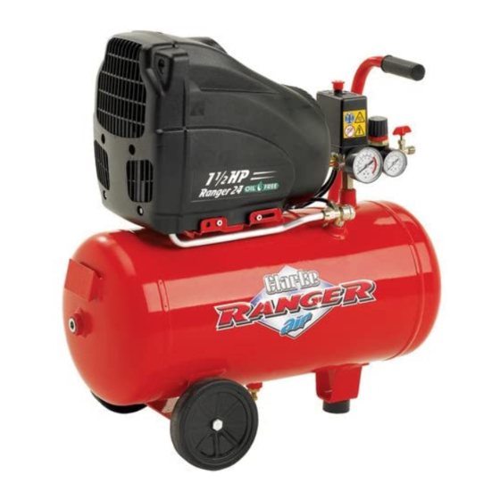
Page 11: Parts Identification
PARTS IDENTIFICATION Support foot Motor housing Drain valve On/Off switch (red button) 10 Compressed air reservoir Main reservoir pressure gauge 11 Transportation wheel Pressure regulator 12 Data plate Regulator locking ring 13 Pressure regulator and cut-out Output pressure gauge 14 Outlet tap Trolley handle... -
Page 12: Assembly
ASSEMBLY WARNING! Before assembling and using the air compressor, make sure that you have read and understood all of the safety instructions. Installation Take care when lifting the compressor from the packaging. CAUTION! Do not lift the compressor by the pressure regulator and cut-out. Get assistance if necessary. - Page 13 ASSEMBLY Locating the air compressor This compressor should be positioned on a stable, flat surface (or one with a maximum inclination of 15 ). See figure 3, and ensure that it is copletely stable. Do not cover or box in the compressor. Always position it with good all round ventilation.
-
Page 14: Preperation For Use
PREPARING FOR USE Before connecting your compressor to the mains supply, check the following:- • The mains voltage is 230V. • The ON/OFF switch is in the OFF (lower) position. • The pressure regulator should be set at its lowest setting, i.e. turned fully anticlockwise. -
Page 15: Operating Instructions
OPERATING INSTRUCTIONS Switching the air compressor ON The compressor will make a continuous loud noise when the tank is charging - this is normal. Lift the red On/Off switch located on top of the pressure regulator to switch the compressor ON. •... - Page 16 OPERATING INSTRUCTIONS The illustration below shows the pressure regulator locked at 6 bar. • Never set the pressure higher than the rated pressure of the attachments being used, as there is a risk of bursting and resultant injury. To increase the output pressure from this preset value you will need to intentionally loosen the locking ring.
-
Page 17: Reset Button
OPERATING INSTRUCTIONS Switching the air compressor OFF To switch the air compressor off, Close the outlet tap and press down the on/off switch (red button) located on top of the air compressor. Switch off the mains supply and remove the plug. •... - Page 18 OPERATING INSTRUCTIONS Draining the reservoir CAUTION! It is important to drain the reservoir before storage. Switch the air compressor off, by pressing down the red On/Off button, and remove the plug from the mains supply. • Place a suitable container beneath the compressor to catch any condensation.
-
Page 19: Routine Maintenance
ROUTINE MAINTENANCE IMPORTANT: Before carrying out any maintenance, always disconnect the compressor from the mains supply, drain the air receiver and, if necessary, allow the machine to cool down before starting work. Daily Drain the tank After use, always open the drain valve to ensure that any liquid that may have condensed, is drained off. - Page 20 ROUTINE MAINTENANCE Every six months • Make sure that all bolts are securely tightened. • Clean all the external parts of the compressor. Non Return Valve Examine the non-return valve, and replace the gasket and valve if necessary Figure 12 Figure 13...
-
Page 21: Troubleshooting
If any fault appears, the reason for which is not immediately obvious, we recommend that you contact your local CLARKE dealer. . t r l i s y l l . -
Page 22: Specifications
SPECIFICATIONS Electrical Supply ........230 V, 1 Phase 50Hz Max. Operating Pressure ....... 8 bar (116 lbf/in Motor Rating ........... 1.5 HP Air Displacement ........4.4 cuft/min Air Receiver ..........24 litre Net Weight ..........21kg Dimensions ( L x W x H ) ......585 x 285 x 595 mm Duty Cycle .......... - Page 23 SPARE PARTS AND SERVICE For Spare Parts and Service,please contact your nearest dealer, or CLARKE International, on one of the following numbers. PARTS & SERVICE TEL: 020 8988 7400 PARTS & SERVICE FAX: 020 8558 3622 e-mail as follows: PARTS: Parts@clarkeinternational.com SERVICE: Service@clarkeinternational.com...
-
Page 24: Parts Diagram
PARTS DIAGRAM... -
Page 25: Parts List
PARTS LIST Description Part No. Description Part No. FRONT HOUSING FN116ZQ0002 TAPPING SCREW FN014013042 CRANKPIN FN116HP0005 WHEEL SPINDLE FN168HQ0004 WASHER FN130203225 WHEEL FN020188000 CRANK FN116ZQ0005 FN014003005 SHAFT FN116ZQ0004 DRAIN VALVE FN022021000 CASING FN116120006 CUSHION FN020146000 CYLINDER GASKET FN116120013 PUMP OL1850 230V/50Hz FN516ZQ01604 CYLINDER FN116ZQ0003 KNOB...
Need help?
Do you have a question about the RANGER 24 and is the answer not in the manual?
Questions and answers