Table of Contents
Advertisement
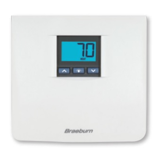
Premier Series
Single Stage Heat / Cool
MODEL
3000
Conventional and Heat Pump
Multi-Stage 2 Heat / 2 Cool
MODEL
3200
Conventional and Heat Pump
Before Installing, Programming or Operating,
PLEASE READ ALL INSTRUCTIONS
Specifications
1
2
3
4
5
WARNING
Important Safety Information
• Always turn off power to the air conditioning or heating system prior to
installing, removing, cleaning or servicing thermostat.
• This thermostat requires either 24 Volts AC Power or two (2) properly installed
"AA" alkaline batteries for normal operation and control of the heating or
cooling system.
• This thermostat should only be used as described in this manual. Any other
use is not recommended and will void the warranty.
1
Specifications
• Electrical Rating: 24 Volt AC (18-30 Volt AC)
1 amp maximum load per terminal
2 amp total maximum load (all terminals) (Model 3000)
3 amp total maximum load (all terminals) (Model 3200)
• Control Range: 45˚ - 90˚ F (7˚ - 32˚ C)
• Accuracy: +/- 1˚ F (+/- .5˚ C)
• AC Power: 18-30 Volt AC
• DC Power: 3.0 Volt DC (2 AA Alkaline batteries included)
©2011 Braeburn Systems LLC • All Rights Reserved. 3000-100-010
Additional Operation
6
Features
7
Trouble Shooting
8
9
1
Specifications
• Model 3000: Compatibility with low voltage single stage gas, oil or electric
heating or cooling systems, including single stage heat pumps; can also
be used on 250mv to 750mv millivolt heating only systems.
• Model 3200: Compatibility with low voltage multi-stage gas, oil or electric
heating or cooling systems, including multi-stage heat pumps.
• Terminations, Model 3000: Rc, Rh, B, O, Y, W, G, C
Terminations, Model 3200: R, O, B, C, Y1, Y2, E/W1, W2, G, L
2
Installation
Replacing Existing Thermostat
1. Always turn off power to the air conditioning or heating system prior to
removing existing thermostat.
2. Remove the cover of your old thermostat and locate the wire terminals.
Do not remove wires from terminals until step 3 is completed.
3. Using small pieces of masking tape, label wires prior to removal from
terminals. Use the chart below to determine the new terminal designations
for your new thermostat.
Old Terminal from
New Terminal for
Existing Thermostat
New Thermostat
(Model 3000)
V or Rc
Rc
M, 4, Rh, or R
Rh
R, V-VR or VR-R
G or F
G
H, W or 4
W
W1, W2, W-U or E
W2
Y
Y
Y, Y1 or M
Y2
B
B
O
O
C
C
L or X
4. After labeling and removing all wires from terminals, unscrew the existing
thermostat sub-base from wall. Secure wires to prevent them from slipping into
the hole in the wall.
cont.
New Terminal for
Terminal
New Thermostat
Description
(Model 3200)
Cooling
Transformer
Heating
Transformer
R
24 VAC
G
Fan Control
Heating Control
E/W1
Emergency Heat /
1st Stage Heat
W2
2nd Stage Heat
Cooling Control
Y1
1st Stage
Compressor
Y2
2nd Stage
Compressor
B
Reversing Valve
(Heating)
O
Reversing Valve
(Cooling)
C
24 VAC Common
L
System Status LED
1
Advertisement
Table of Contents
Troubleshooting

Related Manuals for Braeburn 3000


Summary of Contents for Braeburn 3000
- Page 1 Specifications cont. • Model 3000: Compatibility with low voltage single stage gas, oil or electric Premier Series heating or cooling systems, including single stage heat pumps; can also be used on 250mv to 750mv millivolt heating only systems. Non-Programmable Thermostats •...
-
Page 2: Testing Your New Thermostat
Installation cont. cont. NOTE–MODEL 3000: This thermostat is designed for use with 24 Volt-AC low 18. Attach front body of thermostat to sub-base of thermostat, being careful voltage single stage gas, oil or electric heating or cooling systems, including to align the terminal pins on the front body with the terminal block on single stage heat pumps and can also be used on 250mv to 750mv millivolt the sub-base. -
Page 3: Temperature Adjustment
8. Place the fan switch in the AUTO position. The system blower should stop. For the model 3000, the next setting is the Residual Cooling Fan Delay, or wait 5 seconds for the thermostat to return to the normal operating mode. - Page 4 Temperature Adjustment Additional Operation Features cont. cont. Compressor Protection Feature 2. The display will return to normal operating mode when the or buttons are released. The SET indicator will turn off, indicating that the current temperature This thermostat includes an automatic compressor protection feature to avoid shown in the display is the room temperature.
-
Page 5: Battery Replacement
Additional Operation Features Troubleshooting cont. cont. COOL: This will turn on whenever the Symptom: Thermostat turns on heating instead of cooling or cooling instead system switch is in the cool mode. of heating. “COOL” will flash when the cooling Potential Solution: Check thermostat wiring to make sure that the heating system is running. -
Page 6: Wiring Diagrams
Troubleshooting Wiring Diagrams cont. cont. MODEL 3000: Conventional Systems (Dual Transformer) Symptom: Cannot program a set point temperature higher than 90˚ F (32˚ C). Potential Solution: This is above the normal thermostat temperature setting Rc Rh range of 45˚ to 90˚ F (7˚ to 32˚ C). -
Page 7: Limited Warranty
Neutral Braeburn installation and operating instructions. Braeburn Systems LLC agrees to repair or replace at its option any Braeburn thermostat 24 VAC 120 VAC under warranty provided it is returned postage prepaid to our warranty facility in a padded carton within the warranty period, with proof of the original date of purchase and a brief description of the malfunction.
Need help?
Do you have a question about the 3000 and is the answer not in the manual?
Questions and answers