Table of Contents
Advertisement
Chapter 1. Getting
Started
Getting Started
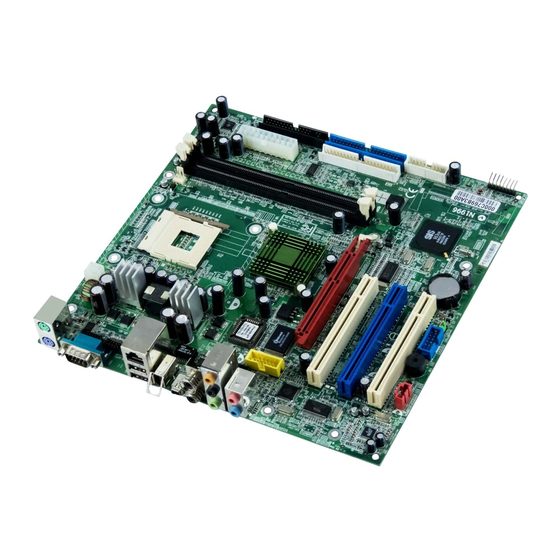
Thank you for purchasing the MS-6785 v1.X Micro ATX
mainboard. The MS-6785 is based on SiS
chipsets for optimal system efficiency. Designed to fit the ad-
vanced Intel
MS-6785 delivers a high performance and professional desktop
platform solution.
®
®
Pentium
4 processors in the 478 pin package, the
Getting Started
®
®
648FX & SiS
963
1-1
Advertisement
Table of Contents

Related Manuals for MSI MS-6785


Summary of Contents for MSI MS-6785
-
Page 1: Chapter 1. Getting
Getting Started Chapter 1. Getting Started Getting Started Thank you for purchasing the MS-6785 v1.X Micro ATX ® ® mainboard. The MS-6785 is based on SiS 648FX & SiS chipsets for optimal system efficiency. Designed to fit the ad- ®... -
Page 2: Mainboard Specifications
MS-6785 M-ATX Mainboard Mainboard Specifications Socket 478 for P4 processors with 400/533/800 MHz (100/133/200MHz QDIR). Core frequency up to 3.2GHz. Chipset ® 648FX (839 pin BGA) ® ® - Supports Intel Pentium 4 processors with data transfer rate up to 800 MHz. - Page 3 Getting Started On-Board Peripherals On-Board Peripherals include: - One floppy port supports 2 FDDs with 360K, 720K, 1.2M, 1.44M and 2.88Mbytes - One serial port (COM A) - One parallel port supports SPP/EPP/ECP mode (Optional) - One RJ-45 LAN port - Vertical audio ports - One RCA_SPDIF In &...
-
Page 4: Mainboard Layout
MS-6785 M-ATX Mainboard Mainboard Layout Top : mouse CPUFAN1 Bottom: keyboard JPW1 JLPT1 T: RJ45 LAN jack B: USB ports 1394 port Mini1394 port T:SPDIF in B:SPDIF out 648FX BIOS Line-Out Line-Out Line-Out Line-Out Line-Out Line-Out Winbond T:Mic 83697HF B:Line-In... -
Page 5: Chapter 2. Hardware
Hardware Setup Chapter 2. Hardware Setup Hardware Setup This chapter provides you with the information about hard- ware setup procedures. While doing the installation, be careful in holding the components and follow the installation procedures. For some components, if you install in the wrong orientation, the components will not work properly. -
Page 6: Quick Components Guide
MS-6785 M-ATX Mainboard Quick Components Guide CPU, p.2-3 CPUFAN1, p.2-17 JPW1, p.2-9 DIMM1/2, p.2-7 CONN1, p.2-9 FDD1, Back Panel p.2-15 I/O, p.2-10 IDE2, p.2-16 IDE1, J7, p.2-23 p.2-16 J9, p.2-20 AGP Slot, p.2-25 JUSB1, p.2-19 JSPDIF1, p.2-21 PCI Slots, p.2-25 JVIDEO1, p.2-18... -
Page 7: Central Processing Unit (Cpu)
CPU core speed Host Clock x Core/Bus ratio 100MHz x 14 1.4 GHz MSI Reminds You... Overheating Overheating will seriously damage the CPU and system, al- ways make sure the cooling fan can work properly to protect the CPU from overheating. -
Page 8: Cpu Installation Procedures For Socket 478
MS-6785 M-ATX Mainboard CPU Installation Procedures for Socket 478 1. Please turn off the power and unplug the power cord before Open Lever installing the CPU. 2. Pull the lever sideways away Sliding 90 degree Plate from the socket. Make sure to raise the lever up to a 90-de- gree angle. -
Page 9: Installing The Cpu Fan
Hardware Setup Installing the CPU Fan As processor technology pushes to faster speeds and higher performance, thermal management becomes increasingly important. To dissipate heat, you need to attach the CPU cooling fan and heatsink on top of the CPU. Follow the instructions below to install the Heatsink/Fan: 1. - Page 10 MS-6785 M-ATX Mainboard 5. Connect the fan power cable from the mounted fan to the 3-pin fan power connector on the board. fan power cable NOTES...
-
Page 11: Introduction To Ddr Sdram
Hardware Setup Memory The mainboard provides 2 slots for 184-pin DDR SDRAM DIMM (Double In-Line Memory Module) modules and supports the memory size up to 2GB. You can install PC2700/DDR333, PC2100/DDR266 or PC1600/ DDR200 modules on the DDR DIMM slots (DIMM 1~2). DDR DIMM Slots (DIMM 1~2) Introduction to DDR SDRAM... -
Page 12: Dimm Module Combination
MS-6785 M-ATX Mainboard DIMM Module Combination Install at least one DIMM module on the slots. Memory modules can be installed on the slots in any order. You can install either single- or double- sided modules to meet your own needs. -
Page 13: Power Supply
Hardware Setup Power Supply The mainboard supports ATX power supply for the power system. Be- fore inserting the power supply connector, always make sure that all compo- nents are installed properly to ensure that no damage will be caused. ATX 20-Pin Power Connector: CONN1 This connector allows you to connect to an ATX power supply. -
Page 14: Back Panel
MS-6785 M-ATX Mainboard Back Panel The back panel provides the following connectors: 6 Channel L-Out Mouse SPDIF-In IEEE1394 Ports Keyboard COM A SPDIF-Out L-In Mouse/Keyboard Connector ® The mainboard provides a standard PS/2 mouse/keyboard mini DIN ® ® connector for attaching a PS/2 mouse/keyboard. -
Page 15: Spdif Connectors
Hardware Setup SPDIF Connectors The SPDIF connectors privided on the back pannel can be used to con- nect your digital audio equipment. SPDIF SPDIF Serial Port Connector: COM A The mainboard offers one 9-pin male DIN connectors as serial port COM A. -
Page 16: Parallel Port Connector: Lpt1
MS-6785 M-ATX Mainboard Parallel Port Connector: LPT1 The mainboard provides a 25-pin female centronic connector as LPT. A parallel port is a standard printer port that supports Enhanced Parallel Port (EPP) and Extended Capabilities Parallel Port (ECP) mode. Pin Definition... -
Page 17: Usb Connectors
Hardware Setup RJ-45 LAN Jack (Optional) The mainboard provides one standard RJ-45 jack for connection to Lo- cal Area Network (LAN). You can connect a network cable to the LAN jack. Pin Definition SIGNAL DESCRIPTION Transmit Differential Pair Transmit Differential Pair RJ-45 LAN Jack Receive Differential Pair Not Used... -
Page 18: Audio Port Connectors
MS-6785 M-ATX Mainboard IEEE1394 Ports The mainboard provides two IEEE 1394 ports. The mini IEEE1394 port is designed for you to connect the IEEE1394 device with external power. The standard IEEE1394 port connects to IEEE1394 devices without external power. The IEEE1394 high-speed serial bus complements USB by providing... -
Page 19: Floppy Disk Drive Connector: Fdd1
Hardware Setup Connectors The mainboard provides connectors to connect to FDD, IDE HDD, case, modem, LAN, USB Ports, IR module and CPU/System/Power Supply FAN. Floppy Disk Drive Connector: FDD1 The mainboard provides a standard floppy disk drive connector that sup- ports 360K, 720K, 1.2M, 1.44M and 2.88M floppy disk types. -
Page 20: Hard Disk Connectors: Ide1 & Ide2
MS-6785 M-ATX Mainboard Hard Disk Connectors: IDE1 & IDE2 The mainboard has a 32-bit Enhanced PCI IDE and Ultra ATA 33/66/ 100/133 controller that provides PIO mode 0~4, Bus Master, and Ultra ATA 33/66/100/133 function. You can connect up to four hard disk drives, CD- ROM, 120MB Floppy (reserved for future BIOS) and other devices. - Page 21 GND. If the mainboard has a System Hardware Monitor chipset on-board, you must use a specially designed fan with speed sensor to take advantage of the CPU fan control. SENSOR +12V CPUFAN1 MSI Reminds You... Always consult the vendors for proper CPU cooling fan. 2-17...
- Page 22 MS-6785 M-ATX Mainboard CD-In Connector: JVIDEO1 The connector is for CD-ROM video connector. JVEDIO1 Front Panel Connector: F_P1 The mainboard provides one front panel connector for electrical con- nection to the front panel switches and LEDs. PS-ON PWR_LED HDD_LED Reset...
-
Page 23: Front Usb Connector: Jusb1
Hardware Setup Front USB Connector: JUSB1 The mainboard provides one USB 2.0 pin header JUSB1 (optional USB ® 2.0 bracket available) that is compliant with Intel I/O Connectivity Design Guide. USB 2.0 technology increases data transfer rate up to a maximum throughput of 480Mbps, which is 40 times faster than USB 1.1, and is ideal for connecting high-speed USB interface peripherals such as USB HDD, dig- ital cameras, MP3 players, printers, modems and the like. - Page 24 MS-6785 M-ATX Mainboard Joystick/Game Connector: CN8 (Optional) You can connect a joystick or game pad to this connector. J9 Pin Definition Description Description FVCC5 (power) Key pin 2-20...
- Page 25 Hardware Setup SPDIF Connector: JSPDIF1 The connector is used to connect an optional bracket for SPDIF (Sony & Philips Digital Interconnect Format) digital audio transmission. JSPDIF1 JSPDIF1 Pin Definition Description Description VCC5 VCC3 SPDIF-O SPDIF-I 2-21...
-
Page 26: Front Panel Audio Connector: Jaudio1
MS-6785 M-ATX Mainboard Front Panel Audio Connector: JAUDIO1 The JAUDIO1 front panel audio connector allows you to connect front panel audio devices if available. JAUDIO1 JAUDIO1 Pin Definition Description Description Speaker_R Front_R Speaker_L Front_L MIC_IN Line_Next_R MIC_IN_S Line_Next_L MSI Reminds You... - Page 27 Hardware Setup IEEE 1394 Connector: J9 (Optional) The mainboard provides one IEEE1394 connector with housing that allows you to connect optional IEEE 1394 ports. Pin Definition SIGNAL SIGNAL IEGND TPA0- TPA0+ Power Power TPB0+ TPB0- IEGND 2-23...
- Page 28 MS-6785 M-ATX Mainboard Print Port: JLPT This mainboard provides a pin header, JLPT, for connecting a printer. JLPT Pin Definition DESCRIPTION STROBE DATA0 DATA1 DATA2 DATA3 DATA4 DATA5 DATA6 DATA7 ACK# BUSY SELECT AUTO FEED# ERR# INIT# SLIN# 2-24...
-
Page 29: Jumpers
JBAT1 Keep Data Clear Data MSI Reminds You... You can clear CMOS by shorting 2-3 pin while the system is off. Then return to 1-2 pin position. Avoid clearing the CMOS while the system is on; it will damage the mainboard. -
Page 30: Pci (Peripheral Component Interconnect) Slots
MS-6785 M-ATX Mainboard Slots The motherboard provides one AGP slot and three 32-bit Master PCI bus slots. AGP Slot PCI Slots AGP (Accelerated Graphics Port) Slot The AGP slot allows you to insert the AGP graphics card. AGP is an interface specification designed for the throughput demands of 3D graphics. -
Page 31: Pci Interrupt Request Routing
Hardware Setup PCI Interrupt Request Routing The IRQ, acronym of interrupt request line and pronounced I-R-Q, are hardware lines over which devices can send interrupt signals to the microprocessor. The PCI IRQ pins are typically connected to the PCI bus INT A# ~ INT D# pins as follows: Order 1 Order 2...