Sign In
Upload
Download
Table of Contents
Contents
Add to my manuals
Delete from my manuals
Share
URL of this page:
HTML Link:
Bookmark this page
Add
Manual will be automatically added to "My Manuals"
Print this page
×
Bookmark added
×
Added to my manuals
Manuals
Brands
MSI Manuals
Motherboard
KM4M Series
Manual
MSI KM4M Series Manual
M-atx mainboard
Hide thumbs
Also See for KM4M Series
:
Owner's manual
(74 pages)
1
2
3
4
Table Of Contents
5
6
7
8
9
10
11
12
13
14
15
16
17
18
19
20
21
22
23
24
25
26
27
28
29
30
31
32
33
34
35
36
37
38
39
40
41
42
43
44
45
46
47
48
49
50
51
52
53
54
55
56
57
58
59
60
61
62
63
64
65
66
67
68
69
70
71
72
73
74
75
76
77
78
79
80
81
82
83
84
85
86
87
88
89
90
91
92
93
94
95
page
of
95
Go
/
95
Contents
Table of Contents
Troubleshooting
Bookmarks
Table of Contents
FCC-B Radio Frequency Interference Statement
Copyright Notice
Revision History
Technical Support
Safety Instructions
Table of Contents
Chapter 1. Getting Started
Mainboard Specifications
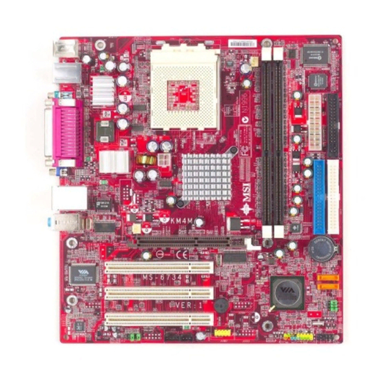
Mainboard Layout
Chapter 2. Hardware Setup
Quick Components Guide
Central Processing Unit: CPU
CPU Core Speed Derivation Procedure
Thermal Issue for CPU
CPU Installation Procedures for Socket 462
Installing AMD Athlon CPU (Socket 462) Cooler Set
CPU Clock Frequency Selection through BIOS
Memory
Memory Speed/Cpu FSB Support Matrix
DIMM Module Combination
Installing DDR Modules
Power Supply
ATX 20-Pin Power Connector: CONN1
ATX 12V Power Connector: JPW1
Back Panel
Mouse Connector
Keyboard Connector
USB Connectors
Parallel Port Connector: LPT1
LAN Jack (Optional)
IEEE1394 Port
VGA DB 15 Pin Connector
Audio Port Connectors
Connectors
Floppy Disk Drive Connector: FDD1
Hard Disk Connectors: IDE1 & IDE2
Fan Power Connectors: CPUFA1/SYSFA1
Front Panel Connectors: JFP1 & JFP2
Front Panel Audio Connector: JAUD1
Front USB Connectors: JUSB2, JUSB3 & JUSB4(Reserved)
IEEE 1394 Connectors: J1394_1 & J1394_2
CD-In Connector: JCD1
SPDIF-Out Connector: JSP1
Irda Infrared Module Header: JIR1
Chassis Intrusion Switch Connector: JCI1
SM Bus Connector: J1
Jumpers
Clear CMOS Jumper: JBAT1
CPU Frequency Jumpers: SW1 & SW2
Slots
AGP (Accelerated Graphics Port) Slot
PCI (Peripheral Component Interconnect) Slots
PCI Interrupt Request Routing
Chapter 3. BIOS Setup
Entering Setup
Control Keys
Getting Help
The Main Menu
Standard CMOS Features
Advanced BIOS Features
Advanced Chipset Features
Integrated Peripherals
PNP/PCI Configurations
PC Health Status
Frequency/Voltage Control
Load Fail-Safe/Optimzed Defaults
Set Supervisor/User Password
Appendix: Using 4- or 6-Channel Audio Function
Installing the Audio Driver
Using 4- or 6-Channel Audio Function
Testing the Connected Speakers
Playing Karaok
Troubleshooting
Glossary
Advertisement
Quick Links
1
Mainboard Specifications
2
Front Panel Connectors: Jfp1 & Jfp2
3
Front Panel Audio Connector: Jaud1
4
Front Usb Connectors: Jusb2, Jusb3 & Jusb4(Reserved)
Download this manual
KM4M Series
MS-6734 (v1.X) M-ATX Mainboard
Version 1.0
G52-M6734X1
i
Table of
Contents
Previous
Page
Next
Page
1
2
3
4
5
Advertisement
Table of Contents
Need help?
Do you have a question about the KM4M Series and is the answer not in the manual?
Ask a question
Questions and answers
Related Manuals for MSI KM4M Series
Motherboard MSI G52-M6734XD Owner's Manual
M-atx mainboard (74 pages)
Motherboard MSI KM3M-V Series Instruction Manual
Msi km3m-v motherboard: instruction manual (102 pages)
Motherboard MSI KM2M Combo User Manual
Ms-6738 (v1.x) micro atx mainboard (89 pages)
Motherboard MSI 770 C45 - AM3 AMD 770 HDMI Motherboard User Manual
K8n neo4 series ms-7125 (v1.x) atx mainboard (135 pages)
Motherboard MSI K9N2 SLI PLATINUM - Motherboard - ATX User Manual
Ms-7374 (v1.x) mainboard (131 pages)
Motherboard MSI K8NGM-V Series Instruction Manual
Msi k8ngm-v motherboard: instruction manual (104 pages)
Motherboard MSI KT4A-V Instruction Manual
Msi kt4a-v motherboard: instruction manual (66 pages)
Motherboard MSI KT6-V User Manual
(v1.x) atx mainboard (69 pages)
Motherboard MSI MS-7021 Manual
Atx mainboard (69 pages)
Motherboard MSI K7T266 Pro Manual
(99 pages)
Motherboard MSi K8MM3 Series User Manual
Ms-7181 (v2.x) micro-atx mainboard (107 pages)
Motherboard MSi K9N Neo V2 Series User Manual
Ms-7369 v1.x mainboard (117 pages)
Motherboard MSI K8N Diamond User Manual
V1.0 atx mainboard (144 pages)
Motherboard MSI K8N Diamond Plus Series User Manual
V1.x atx mainboard (122 pages)
Motherboard MSI KA780G Series User Manual
Ms-7526 (v1.x) mainboard (137 pages)
Motherboard MSi MS-6380 User Manual
Atx mainboard (105 pages)
This manual is also suitable for:
Ms-6734
Table of Contents
Print
Rename the bookmark
Delete bookmark?
Delete from my manuals?
Login
Sign In
OR
Sign in with Facebook
Sign in with Google
Upload manual
Upload from disk
Upload from URL


Need help?
Do you have a question about the KM4M Series and is the answer not in the manual?
Questions and answers