Table of Contents
Advertisement
Quick Links
Advertisement
Table of Contents

Related Manuals for Global American LGA 775 Socket


Summary of Contents for Global American LGA 775 Socket
- Page 1 2807940 User’s Manual Micro ATX Motherboard with LGA 775 Socket Version 1.
- Page 2 2807940 uATX Motherboard Copyrights This document is copyrighted and all rights are reserved. It does not allow any non authorization in copied, photocopied, translated or reproduced to any electronic or machine readable form in whole or in part without prior written consent from the manufacturer.
- Page 3 2807940 uATX Motherboard Manual Conventions WARNING! Warnings appear where overlooked details may cause damage to the equipment or result in personal injury. Warnings should be taken seriously. Warnings are easy to recognize. The word “warning” is written as “WARNING,” both capitalized and bold and is followed by text.
- Page 4 2807940 uATX Motherboard CAUTION: This is an example of a caution message. Failure to adhere to cautions messages may result in permanent damage to the 2807940. Please take caution messages seriously. NOTE: These messages inform the reader of essential but non-critical information. These messages should be read carefully as any directions or instructions contained therein can help avoid making mistakes.
-
Page 5: Packing List
NOTE: If any of the components listed in the checklist below are missing, please do not proceed with the installation. Please contact the Global American, Inc. at (800) 833-8999 or link to Technical Support. The items listed below should all be included in the 2807940 package. -
Page 6: Table Of Contents
2807940 uATX Motherboard Table of Contents INTRODUCTION..................... 1 1.1 O ........................2 VERVIEW 1.1.1 2807940 Features ....................3 1.2 2807940 O ....................3 VERVIEW 1.2.1 2807940 Overview Photo................... 3 1.2.2 2807940 Peripheral Connectors and Jumpers ..........4 1.2.3 Technical Specifications..................6 DETAILED SPECIFICATIONS ................ - Page 7 2807940 uATX Motherboard ® 2.5.4 Intel ICH9DO Ethernet Controller ..............20 2.5.4.1 Intel® 82566DM Gigabit LAN Connect Device........21 ® 2.5.5 Intel ICH9DO Low Pin Count (LPC) Interface..........22 ® 2.5.6 Intel ICH9DO PCI Interface................23 ® 2.5.7 Intel ICH9DO PCIe x4 Bus................23 ®...
- Page 8 2807940 uATX Motherboard 2.10 E ............. 37 NVIRONMENTAL AND OWER PECIFICATIONS 2.10.1 System Monitoring ..................37 2.10.2 Operating Temperature and Temperature Control......... 37 2.10.3 Power Consumption..................38 UNPACKING ......................39 3.1 A ..................40 STATIC RECAUTIONS 3.2 U ......................40 NPACKING 3.2.1 Unpacking Precautions..................
- Page 9 2807940 uATX Motherboard 4.3 E ......... 65 XTERNAL ERIPHERAL NTERFACE ONNECTOR ANEL 4.3.1 Audio Connectors..................... 65 4.3.2 Keyboard/Mouse Connector ................66 4.3.3 LAN and Dual USB Combo Connectors............67 4.3.4 Parallel Port, Serial Port and VGA Combo Connector........69 INSTALLATION ....................72 5.1 A ..................
- Page 10 2807940 uATX Motherboard 5.8.2 LAN Connection (Single Connector) ............... 97 5.8.3 Parallel Device Connection................98 5.8.4 PS/2 Keyboard and Mouse Connection ............99 5.8.5 Serial Device Connection ................100 5.8.6 USB Device Connection................. 101 5.8.7 VGA Monitor Connection ................102 ®...
- Page 11 2807940 uATX Motherboard ® F.3 A ........... 133 CCESSING THE NTEL ATRIX TORAGE ANAGER F.4 RAID C ..................134 ONFIGURATION F.4.1 Creating a RAID Volume................134 F.4.2 Deleting a RAID Volume ................139 F.4.3 Resetting a Disk to Non-RAID ............... 141 F.4.4 Exiting the Matrix Storage Manager .............
- Page 12 2807940 uATX Motherboard List of Figures Figure 1-1: 2807940 uATX Motherboard..................2 Figure 1-2: 2807940 Overview [Front View] ................4 Figure 2-1: 2807940 Dimensions (mm)..................9 Figure 2-2: External Interface Panel Dimensions (mm)............10 Figure 2-3: Data Flow Block Diagram..................11 Figure 2-4: Front Side Bus (FSB) ....................15 Figure 2-5: DDR2 DIMM Sockets ....................15 Figure 2-6: VGA Connector ......................18 Figure 2-7: DMI Chip-to-Chip Connection.................18...
- Page 13 2807940 uATX Motherboard Figure 4-8: 34-pin FDD Connector Location ................54 Figure 4-9: Front Audio Connector Location (10-pin) .............55 Figure 4-10: Front Panel Connector Pinout Locations (14-pin)..........57 Figure 4-11: Infrared Connector Location.................58 Figure 4-12: PCIe Power Connector Location ................59 Figure 4-13: SATA Drive Connector Locations ................60 Figure 4-14: Serial Connector Location ..................61 Figure 4-15: SPDIF Connector Location ...................62 Figure 4-16: TPM Connector Location ..................63...
- Page 14 2807940 uATX Motherboard Figure 5-16: PCIe x16 Installation ....................95 Figure 5-17: Audio Connectors ....................97 Figure 5-18: LAN Connection .....................98 Figure 5-19: Parallel Device Connector..................99 Figure 5-20: PS/2 Keyboard/Mouse Connector ..............100 Figure 5-21: Serial Device Connector..................101 Figure 5-22: USB Device Connection ..................102 Figure 5-23: VGA Connector ....................
- Page 15 2807940 uATX Motherboard List of Tables Table 1-1: Technical Specifications.....................7 Table 2-1: Supported Intel® Core™2 Duo (Conroe) Processors ..........14 Table 2-2: Supported Intel® Celeron® Processors..............14 Table 2-3: Power Consumption....................38 Table 3-1: Package List Contents ....................42 Table 3-2: Package List Contents ....................42 Table 4-1: Peripheral Interface Connectors ................46 Table 4-2: Rear Panel Connectors .....................47 Table 4-3: ATX Power Connector Pinouts ................48...
- Page 16 2807940 uATX Motherboard Table 4-22: USB Port Pinouts.....................68 Table 4-23: Parallel Port Connector Pinouts ................70 Table 4-24: RS-232 Serial Port (COM 1) Pinouts ..............70 Table 4-25: VGA Connector Pinouts..................71 Table 5-1: Jumpers........................86 Table 5-2: Clear CMOS Jumper Settings...................87 Table 5-3: COM Port Pin 9 Setting Jumper Settings..............88 Table 5-4: COM Port Pin 9 Voltage Setting Jumper Settings..........89 Table 5-5: GAI Provided Cables ....................91...
-
Page 17: Introduction
2807940 uATX Motherboard Chapter Introduction Page 1... -
Page 18: Overview
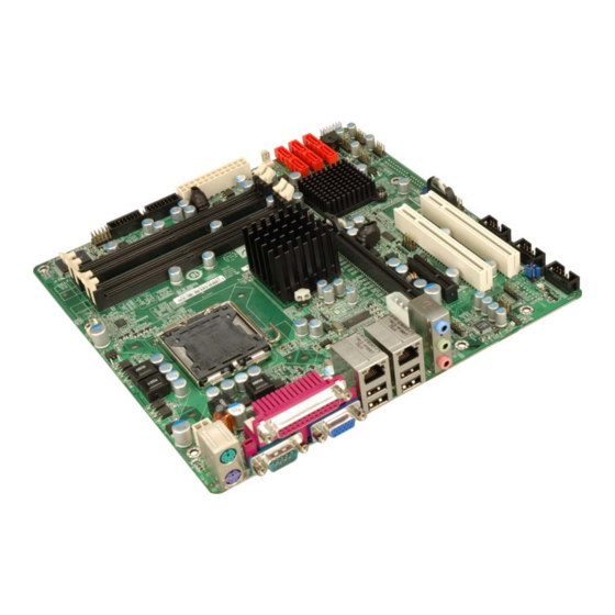
2807940 uATX Motherboard 1.1 Overview Figure 1-1: 2807940 uATX Motherboard The 2807940 uATX form factor motherboard (Figure 1-1) is an LGA775 Intel® Core™2 Quad, Intel® Core™2 Duo or Intel® Celeron® CPU processor platform. Both 45nm core (Wolfdale, Yorkfield) and 65nm core (Conroe) processors are supported. (For a full list of supported processors please refer to Section 2.3) Up to four 2.0 GB 667 MHz or 800 MHz un-buffered DDR2 SDRAM DIMM are supported by the Intel®... -
Page 19: 2807940 Features
2807940 uATX Motherboard 1.1.1 2807940 Features Some of the 2807940 features are listed below. Supports the following Intel® LGA775 processors: Intel® Core™2 Duo (45nm and 65nm) Intel® Core™2 Quad (45nm and 65nm) Intel® Celeron® (65nm) Supports four 240-pin 2 GB 667 MHz or 800 MHz DDR2 DIMMs Six SATA II drives with transfer rates of 3.0 Gbps supported Twelve USB 2.0 devices supported (eight onboard and four on the rear panel) Dual GbE Ethernet connectors... -
Page 20: 2807940 Peripheral Connectors And Jumpers
2807940 uATX Motherboard Figure 1-2: 2807940 Overview [Front View] 1.2.2 2807940 Peripheral Connectors and Jumpers The 2807940 has the following connectors on-board: 1 x ATX power connector 1 x Audio connector 1 x CD in connector 1 x Cooling fan connector, CPU Page 4... - Page 21 2807940 uATX Motherboard 1 x Cooling fan connector, System 1 x CPU power connector 1 x Digital input/output connector 4 x DIMM sockets 1 x Floppy drive connector 1 x Front panel connector 1 x Infrared (IrDA) connector 2 x PCI slots 1 x PCIe x16 slots 1 x PCIe x4 slots 1 x PCIe power connector...
-
Page 22: Technical Specifications
2807940 uATX Motherboard 1.2.3 Technical Specifications 2807940 technical specifications are listed in Table 1-1. See Chapter 2 for details. Specification 2807940 uATX Form Factor LGA775 Intel® Core™2 Quad System CPU LGA775 Intel® Core™2 Duo LGA775 Intel® Celeron® Front Side Bus (FSB) 800 MHz, 1066 MHz or 1333 MHz Northbridge: Intel®... -
Page 23: Table 1-1: Technical Specifications
2807940 uATX Motherboard Four by external connectors SATA Six 3.0 Gb/s SATA II drives supported SATA RAID Levels RAID 0, RAID 1, RAID 5 and RAID 10 Keyboard/mouse By external PS/2 connector through the ITE IT8712F super I/O One 8-bit digital input/output connector; 4-bit input/4-bit output Digital I/O through the ITE IT8712F super I/O Software programmable 1-255 sec. -
Page 24: Detailed Specifications
2807940 uATX Motherboard Chapter Detailed Specifications Page 8... -
Page 25: Dimensions
2807940 uATX Motherboard 2.1 Dimensions 2.1.1 Board Dimensions The dimensions of the board are listed below: Length: 243.84mm Width: 243.84mm Figure 2-1: 2807940 Dimensions (mm) Page 9... -
Page 26: External Interface Panel Dimensions
2807940 uATX Motherboard 2.1.2 External Interface Panel Dimensions External peripheral interface connector panel dimensions are shown in Figure 2-2. Figure 2-2: External Interface Panel Dimensions (mm) Page 10... -
Page 27: Data Flow
2807940 uATX Motherboard 2.2 Data Flow Figure 2-3 shows the data flow between the two on-board chipsets and other components installed on the motherboard and described in the following sections of this chapter. Figure 2-3: Data Flow Block Diagram Page 11... -
Page 28: Compatible Processors
2807940 uATX Motherboard 2.3 Compatible Processors 2.3.1 Supported Processors Overview The 2807940 supports the following Intel® LGA775 processors Intel® Core™2 Quad (Yorkfield) Intel® Core™2 Duo (Wolfdale) Intel® Core™2 Duo (Conroe) Intel® Celeron® (Conroe) 2.3.2 Supported Intel® Core™2 Quad (Yorkfield) Processors The Yorkfield core Intel®... -
Page 29: Supported Intel® Core™2 Duo (Wolfdale) Processors
2807940 uATX Motherboard 2.3.3 Supported Intel® Core™2 Duo (Wolfdale) Processors The Wolfdale core Intel® Core™2 Duo CPU is a 45nm LGA775 processor. NOTE: As of the date of writing this manual (December, 2007), Intel® has not released Wolfdale core Intel® Core™2 Duo processor numbers that are supported by the Intel®... -
Page 30: Supported Intel® Celeron® (Conroe) Processors
2807940 uATX Motherboard Processor # CPU Speed FSB Speed Cache Size E6850 3.0 GHz 1333 MHz 4 MB Table 2-1: Supported Intel® Core™2 Duo (Conroe) Processors 2.3.5 Supported Intel® Celeron® (Conroe) Processors Table 2-1 lists the Conroe core Intel® Celeron® processors supported on the 2807940. All the processors in Table 2-1 are 65nm LGA775 processors with the following features: Execute Disable Bit Intel®... -
Page 31: Intel® Q35 Memory Controller
2807940 uATX Motherboard 1333 MHz The LGA775 socket, Intel® Q35 Northbridge and the FSB are shown in Figure 2-4. Figure 2-4: Front Side Bus (FSB) 2.4.3 Intel® Q35 Memory Controller The memory controller on the Intel® Q35 Northbridge can support up to 8.0 GB of DDR2 SDRAM. -
Page 32: Intel® Q35 Pcie X16 Interface
2807940 uATX Motherboard CAUTION: If more than one DDR2 DIMM is being installed in the system, please purchase two DIMM that have the same capacity and operating frequency. Each DIMM socket can support DIMMs with the following specifications: DDR2 only Un-buffered only 667 MHz or 800 MHz 2.0 GB maximum capacity per DIMM (8.0 GB supported with four DIMM) -
Page 33: Intel® Q35 Graphics And Display Features
2807940 uATX Motherboard 2.4.5 Intel® Q35 Graphics and Display Features NOTE: The Intel® Q35 Graphics and Display Features can be configured in the Northbridge BIOS configuration screen. Please refer to Section Error! Reference source not found. on page Error! Bookmark not defined.. -
Page 34: Intel® Q35 Direct Media Interface (Dmi)
2807940 uATX Motherboard Figure 2-6: VGA Connector Some of the capabilities of the Intel® Q35 analog CRT port are listed below: 400 MHz Integrated 24-bit RAMDAC Up to 2048x1536 @ 75 Hz refresh Hardware Color Cursor Support DDC2B Compliant Interface 2.4.7 Intel®... -
Page 35: Intel ® Ich9Do Southbridge Chipset
2807940 uATX Motherboard Message Signaled Interrupt (MSI) messages SMI, SCI and SERR error indication ® 2.5 Intel ICH9DO Southbridge Chipset ® 2.5.1 Intel ICH9DO Overview Intel® ICH9DO Southbridge is an advanced I/O controller hub (ICH) connected to the Intel® Q35 Northbridge through a DMI connection. The Intel® ICH9DO has six PCIe x1 ports, supports up to twelve USB 2.0 devices, six 3.0 Gbps SATA II drives with Intel®... -
Page 36: Intel® Ich9Do High Definition Audio Implementation
2807940 uATX Motherboard 2.5.3 Intel® ICH9DO High Definition Audio Implementation A RealTek ALC883 High Definition Audio (HDA) codec is interfaced through the Intel® High Definition Audio serial link to the HDA controller integrated on the Intel® ICH9DO. The audio connector is shown in Figure 2-8. Figure 2-8: Audio Connectors ®... -
Page 37: Intel® 82566Dm Gigabit Lan Connect Device
2807940 uATX Motherboard 82566DM connects the Intel® ICH9DO Southbridge integrated GbE controller to an external RJ-45 Ethernet LAN connector to provide GbE access. NOTE: To enable the Intel® ICH9DO GbE Wake-on LAN function, the Wake-on LAN function must be enabled in the BIOS. Please refer to Section Error! Reference source not found. -
Page 38: Intel ® Ich9Do Low Pin Count (Lpc) Interface
2807940 uATX Motherboard through the GLCI and LCI. The Intel® ICH9DO Ethernet controller has its own Media Access Controller (MAC). The Intel® 82566DM Gigabit LAN connect device is shown in Figure 2-9. Figure 2-9: Intel® 82566DM Gigabit LAN Connect Device Some of the features of the Intel®... -
Page 39: Intel ® Ich9Do Pci Interface
2807940 uATX Motherboard The ICH9DO LPC interface complies with the LPC 1.1 specifications. The LPC bus from the ICH9DO is connected to the following components: BIOS chipset Super I/O chipset Trusted Platform Module (TPM) connector ® 2.5.6 Intel ICH9DO PCI Interface The PCI interface on the ICH9DO is compliant with the PCI Revision 2.3 implementation. -
Page 40: Intel ® Ich9Do Sata Controller
2807940 uATX Motherboard ® 2.5.9 Intel ICH9DO SATA Controller NOTE: That SATA drive mode is set in the BIOS. Please refer to the Section Error! Reference source not found. on IDE Configuration on page Error! Bookmark not defined. and Section Error! Reference source not found.on AHCI Configuration on page Error! Bookmark not defined.. -
Page 41: Intel ® Ich9Do Serial Peripheral Interface (Spi) Bios
2807940 uATX Motherboard Figure 2-10: SATA Drive Connectors ® 2.5.10 Intel ICH9DO Serial Peripheral Interface (SPI) BIOS The SPI is connected to an SPI BIOS chip. A licensed copy of AMI BIOS is preinstalled on the SPI BIOS chip. ® 2.5.11 Intel ICH9DO USB Controller ®... -
Page 42: 2807940 Usb Implementation
2807940 uATX Motherboard 2.5.11.2 2807940 USB Implementation All twelve of the Intel® ICH9DO USB ports are implemented on the 2807940. Four USB ports (USB Port 1 to USB Port 4) are connected to four external connectors and eight USB ports (USB Port 5 to USB Port 12) are connected to four 8-pin onboard pin-headers. See Figure 2-11. -
Page 43: Pcie X16 Slot
2807940 uATX Motherboard 2.6.2 PCIe x16 Slot The Intel® Q35 Northbridge chipset has one PCIe x16 port reserved for a PCIe x16 graphics card. The PCIe x16 lane is interfaced to a PCIe x16 slot on the 2807940 motherboard. The PCIe x16 graphics card is then installed on the PCIe x16 slot on the motherboard. -
Page 44: Intel® 82573L Pcie Gbe Controller
2807940 uATX Motherboard Figure 2-13: PCIe x4 Slot 2.6.4 Intel® 82573L PCIe GbE Controller An RJ-45 Ethernet LAN connector is interfaced directly to an Intel® 82573L PCIe GbE controller. The Intel® 82573L PCIe GbE controller is a compact, single-port integrated physical layer (PHY) device with its own Memory Access Controller (MAC) and interfaced to the Intel®... -
Page 45: Pci Bus Components
2807940 uATX Motherboard Programmable host memory Rx buffers (256 B-16 KB) Descriptor ring management hardware for Tx and Rx Mechanism for reducing interrupts from Tx/Rx operations Integrated PHY for 10/100/1000 Mbps (full- and half-duplex) IEEE 802.3ab* auto-negotiation support IEEE 802.3ab PHY compliance and compatibility Tx/Rx IP,TCP,and UDP checksum offloading Tx TCP segmentation IEEE 802.1q* Virtual Local Area Network (VLAN) support with VLAN tag... -
Page 46: Lpc Bus Components
2807940 uATX Motherboard Figure 2-15: PCI Slots 2.8 LPC Bus Components 2.8.1 LPC Bus Overview The LPC bus is connected to components listed below: TPM module connector Super I/O chipset Fintek F81216DG LPC Serial Port Chipset 2.8.2 TPM Module A TPM connector on the 2807940 is interfaced to the Intel® ICH9DO Southbridge through the LPC bus. -
Page 47: Super I/O Chipset
2807940 uATX Motherboard Figure 2-16: TPM Connector The Intel® ICH9DO Southbridge supports TPM version 1.1 and TPM version 1.2 devices for enhanced security. Three TPM are available from GAI. The three GAI TPM are listed below: Infineon TPM module Sinosun TPM module Winbond TPM module For more information about these modules please refer to Chapter 3 or contact the Global.American,.Inc. -
Page 48: Figure 2-17: Ite It8712F Super I/O
2807940 uATX Motherboard Figure 2-17: ITE IT8712F Super I/O The ITE IT8712F is an LPC interface-based Super I/O device that comes with an integrated Environment Controller. Some of the features of the ITE IT8712F chipset are listed below: PC98/99/2001, ACPI and LANDesk Compliant Enhanced Hardware Monitor Fan Speed Controller Single +5V Power Supply... -
Page 49: Super I/O Lpc Interface
2807940 uATX Motherboard 2.8.3.1 Super I/O LPC Interface ® The LPC interface on the Super I/O complies with the Intel Low Pin Count Specification Rev. 1.0. The LPC interface supports both LDRQ# and SERIRQ protocols as well as PCI PME# interfaces. 2.8.3.2 Super I/O 16C550 UARTs The onboard Super I/O has two integrated 16C550 UARTs that can support the following: one standard serial port (COM1) -
Page 50: Super I/O Fan Speed Controller
2807940 uATX Motherboard The FDD controller is interfaced to a FDD connected to the FDD connector on the 2807940. 2.8.3.5 Super I/O Fan Speed Controller The Super I/O fan speed controller enables the system to monitor the speed of the fan. One of the pins on the fan connector is reserved for fan speed detection and interfaced to the fan speed controller on the Super I/O. -
Page 51: Super I/O Watchdog Timer
2807940 uATX Motherboard Enhanced Parallel Port (EPP) mode supported. Compatible with IEEE 1284 specifications Extended Capability Port (ECP) mode supported. Compatible with IEEE 1284 specifications Enhanced printer port back-drive current reduction Printer power-on damage reduction Supports POST (Power-On Self Test) Data Port The parallel port controller is connected to an external DB-26 LPT connector. -
Page 52: Figure 2-18: Lan Connections
2807940 uATX Motherboard Figure 2-18: LAN Connections The first GbE controller, is an Intel® 82537L PCIe GbE controller and is the interface between the Intel® ICH9DO Southbridge controller and the LAN1 RJ-45 Ethernet connector. The second GbE controller is integrated on the Intel® ICH9DO Southbridge and interfaced to the LAN2 RJ-45 Ethernet LAN connector through an Intel®... -
Page 53: Environmental And Power Specifications
2807940 uATX Motherboard 2.10 Environmental and Power Specifications 2.10.1 System Monitoring Three thermal inputs on the 2807940 Super I/O Enhanced Hardware Monitor monitor the following temperatures: System Temperature #1 System Temperature #2 Five voltage inputs on the 2807940 Super I/O Enhanced Hardware Monitor monitors the following voltages: CPU Core DDR2 1.8V... -
Page 54: Power Consumption
2807940 uATX Motherboard Maximum Operating Temperature: 60°C (140°F) A cooling fan and heat sink must be installed on the CPU. Thermal paste must be smeared on the lower side of the heat sink before it is mounted on the CPU. Heat sinks are also mounted on the Northbridge and Southbridge chipsets to ensure the operating temperature of these chips remain low. -
Page 55: Unpacking
2807940 uATX Motherboard Chapter Unpacking Page 39... -
Page 56: Anti-Static Precautions
2807940 uATX Motherboard 3.1 Anti-static Precautions WARNING: Failure to take ESD precautions during the installation of the 2807940 may result in permanent damage to the 2807940 and severe injury to the user. Electrostatic discharge (ESD) can cause serious damage to electronic components, including the 2807940. -
Page 57: Unpacking Checklist
3.3 Unpacking Checklist NOTE: If some of the components listed in the checklist below are missing, please do not proceed with the installation. Contact Global American, Inc. at (800) 833-8999. 3.3.1 Package Contents The 2807940 is shipped with the following components:... -
Page 58: Optional Items
2807940 uATX Motherboard Mini jumper Pack Quick Installation Guide Utility CD Table 3-1: Package List Contents 3.4 Optional Items CPU cooling kit (P/N: 2107695) Infineon TPM module (P/N: 1007790) Sinosun TPM module (P/N: 1007800) Winbond TPM module (P/N: 1007810) Table 3-2: Package List Contents Page 42... -
Page 59: Connector Pinouts
2807940 uATX Motherboard Chapter Connector Pinouts Page 43... -
Page 60: Peripheral Interface Connectors
2807940 uATX Motherboard 4.1 Peripheral Interface Connectors Section 4.1.2 shows peripheral interface connector locations. Section 4.1.2 lists all the peripheral interface connectors seen in Section 4.1.2. 4.1.1 2807940 Layout Figure 4-1 shows the on-board peripheral connectors, rear panel peripheral connectors and on-board jumpers. -
Page 61: Peripheral Interface Connectors
2807940 uATX Motherboard 4.1.2 Peripheral Interface Connectors Table 4-1 shows a list of the peripheral interface connectors on the 2807940. Detailed descriptions of these connectors can be found below. Connector Type Label ATX power connector 24-pin ATX connector ATX1 CD in connector 4-pin header CD_IN1 Cooling fan connector, CPU... -
Page 62: External Interface Panel Connectors
2807940 uATX Motherboard Serial ATA drive connector 7-pin SATA SATA1 Serial ATA drive connector 7-pin SATA SATA2 Serial ATA drive connector 7-pin SATA SATA3 Serial ATA drive connector 7-pin SATA SATA4 Serial ATA drive connector 7-pin SATA SATA5 Serial ATA drive connector 7-pin SATA SATA6 Serial port connector (COM2) -
Page 63: Internal Peripheral Connectors
2807940 uATX Motherboard Connector Type Label Audio connector Audio jack AUDIO_CV1 Ethernet and dual USB combo connector RJ-45 and two USB LAN1_USB01 Ethernet and dual USB combo connector RJ-45 and two USB LAN2_USB23 Mouse or keyboard connector PS/2 KB_MS1 Parallel port, serial port and VGA combo DB-25, DB-9 and 3IN1_DSUB1 connector... -
Page 64: Figure 4-2: Atx Power Connector Pinout Locations
2807940 uATX Motherboard Figure 4-2: ATX Power Connector Pinout Locations PIN NO. DESCRIPTION PIN NO. DESCRIPTION 3.3V 3.3V 3.3V -12V PS_ON Power good 5VSB +12V +12V 3.3V Table 4-3: ATX Power Connector Pinouts Page 48... -
Page 65: Audio Cd In Connector
2807940 uATX Motherboard 4.2.2 Audio CD In Connector CN Label: CD_IN1 CN Type: 4-pin header CN Location: See Figure 4-3 CN Pinouts: See Table 4-4 The 4-pin audio CD in connector is connected to an external audio CD device for the input and output of audio signals from a CD player to the system. -
Page 66: Cpu Power Connector
2807940 uATX Motherboard 4.2.3 CPU Power Connector CN Label: CPU12V1 CN Type: 4-pin power connector (1x4) CN Location: See Figure 4-4 CN Pinouts: See Table 4-5 The 4-pin CPU power connector is connected to an ATX power supply and powers the CPU. -
Page 67: Figure 4-5: Dio Connector Location
2807940 uATX Motherboard CN Location: See Figure 4-5 CN Pinouts: See Table 4-6 The digital input/output connector is managed through a Super I/O chip. The DIO connector pins are user programmable. To see details on how to program the DIO chip, please refer to Appendix B. -
Page 68: Fan Connector, Cpu (12V, 4-Pin)
2807940 uATX Motherboard 4.2.5 Fan Connector, CPU (12V, 4-pin) CN Label: CPU_FAN1 CN Type: 4-pin header (1x4) CN Location: See Figure 4-6 CN Pinouts: See Table 4-7 The CPU cooling fan connector provides a 12V, 500mA current to a CPU cooling fan. The connector has a "rotation"... -
Page 69: Fan Connector, System (+12V, 3-Pin)
2807940 uATX Motherboard 4.2.6 Fan Connector, System (+12V, 3-pin) CN Label: SYS_FAN1 CN Type: 3-pin header (1x3) CN Location: See Figure 4-7 CN Pinouts: See Table 4-8 The system cooling fan connector provides a 12V, 500mA current to a system cooling fan. The connector has a "rotation"... -
Page 70: Floppy Disk Connector (34-Pin)
2807940 uATX Motherboard 4.2.7 Floppy Disk Connector (34-pin) CN Label: FDD1 CN Type: 34-pin header (2x17) CN Location: See Figure 4-8 CN Pinouts: See Table 4-9 The floppy disk connector is connected to a floppy disk drive. Figure 4-8: 34-pin FDD Connector Location PIN NO. -
Page 71: Front Audio Connector
2807940 uATX Motherboard STEP# WRITE DATA# WRITE GATE# TRACK 0# WRITE PROTECT# READ DATA# SIDE 1 SELECT# DISK CHANGE# Table 4-9: 34-pin FDD Connector Pinouts 4.2.8 Front Audio Connector CN Label: FP_AUDIO1 10-pin header (2x5) CN Type: CN Location: See Figure 4-9 CN Pinouts: See Table 4-10 Figure 4-9: Front Audio Connector Location (10-pin) -
Page 72: Front Panel Connector
2807940 uATX Motherboard PIN NO. DESCRIPTION PIN NO. DESCRIPTION MIC_L MIC_R Audio Detect LINE2-R Jack Detection LINE2-L Table 4-10: Front Audio Connector Pinouts 4.2.9 Front Panel Connector CN Label: F_PANEL1 14-pin header (2x7) CN Type: CN Location: See Figure 4-10 CN Pinouts: See Table 4-11 The front panel connector connects to external switches and indicators to monitor and... -
Page 73: Infrared Interface Connector
2807940 uATX Motherboard Figure 4-10: Front Panel Connector Pinout Locations (14-pin) FUNCTION DESCRIPTION FUNCTION DESCRIPTION Power LED Speaker GROUND Power PWRBTN+ SPEAKER Button PWRBTN- Reset HDD LED RESET- IDE LED- GROUND Table 4-11: Front Panel Connector Pinouts (14-pin) 4.2.10 Infrared Interface Connector CN Label: CN Type: 5-pin header (1x5) -
Page 74: Pcie Power Connector
2807940 uATX Motherboard Figure 4-11: Infrared Connector Location PIN NO. DESCRIPTION IR-RX IR-TX Table 4-12: Infrared Connector Pinouts 4.2.11 PCIe Power Connector CN Label: PCIE_12V1 CN Type: 4-pin wafer (1x4) CN Location: See Figure 4-12 CN Pinouts: See Table 4-13 The 4-pin PCIe power connector is connected to a power supply to power the PCIe expansion card. -
Page 75: Sata Drive Connectors
2807940 uATX Motherboard Figure 4-12: PCIe Power Connector Location PIN NO. DESCRIPTION +12V Table 4-13: PCIe Power Connector Pinouts 4.2.12 SATA Drive Connectors CN Label: SATA1, SATA2, SATA3, SATA4, SATA5 and SATA6 CN Type: 7-pin SATA drive connectors (1x7) CN Location: See Figure 4-13 CN Pinouts: See Table 4-14... -
Page 76: Figure 4-13: Sata Drive Connector Locations
2807940 uATX Motherboard The six SATA drive connectors are each connected to second generation SATA drives. Second generation SATA drives transfer data at speeds as high as 3.0 Gbps. The SATA drives can be configured in a RAID configuration. Figure 4-13: SATA Drive Connector Locations PIN NO. -
Page 77: Serial Port Connector (Com2, Com 3 And Com4)
2807940 uATX Motherboard 4.2.13 Serial Port Connector (COM2, COM 3 and COM4) CN Label: COM2, COM3 and COM4 CN Type: 10-pin header (2x5) CN Location: See Figure 4-14 CN Pinouts: See Table 4-15 The 10-pin serial port connector provides a second RS-232 serial communications channel. -
Page 78: Spdif Connector
2807940 uATX Motherboard 4.2.14 SPDIF Connector CN Label: SPDIF1 CN Type: 5-pin header (1x5) CN Location: See Figure 4-15 CN Pinouts: See Table 4-16 Use the SPDIF connector to connect digital audio devices to the system. Figure 4-15: SPDIF Connector Location DESCRIPTION SPDIF OUT SPDIF IN... -
Page 79: Trusted Platform Module (Tpm) Connector
2807940 uATX Motherboard 4.2.15 Trusted Platform Module (TPM) Connector CN Label: TPM1 CN Type: 40-pin header (2x20) CN Location: See Figure 4-16 CN Pinouts: See Table 4-17 The Trusted Platform Module (TPM) connector secures the system on bootup. An optional TPM (see packing list in Chapter 3) can be connected to the TPM connector. -
Page 80: Usb Connectors (Internal)
2807940 uATX Motherboard 4.2.16 USB Connectors (Internal) CN Label: USB45, USB67, USB89 and USB1011 CN Type: 8-pin header (2x4) CN Location: See Figure 4-17 CN Pinouts: See Table 4-18 The 2x4 USB pin connectors each provide connectivity to two USB 1.1 or two USB 2.0 ports. -
Page 81: External Peripheral Interface Connector Panel
2807940 uATX Motherboard 4.3 External Peripheral Interface Connector Panel Figure 4-18 shows the 2807940 external peripheral interface connector (EPIC) panel. The 2807940 EPIC panel consists of the following: 3 x Audio jacks 1 x Parallel port 2 x PS/2 keyboard/mouse connectors 2 x RJ-45 LAN connectors 1 x Serial port connector 4 x USB 2.0 ports... -
Page 82: Keyboard/Mouse Connector
2807940 uATX Motherboard devices. Line Out port (Lime): Connects to a headphone or a speaker. With multi-channel configurations, this port can also connect to front speakers. Microphone (Pink): Connects a microphone. Figure 4-19: Audio Connector 4.3.2 Keyboard/Mouse Connector CN Label: KB_MS1 CN Type: Dual PS/2... -
Page 83: Lan And Dual Usb Combo Connectors
2807940 uATX Motherboard DESCRIPTION DATA VCC5 Table 4-19: PS/2 Connector Pinouts 4.3.3 LAN and Dual USB Combo Connectors CN Label: LAN1_USB01 and LAN2_USB23 CN Type: RJ-45 CN Location: See Figure 4-18 CN Pinouts: See Table 4-20 The 2807940 is equipped with two built-in RJ-45 Ethernet controllers. The controllers can connect to the LAN through two RJ-45 LAN connectors. -
Page 84: Figure 4-21: Rj-45 Ethernet Connector
2807940 uATX Motherboard Figure 4-21: RJ-45 Ethernet Connector The RJ-45 Ethernet connector has two status LEDs, one green and one yellow. The green LED indicates activity on the port and the yellow LED indicates the port is linked. See Table 4-21. LINK LED Activity LED Status... -
Page 85: Parallel Port, Serial Port And Vga Combo Connector
2807940 uATX Motherboard 4.3.4 Parallel Port, Serial Port and VGA Combo Connector CN Label: 3IN1_DSUB1 CN Type: DB-25, DB-9 and DB-15 CN Location: See Figure 4-18 CN Pinouts: See Table 4-23, Table 4-24 and Table 4-25 A 25-pin parallel port connector, a male DB-9 serial port (COM1) and a female DB-15 VGA connector are integrated into a single EPIC connector as shown in Figure 4-18. -
Page 86: Figure 4-23: Com1 Pinout Locations
2807940 uATX Motherboard PRINTER SELECT LN# Table 4-23: Parallel Port Connector Pinouts The male DB-9 COM 1 serial port connector is connected to RS-232 serial communications devices. The connector is show in Figure 4-23 and the pinouts are shown in Table 4-24. Figure 4-23: COM1 Pinout Locations PIN NO. -
Page 87: Figure 4-24: Vga Connector
2807940 uATX Motherboard Figure 4-24: VGA Connector DESCRIPTION DESCRIPTION GREEN BLUE VCC / NC DDC DAT HSYNC VSYNC DDCCLK Table 4-25: VGA Connector Pinouts Page 71... -
Page 88: Installation
2807940 uATX Motherboard Chapter Installation Page 72... -
Page 89: Anti-Static Precautions
2807940 uATX Motherboard 5.1 Anti-static Precautions WARNING: Failure to take ESD precautions during the installation of the 2807940 may result in permanent damage to the 2807940 and severe injury to the user. Electrostatic discharge (ESD) can cause serious damage to electronic components, including the 2807940. -
Page 90: Installation Considerations
2807940 uATX Motherboard 5.2 Installation Considerations NOTE: The following installation notices and installation considerations should be read and understood before the 2807940 is installed. All installation notices pertaining to the installation of the 2807940 should be strictly adhered to. Failing to adhere to these precautions may lead to severe damage of the 2807940 and injury to the person installing the motherboard. -
Page 91: Installation Checklist
2807940 uATX Motherboard When working with the 2807940, make sure that it is disconnected from all power supplies and that no electricity is being fed into the system. Before and during the installation of the 2807940 DO NOT: Remove any of the stickers on the PCB board. These stickers are required for warranty validation. -
Page 92: Unpacking
2807940 uATX Motherboard 5.3 Unpacking 5.3.1 Unpacking Precautions When the 2807940 is unpacked, please do the following: Follow the anti-static precautions outlined in Section 5.1. Make sure the packing box is facing upwards so the 2807940 does not fall out of the box. -
Page 93: Socket Lga775 Cpu Installation
2807940 uATX Motherboard 5.4.1 Socket LGA775 CPU Installation NOTE: Enabling Hyper-Threading Technology on your system requires meeting all of the platform requirements listed below: CPU: An Intel® Processor with HT Technology must be installed Chipset: An Intel® Chipset that supports HT Technology (that has been met by the 2807940) OS: An operating system that has optimizations for HT Technology... -
Page 94: Figure 5-2: Remove The Cpu Socket Protective Shield
2807940 uATX Motherboard To install a socket LGA775 CPU onto the 2807940, follow the steps below: WARNING: When handling the CPU, only hold it on the sides. DO NOT touch the pins at the bottom of the CPU. Step 1: Remove the protective cover. Remove the black protective cover by prying it off the load plate. -
Page 95: Figure 5-3: Open The Cpu Socket Load Plate
2807940 uATX Motherboard Figure 5-3: Open the CPU Socket Load Plate Step 3: Inspect the CPU socket Make sure there are no bent pins and make sure the socket contacts are free of foreign material. If any debris is found, remove it with compressed air. -
Page 96: Socket Lga775 2107695 Cooling Kit Installation
2807940 uATX Motherboard Figure 5-4: Insert the Socket LGA775 CPU Step 8: Close the CPU socket. Close the load plate and engage the load lever by pushing it back to its original position. Secure the load lever under the retention tab on the side of CPU socket. -
Page 97: Figure 5-5: Gai 2107695 Cooling Kit
2807940 uATX Motherboard Figure 5-5: GAI 2107695 Cooling Kit An GAI Socket LGA775 CPU cooling kit shown in Figure 5-5 can be purchased separately. The cooling kit comprises a CPU heat sink and a cooling fan. WARNING: Do not wipe off (accidentally or otherwise) the pre-sprayed layer of thermal paste on the bottom of the 2107695 heat sink. -
Page 98: Dimm Installation
2807940 uATX Motherboard holes. (See Figure 5-6) Figure 5-6: Securing the Heat sink to the PCB Board Step 5: Tighten the screws. Use a screwdriver to tighten the four screws. Tighten each nut a few turns at a time and do not over-tighten the screws. Step 6: Connect the fan cable. -
Page 99: Dimm Purchasing Guidelines
2807940 uATX Motherboard 5.4.3.1 DIMM Purchasing Guidelines WARNING: Only use DDR2 DIMMs. If DDR DIMMs are used the system may be irreparably damaged. When purchasing the DDR2 DIMM, please follow the guidelines below: ONLY purchase DDR2 DIMM Have a frequency of 667 MHz or 800 MHz Have a maximum capacity of 2.0 GB If more than one DDR2 DIMM is being installed in the system, please purchase DIMM that have the same capacity and operating frequency. -
Page 100: Dimm Installation Guidelines
2807940 uATX Motherboard On the 2807940, each channel is interfaced to two 240-pin DIMM sockets in the following order (see Figure 5-7 above): Channel A: DIMM1 and DIMM2 Channel B: DIMM3 and DIMM4 When populating the DDR2 DIMM sockets, populate them in the following order to optimize the memory performance: Step 1: DIMM1. -
Page 101: Jumper Settings
2807940 uATX Motherboard Figure 5-8: Installing a DIMM Step 3: Insert the DIMM. Once properly aligned, the DIMM can be inserted into the socket. As the DIMM is inserted, the white handles on the side of the socket will close automatically and secure the DIMM to the socket. See Figure 5-8. Step 4: Removing a DIMM. -
Page 102: Clear Cmos Jumper
2807940 uATX Motherboard Before the 2807940 is installed in the system, the jumpers must be set in accordance with the desired configuration. The jumpers on the 2807940 are listed in Table 5-1. Description Label Type Clear CMOS J_CMOS1 3-pin header COM2 pin 9 setting J_COM_F2 3-pin header... -
Page 103: Com Port Pin 9 Setting Jumpers
2807940 uATX Motherboard Load Failsafe Defaults. After having done one of the above, save the changes and exit the CMOS Setup menu. The clear CMOS jumper settings are shown in Table 5-2. Clear CMOS Description Short 1 - 2 Keep CMOS Setup Default Short 2 - 3 Clear CMOS Setup... -
Page 104: Figure 5-10: Com Port Pin 9 Setting Jumper Locations
2807940 uATX Motherboard The COM Port Pin 9 Setting jumpers configure pin 9 on COM 2/COM 3/COM 4 as either a +5V, +12V power source (see Section 5.5.3 to setup) or as a ring-in (RI) line. The COM Port Pin 9 Setting jumpers selection options are shown in Table 5-3. J_COM_F2 Description Short 1 –... -
Page 105: Com Port Pin 9 Voltage Setting Jumpers
2807940 uATX Motherboard 5.5.3 COM Port Pin 9 Voltage Setting Jumpers Jumper Label: J_COM_V2, J_COM_V3 and J_COM_V4 Jumper Type: 3-pin header Jumper Settings: See Table 5-3 Jumper Location: See Figure 5-10 The COM Port Pin 9 Voltage Setting jumpers configure pin 9 on COM 2/COM 3/COM 4 as either a +5V or +12V power source. -
Page 106: Chassis Installation
2807940 uATX Motherboard Figure 5-11: COM Port Pin 9 Voltage Setting Jumper Locations 5.6 Chassis Installation 5.6.1 Airflow WARNING: Airflow is critical to the cooling of the CPU and other onboard components. The chassis in which the 2807940 must have air vents to allow cool air to move into the system and hot air to move out. -
Page 107: Motherboard Installation
2807940 uATX Motherboard 5.6.2 Motherboard Installation To install the 2807940 motherboard into the chassis please refer to the reference material that came with the chassis. 5.7 Internal Peripheral Device Connections 5.7.1 Peripheral Device Cables The cables listed in Table 5-5 are shipped with the 2807940. Quantity Type Dual RS-232 cable... -
Page 108: Sata Drive Connection
2807940 uATX Motherboard headers. See Figure 5-12. A key on the front of the cable connectors ensures the connector can only be installed in one direction. Figure 5-12: Dual RS-232 Cable Installation Step 4: Secure the bracket. The dual RS-232 connector has two D-sub 9 male connectors secured on a bracket. -
Page 109: Figure 5-13: Sata Drive Cable Connection
2807940 uATX Motherboard connector. See Figure 5-13. Figure 5-13: SATA Drive Cable Connection Step 3: Connect the cable to the SATA disk. Connect the connector on the other end of the cable to the connector at the back of the SATA drive. See Figure 5-14. Step 4: Connect the SATA power cable. -
Page 110: Usb Cable (Dual Port)
2807940 uATX Motherboard 5.7.4 USB Cable (Dual Port) The 2807940 is shipped with a dual port USB 2.0 cable. To connect the USB cable connector, please follow the steps below. Step 1: Locate the connectors. The locations of the USB connectors are shown in Chapter 3. -
Page 111: Pcie X16 Expansion Card Installation
2807940 uATX Motherboard bracket. To secure the bracket to the chassis please refer to the installation instructions that came with the chassis.Step 0: 5.7.5 PCIe x16 Expansion Card Installation A PCIe x16 expansion card can be installed on the 2807940 using the PCIe x16 expansion slot. -
Page 112: External Peripheral Interface Connection
2807940 uATX Motherboard securing the card in place. Step 0: 5.8 External Peripheral Interface Connection The following external peripheral devices can be connected to the external peripheral interface connectors. Audio devices RJ-45 Ethernet cable connectors Parallel port device Keyboard/mouse Serial port devices USB devices VGA monitors To install these devices, connect the corresponding cable connector from the actual... -
Page 113: Lan Connection (Single Connector)
2807940 uATX Motherboard Figure 5-17: Audio Connectors 5.8.2 LAN Connection (Single Connector) There are two external RJ-45 LAN connectors. The RJ-45 connectors enable connection to an external network. To connect a LAN cable with an RJ-45 connector, please follow the instructions below. Step 1: Locate the RJ-45 connectors. -
Page 114: Parallel Device Connection
2807940 uATX Motherboard Figure 5-18: LAN Connection Step 3: Insert the LAN cable RJ-45 connector. Once aligned, gently insert the LAN cable RJ-45 connector into the onboard RJ-45 connector. Step 0: 5.8.3 Parallel Device Connection The 2807940 has a single female DB-25 connector on the external peripheral interface panel for parallel devices. -
Page 115: Ps/2 Keyboard And Mouse Connection
2807940 uATX Motherboard Figure 5-19: Parallel Device Connector Step 3: Secure the connector. Secure the DB-25 connector to the external interface by tightening the two retention screws on either side of the connector. Step 0: 5.8.4 PS/2 Keyboard and Mouse Connection The 2807940 has a dual PS/2 connector on the external peripheral interface panel. -
Page 116: Serial Device Connection
2807940 uATX Motherboard Figure 5-20: PS/2 Keyboard/Mouse Connector 5.8.5 Serial Device Connection The 2807940 has a single male DB-9 connector on the external peripheral interface panel for a serial device. Follow the steps below to connect a serial device to the 2807940. Step 1: Locate the DB-9 connector. -
Page 117: Usb Device Connection
2807940 uATX Motherboard Figure 5-21: Serial Device Connector Step 3: Secure the connector. Secure the serial device connector to the external interface by tightening the two retention screws on either side of the connector. Step 0: 5.8.6 USB Device Connection There are two external USB 2.0 connectors. -
Page 118: Vga Monitor Connection
2807940 uATX Motherboard Figure 5-22: USB Device Connection Step 3: Insert the device connector. Once aligned, gently insert the USB device connector into the onboard connector. Step 0: 5.8.7 VGA Monitor Connection The 2807940 has a single female DB-15 connector on the external peripheral interface panel. -
Page 119: Figure 5-23: Vga Connector
2807940 uATX Motherboard Figure 5-23: VGA Connector Step 4: Secure the connector. Secure the DB-15 VGA connector from the VGA monitor to the external interface by tightening the two retention screws on either side of the connector. Step 0: Page 103... -
Page 120: Intel Amt Configuration
2807940 uATX Motherboard Chapter ® Intel Configuration Page 104... -
Page 121: Intel ® Amt Setup Procedure
2807940 uATX Motherboard ® 6.1 Intel AMT Setup Procedure The 2807940 is featured with the Intel® Active Management Technology (AMT) 3.0. To enable the Intel® AMT function, follow the steps below. Step 1: Make sure the DIMM1 socket is installed with one DDR2 DIMM. Step 2: Connect an Ethernet cable to the RJ-45 connector labeled LAN2_USB23. -
Page 122: Intel ® Management Engine Bios Extension
2807940 uATX Motherboard Step 2: Step 3: ® 6.2 Intel Management Engine BIOS Extension This section describes the essential steps for using the Intel® Management Engine BIOS extension (MEBx). Step 4: A screen prompts the user to press <Ctrl+P> after a single beep during boot-up process. -
Page 123: Figure 8-2: Intel® Current Me Password
2807940 uATX Motherboard Figure 6-2: Intel® Current ME Password Step 6: To change the password, select Change Intel® ME Password. Enter a new password following the strong password rule (containing at least one upper case letter, one lower case letter, one digit and one special character, and be at least eight characters). -
Page 124: Figure 8-4: Verify New Password
2807940 uATX Motherboard Figure 6-4: Verify New Password Step 8: Select Intel® AMT Configuration and press Enter (Figure 6-5). Figure 6-5: Intel® AMT Configuration Step 9: Select Provision Model and press Enter. (Figure 6-6) Figure 6-6: Provision Model Step 10: When the screen in Figure 6-7 prompts, enter N and press Enter. Page 108... -
Page 125: Figure 8-7: Intel® Amt 3.0 Mode
2807940 uATX Motherboard Figure 6-7: Intel® AMT 3.0 Mode Step 11: A message prompts to confirm to Change to Small Business (Figure 6-8). Enter Y and press Enter. Figure 6-8: Enterprise Step 12: Select TCP/IP (in Intel AMT Configuration) and press Enter. A message prompts Page 109... -
Page 126: Figure 8-9: Enable Network Interface
2807940 uATX Motherboard for disabling network interface. Enter N to enable network interface. Figure 6-9: Enable Network Interface Step 13: Step 14: Enable or disable DHCP. DHCP is enabled by default. If DHCP is disabled, enter the following TCP/IP settings: Static TCP/IP address (the static TCP/IP address and Intel®... -
Page 127: Using The Intel Amt Web Interface
2807940 uATX Motherboard Figure 6-10: Exit ® 6.3 Using the Intel AMT Web Interface NOTE: Prior to use the Intel® AMT web interface, please make sure the Intel® AMT drivers are properly installed in the 2807940 and the Intel® AMT enabled confirmation dialog window displays after boot-up. -
Page 128: Figure 8-11: Intel® Amt Web Address
2807940 uATX Motherboard Step 3: If DHCP is enabled in the TCP/IP menu of the Intel® ME BIOS (Section 6.2, Step 10), get the client system IP address in the MS DOS. Enter the client system IP address and the port number in the web browser: http://ip_address:16992 Example: http://192.168.1.7:16992 (Figure 6-11) Or simply enter the defined host name: http://host_name:16992... -
Page 129: Figure 8-13: Intel® Amt Web Interface
2807940 uATX Motherboard Step 6: Enter admin as the user name (Figure 6-12). Step 7: Enter the password changed in the Intel® MEBx configuration (Section 6.2, Step 3). If the password remained as default, enter Abab12!@ Step 8: Press OK and the Intel® AMT web interface appears (Figure 6-13). Step 0: Figure 6-13: Intel®... -
Page 130: Aterminology
2807940 uATX Motherboard Appendix Terminology Page 114... - Page 131 2807940 uATX Motherboard ACPI Advanced Configuration and Power Interface (ACPI) is an OS-directed configuration, power management, and thermal management interface. AHCI Advanced Host Controller Interface (AHCI) is a SATA Host controller register-level interface. The Advanced Technology Attachment (ATA) interface connects storage devices including hard disks and CD-ROM drives to a computer.
- Page 132 2807940 uATX Motherboard and falling edges of the clock signal. Direct Memory Access (DMA) enables some peripheral devices to bypass the system processor and communicate directly with the system memory. DIMM Dual Inline Memory Modules are a type of RAM that offer a 64-bit data bus and have separate electrical contacts on each side of the module.
- Page 133 2807940 uATX Motherboard L2 Cache The Level 2 Cache (L2 Cache) is an external processor memory cache. Liquid crystal display (LCD) is a flat, low-power display device that consists of two polarizing plates with a liquid crystal panel in between. The Media Access Control (MAC) protocol enables several terminals or network nodes to communicate in a LAN, or other multipoint networks.
- Page 134 2807940 uATX Motherboard UHCI The Universal Host Controller Interface (UHCI) specification is a register-level interface description for USB 1.1 Host Controllers. The Universal Serial Bus (USB) is an external bus standard for interfacing devices. USB 1.1 supports 12Mbps data transfer rates, while USB 2.0 supports 480Mbps data transfer rates.
-
Page 135: Bdio Interface
2807940 uATX Motherboard Appendix DIO Interface Page 119... -
Page 136: Dio Interface Introduction
2807940 uATX Motherboard B.1 DIO Interface Introduction The DIO connector on the 2807940 is interfaced to GPIO ports on the ITE IT8712F Super I/O chipset. The DIO has both 4-bit digital inputs and 4-bit digital outputs. The digital inputs and digital outputs are generally control signals that control the on/off circuit of external devices or TTL devices. -
Page 137: Assembly Language Samples
2807940 uATX Motherboard B.3 Assembly Language Samples B.3.1 Enable the DIO Input Function The BIOS interrupt call INT 15H controls the digital I/O. An assembly program to enable digital I/O input functions is listed below. AX, 6F08H Sets the digital port as input Initiates the INT 15H BIOS call B.3.2 Enable the DIO Output Function The BIOS interrupt call INT 15H controls the digital I/O. -
Page 138: Cwatchdog Timer
2807940 uATX Motherboard Appendix Watchdog Timer Page 122... - Page 139 2807940 uATX Motherboard NOTE: The following discussion applies to DOS environment. GAI support is contacted or the GAI website visited for specific drivers for more sophisticated operating systems, e.g., Windows and Linux. The Watchdog Timer is provided to ensure that standalone systems can always recover from catastrophic conditions that cause the CPU to crash.
- Page 140 2807940 uATX Motherboard NOTE: When exiting a program it is necessary to disable the Watchdog Timer, otherwise the system resets. Example program: ; INITIAL TIMER PERIOD COUNTER W_LOOP: AX, 6F02H ;setting the time-out value BL, 30 ;time-out value is 48 seconds ;...
-
Page 141: Daddress Mapping
2807940 uATX Motherboard Appendix Address Mapping Page 125... -
Page 142: Address Map
2807940 uATX Motherboard D.1 Address Map I/O address Range Description 000-01F DMA Controller 020-021 Interrupt Controller 040-043 System time 060-06F Keyboard Controller 070-07F System CMOS/Real time Clock 080-09F DMA Controller 0A0-0A1 Interrupt Controller 0C0-0DF DMA Controller 0F0-0FF Numeric data processor 1F0-1F7 Primary IDE Channel 2F8-2FF... -
Page 143: Irq Mapping Table
2807940 uATX Motherboard D.3 IRQ Mapping Table IRQ0 System Timer IRQ8 RTC clock IRQ1 Keyboard IRQ9 ACPI IRQ2 Available IRQ10 IRQ3 COM2 IRQ11 LAN/USB2.0/SATA IRQ4 COM1 IRQ12 PS/2 mouse IRQ5 SMBus Controller IRQ13 IRQ6 IRQ14 Primary IDE IRQ7 Available IRQ15 Secondary IDE Table D-3: IRQ Mapping Table D.4 DMA Channel Assignments... -
Page 144: Ecompatibility
2807940 uATX Motherboard Appendix Compatibility Page 128... -
Page 145: Compatible Operating Systems
2807940 uATX Motherboard NOTE: The compatible items described here have been tested by the GAI R&D team and found to be compatible with the 2807940. E.1 Compatible Operating Systems The following operating systems have been successfully run on the 2807940. Microsoft Windows XP (SP2) Fedora Core 7 E.2 Compatible Processors... - Page 146 2807940 uATX Motherboard Manufacturer Model No. Capacity Speed Twinmos 8D25JK-TT 512 MB 800 MHz UMAX RMUMX-512DDR667C 512 MB 667 MHz Page 130...
-
Page 147: Fintel Matrix Storage Manager
2807940 uATX Motherboard Appendix ® Intel Matrix Storage Manager Page 131... -
Page 148: Introduction
2807940 uATX Motherboard F.1 Introduction The Intel® ICH9DO chipset can provide data protection for serial ATA (SATA) disks via the Intel® Matrix Storage Manager using one of three fault-tolerant RAID levels: RAID 1, 5 or 10. When using two hard drives, matrix RAID allows RAID 0 and RAID 1 functions to be combined, where critical files can be stored on RAID 1, and RAID 0 can be used for non-critical items such as software. -
Page 149: Features And Benefits
2807940 uATX Motherboard CAUTION! Do not accidentally disconnect the SATA drive cables. Carefully route the cables within the chassis to avoid system down time. F.2 Features and Benefits Supports RAID levels 0, 1, 5 and 10 Supports connectivity to two or more disk drives Supported Operating Systems include: Windows XP, Windows Server 2003 and Windows Vista ®... -
Page 150: Raid Configuration
2807940 uATX Motherboard Step 5: Save and Exit BIOS. After the SATA support option is enabled, save and exit the BIOS. Step 6: Reboot the system. Reboot the system after saving and exiting the BIOS. Step 7: Press Ctrl+I. During the system boot process, press Ctrl+I when prompted to enter the RAID configuration software. - Page 151 2807940 uATX Motherboard Figure F-1: Matrix Storage Manager Main Menu Step 2: Name the RAID volume. Enter a name for the RAID volume, or press E NTER accept the default volume name. Upper and lower case alphabetic, numeric, space, and underscore characters are all applicable for naming an array. See Figure F-2.
- Page 152 2807940 uATX Motherboard NOTE: RAID 0 and RAID1 levels require a minimum of two hard drives. RAID5 level requires a minimum of three hard drives. RAID10 level requires a minimum of four hard drives. Figure F-3: Choose the Raid Level Step 4: Select the Stripe Size.
- Page 153 2807940 uATX Motherboard Figure F-4: Select the Stripe Size Step 5: Enter the Volume Capacity. Enter the volume capacity, or press E to accept NTER the default capacity. See Figure F-5. Figure F-5: Enter the Volume Capacity Step 6: Create the RAID Volume. Press E to create the RAID volume as specified.
- Page 154 2807940 uATX Motherboard Figure F-6: Create the RAID Volume Step 7: Create RAID Volume Verification. After reading the warning, press Y to create the RAID volume as specified, or N to return to the Create RAID Volume menu. See Figure F-7. Step 0: Figure F-7: Create RAID Volume Verification Page 138...
-
Page 155: Deleting A Raid Volume
2807940 uATX Motherboard F.4.2 Deleting a RAID Volume WARNING! All data stored on the member drives of a RAID volume are destroyed during the RAID deletion process. Make sure any data to be saved has been moved or backed up before deleting a RAID volume. Step 1: Select “Delete RAID Volume.”... - Page 156 2807940 uATX Motherboard Step 2: Select RAID Volume to be Deleted. Use the arrow keys to highlight the RAID volume to be deleted and press E . See Figure F-9. NTER Figure F-9: Select RAID Volume to be Deleted Step 3: Delete Volume Verification. After reading the warning, press Y to delete the specified RAID volume, or N to return to the Delete Volume menu.
-
Page 157: Resetting A Disk To Non-Raid
2807940 uATX Motherboard Figure F-11: Non-RAID Disks F.4.3 Resetting a Disk to Non-RAID WARNING! All data stored on the disk drive of a RAID volume is destroyed when resetting it to non-RAID. Make sure any data to be saved has been moved or backed up before resetting a disk to non-RAID. - Page 158 2807940 uATX Motherboard Figure F-12: Reset Disk to Non-RAID Menu Step 2: Select Disks to Reset. Use the arrow keys to scroll through the disk drives and press S to select which drives are to be reset as non-RAID. After all the PACE disks to be reset have been chosen, press E .
-
Page 159: Exiting The Matrix Storage Manager
2807940 uATX Motherboard Figure F-14: Reset Disk Verification Step 4: Disk Drive and RAID Volume Status. After the disk drives have been reset, the Matrix Storage Manager Main menu is shown indicating the status of the RAID volumes and disk drives. See Figure F-15. Step 0: Figure F-15: Disk Drive and RAID Volume Status F.4.4 Exiting the Matrix Storage Manager... - Page 160 2807940 uATX Motherboard Figure F-16: Exit Menu Step 2: Exit Verification. Press Y to exit the Matrix Storage Manager, or N to return to the Main menu. See Figure F-17. Step 0: Figure F-17: Exit Verification Page 144...
-
Page 161: Hazardous Materials Disclosure
2807940 uATX Motherboard Appendix Hazardous Materials Disclosure Page 145... -
Page 162: Hazardous Material Disclosure Table For Ipb Products Certified As Rohs Compliant Under 2002/95/Ec Without Mercury
2807940 uATX Motherboard G.1 Hazardous Material Disclosure Table for IPB Products Certified as RoHS Compliant Under 2002/95/EC Without Mercury The details provided in this appendix are to ensure that the product is compliant with the Peoples Republic of China (China) RoHS standards. The table below acknowledges the presences of small quantities of certain materials in the product, and is applicable to China RoHS only. - Page 163 2807940 uATX Motherboard Part Name Toxic or Hazardous Substances and Elements Lead Mercury Cadmium Hexavalent Polybrominated Polybrominated (Pb) (Hg) (Cd) Chromium Biphenyls Diphenyl Ethers (CR(VI)) (PBB) (PBDE) Housing Display Printed Circuit Board Metal Fasteners Cable Assembly Fan Assembly Power Supply Assemblies Battery This toxic or hazardous substance is contained in all of the homogeneous materials for the part is below...
-
Page 164: Hindex
2807940 uATX Motherboard Index Page 148... - Page 165 2807940 uATX Motherboard southbridge........19 clear CMOS jumper ......5, 86 location..........87 settings ..........87 airflow ..........90 CMOS ..........86 ATX............. 47 clear CMOS jumper ......86 anti-static precautions ....40, 73 anti-static pad ......40, 73 pin 9 setup jumper......87 anti-static wristband ....
- Page 166 2807940 uATX Motherboard PCIe power........58 SATA..........59 serial ports........61 electrostatic discharge....40, 73 SPDIF..........62 Enhanced Hardware Monitor....33 system fan ........53 Ethernet trusted platform module (TPM) ..63 RJ-45 connector ........ 5 USB (internal)......... 64 Ethernet connector, external ....67 cooling..........
- Page 167 2807940 uATX Motherboard system requirements......77 hyper-threading technology ....77 system requirements......77 LAN connection........97 LAN connector ........67 LPC bus..........30 LPC interface ........ 22, 33 infrared interface......... 57 Amplitude Shift Key Infrared ..57 ASKIR..........57 Serial Infrared ......... 57 memory module installation ....
- Page 168 2807940 uATX Motherboard PS/2 keyboard and mouse serial port connector...... 61, 70 connection ........99 location and pinouts ....61, 70 serial ports........... 33 SIR interface ........57 socket LGA775 CPU cooling kit ........80 RAID........... 60 cooling kit installation ....80 real time clock........
- Page 169 2807940 uATX Motherboard devices..........64 single connector ......101 external USB device connection... 101 port ..........64 USB 1.1........... 64 USB 2.0........... 64 VGA..........102 USB 1.1..........64 VGA connector ........5 USB 2.0..........64 VGA monitor ........102 USB 2.0 connectors ......5 connection ........
- Page 170 We will do our best to support your products, projects and business. Address: Global American, Inc. 17 Hampshire Drive Hudson, NH 03051 Telephone: Toll Free (U.S. Only) 800-833-8999 (603) 886-3900 FAX: (603) 886-4545 Website: http://www.globalamericaninc.com Link to: Technical Support at Global American Page 154...
Need help?
Do you have a question about the LGA 775 Socket and is the answer not in the manual?
Questions and answers