Sign In
Upload
Manuals
Brands
Global American Manuals
Motherboard
2807940
Global American 2807940 Manuals
Manuals and User Guides for Global American 2807940. We have
1
Global American 2807940 manual available for free PDF download: User Manual
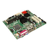
Global American 2807940 User Manual (170 pages)
Micro ATX Motherboard with LGA 775 Socket
Brand:
Global American
| Category:
Motherboard
| Size: 7 MB
Table of Contents
Packing List
5
Table of Contents
6
1 Introduction
17
Figure 1-1: 2807940 Uatx Motherboard
18
Figure 1-2: 2807940 Overview [Front View]
20
Technical Specifications
22
Overview
18
2807940 Features
19
2807940 Overview
19
2807940 Overview Photo
19
2807940 Peripheral Connectors and Jumpers
20
Table 1-1: Technical Specifications
23
2 Detailed Specifications
24
Dimensions
25
Board Dimensions
25
Figure 2-1: 2807940 Dimensions (MM)
25
Figure 2-2: External Interface Panel Dimensions (MM)
26
Figure 2-3: Data Flow Block Diagram
27
Compatible Processors
28
Supported Intel® Core™2 Quad (Yorkfield) Processors
28
Supported Processors Overview
28
Supported Intel® Core™2 Duo (Conroe) Processors
29
Supported Intel® Core™2 Duo (Wolfdale) Processors
29
Intel® Q35 Front Side Bus (FSB) Support
30
Intel® Q35 Northbridge Chipset
30
Supported Intel® Celeron® (Conroe) Processors
30
Data Flow
27
External Interface Panel Dimensions
26
Table 2-2: Supported Intel® Celeron® Processors
30
Figure 2-4: Front Side Bus (FSB)
31
Figure 2-5: DDR2 DIMM Sockets
31
Figure 2-6: VGA Connector
34
Figure 2-7: DMI Chip-To-Chip Connection
34
Figure 2-8: Audio Connectors
36
Intel® 82566DM Gigabit LAN Connect Device
37
Figure 2-9: Intel® 82566DM Gigabit LAN Connect Device
38
Intel ® ICH9DO Low Pin Count (LPC) Interface
38
Intel ® ICH9DO PCI Interface
39
Intel ® ICH9DO Pcie X4 Bus
39
Intel ® ICH9DO Real Time Clock
39
Intel ® ICH9DO SATA Controller
40
Figure 2-10: SATA Drive Connectors
41
Intel ICH9DO USB Controller Overview
41
Intel ® ICH9DO Serial Peripheral Interface (SPI) BIOS
41
Intel ® ICH9DO USB Controller
41
2807940 Pcie Bus Components
42
2807940 USB Implementation
42
Figure 2-11: Onboard USB Implementation
42
Pcie Bus Overview
42
Figure 2-12: Pcie X16 Slot
43
Pcie X16 Slot
43
Pcie X4 Slot
43
Figure 2-13: Pcie X4 Slot
44
Figure 2-14: Intel® 82573L Pcie Gbe Controller
44
Intel® 82573L Pcie Gbe Controller
44
Pci Bus Components
45
PCI Bus Overview
45
PCI Slots
45
Figure 2-15: PCI Slots
46
Lpc Bus Components
46
LPC Bus Overview
46
TPM Module
46
Figure 2-16: TPM Connector
47
Super I/O Chipset
47
Figure 2-17: ITE IT8712F Super I/O
48
Super I/O 16C550 Uarts
49
Super I/O Enhanced Hardware Monitor
49
Super I/O Floppy Disk Drive (FDD) Controller
49
Super I/O LPC Interface
49
Super I/O Fan Speed Controller
50
Super I/O GPIO Ports
50
Super I/O Infrared
50
Super I/O Keyboard/Mouse Controller
50
Super I/O Parallel Port
50
Ethernet Lan Controllers
51
Fintek F81216DG LPC Serial Port Chipset
51
Super I/O Watchdog Timer
51
Figure 2-18: LAN Connections
52
Environmental and Power Specifications
53
Operating Temperature and Temperature Control
53
System Monitoring
53
Power Consumption
54
Intel® Q35 Direct Media Interface (DMI)
34
Intel ® Ich9Do Southbridge Chipset
35
Intel ® ICH9DO Features
35
Intel ® ICH9DO Overview
35
Intel ® ICH9DO Ethernet Controller
36
Intel® ICH9DO High Definition Audio Implementation
36
Table 2-1: Supported Intel® Core™2 Duo (Conroe) Processors
30
Intel® Q35 Memory Controller
31
Intel® Q35 Pcie X16 Interface
32
Intel® Q35 Analog Display Capability
33
Intel® Q35 Graphics and Display Features
33
Table 2-3: Power Consumption
54
3 Unpacking
55
Anti-Static Precautions
56
Unpacking
56
Unpacking Precautions
56
Unpacking Checklist
57
Package Contents
57
Optional Items
58
Table 3-1: Package List Contents
58
Table 3-2: Package List Contents
58
4 Connector Pinouts
59
Figure 4-1: Connector and Jumper Locations
60
Table 4-1: Peripheral Interface Connectors
62
Internal Peripheral Connectors
63
ATX Power Connector
63
Peripheral Interface Connectors
60
2807940 Layout
60
Peripheral Interface Connectors
61
External Interface Panel Connectors
62
Table 4-2: Rear Panel Connectors
63
Figure 4-2: ATX Power Connector Pinout Locations
64
Table 4-4: Audio CD in Connector Pinouts
65
CPU Power Connector
66
Digital Input/Output (DIO) Connector
66
Table 4-3: ATX Power Connector Pinouts
64
Audio CD in Connector
65
Figure 4-3: Audio CD in Connector Pinouts (4-Pin)
65
Figure 4-6: +12V Fan Connector Location
68
Figure 4-7: +12V Fan Connector Location
69
Table 4-8: +12V Fan Connector Pinouts
69
Figure 4-8: 34-Pin FDD Connector Location
70
Figure 4-9: Front Audio Connector Location (10-Pin)
71
Front Audio Connector
71
Table 4-9: 34-Pin FDD Connector Pinouts
71
Front Panel Connector
72
Table 4-10: Front Audio Connector Pinouts
72
Figure 4-10: Front Panel Connector Pinout Locations (14-Pin)
73
Infrared Interface Connector
73
Table 4-11: Front Panel Connector Pinouts (14-Pin)
73
Figure 4-11: Infrared Connector Location
74
Pcie Power Connector
74
Table 4-12: Infrared Connector Pinouts
74
Figure 4-12: Pcie Power Connector Location
75
SATA Drive Connectors
75
Table 4-13: Pcie Power Connector Pinouts
75
Figure 4-13: SATA Drive Connector Locations
76
Table 4-14: SATA Drive Connector Pinouts
76
Figure 4-14: Serial Connector Location
77
Serial Port Connector (COM2, COM 3 and COM4)
77
Table 4-15: Serial Connector Pinouts
77
Figure 4-15: SPDIF Connector Location
78
SPDIF Connector
78
Table 4-16: SPDIF Connector Pinouts
78
Figure 4-16: TPM Connector Location
79
Table 4-17: TPM Connector Pinouts
79
Trusted Platform Module (TPM) Connector
79
Figure 4-17: USB Connector Locations
80
Table 4-18: USB Port Connector Pinouts
80
USB Connectors (Internal)
80
Audio Connectors
81
External Peripheral Interface Connector Panel
81
Figure 4-18: 2807940 External Peripheral Interface Connector
81
Figure 4-19: Audio Connector
82
Figure 4-20: PS/2 Pinouts
82
Keyboard/Mouse Connector
82
LAN and Dual USB Combo Connectors
83
Table 4-19: PS/2 Connector Pinouts
83
Table 4-20: LAN Pinouts
83
Table 4-22: USB Port Pinouts
84
Parallel Port, Serial Port and VGA Combo Connector
85
Table 4-5: CPU Power Connector Pinouts
66
Figure 4-4: CPU Power Connector Location
66
Figure 4-5: DIO Connector Location
67
Table 4-7: +12V Fan Connector Pinouts
68
Fan Connector, System (+12V, 3-Pin)
69
Floppy Disk Connector (34-Pin)
70
Table 4-6: DIO Connector Pinouts
67
Fan Connector, CPU (12V, 4-Pin)
68
Figure 4-21: RJ-45 Ethernet Connector
84
Table 4-21: RJ-45 Ethernet Connector Leds
84
Figure 4-22 Parallel Port Connector Pinout Locations
85
Table 4-23: Parallel Port Connector Pinouts
86
Table 4-24: RS-232 Serial Port (COM 1) Pinouts
86
Figure 4-23: COM1 Pinout Locations
86
Table 4-25: VGA Connector Pinouts
87
Figure 4-24: VGA Connector
87
5 Installation
88
Anti-Static Precautions
89
Installation Considerations
90
Installation Notices
90
Installation Checklist
91
Cpu, Cpu Cooling Kit and DIMM Installation
92
Socket LGA775 CPU Installation
93
Unpacking
92
Unpacking Precautions
92
Figure 5-1: Intel® LGA775 Socket
93
Figure 5-2: Remove the CPU Socket Protective Shield
94
Figure 5-3: Open the CPU Socket Load Plate
95
Figure 5-4: Insert the Socket LGA775 CPU
96
Figure 5-5: GAI 2107695 Cooling Kit
97
Figure 5-6: Securing the Heat Sink to the PCB Board
98
DIMM Installation Order
99
DIMM Purchasing Guidelines
99
Figure 5-7: DDR2 Channels
99
DIMM Installation Guidelines
100
Figure 5-8: Installing a DIMM
101
Clear CMOS Jumper
102
Table 5-1: Jumpers
102
COM Port Pin 9 Setting Jumpers
103
DIMM Installation
98
Jumper Settings
101
Step 1: Figure 5-9: Clear CMOS Jumper
103
Table 5-2: Clear CMOS Jumper Settings
103
Figure 5-10: COM Port Pin 9 Setting Jumper Locations
104
Table 5-4: COM Port Pin 9 Voltage Setting Jumper Settings
105
Airflow
106
Chassis Installation
106
Figure 5-11: COM Port Pin 9 Voltage Setting Jumper Locations
106
Dual RS-232 Cable Connection
107
Internal Peripheral Device Connections
107
Motherboard Installation
107
Peripheral Device Cables
107
Table 5-5: GAI Provided Cables
107
Figure 5-12: Dual RS-232 Cable Installation
108
SATA Drive Connection
108
Figure 5-13: SATA Drive Cable Connection
109
Figure 5-14: SATA Power Drive Connection
109
Figure 5-15: Dual USB Cable Connection
110
USB Cable (Dual Port)
110
Figure 5-16: Pcie X16 Installation
111
Pcie X16 Expansion Card Installation
111
Audio Connection
112
External Peripheral Interface Connection
112
Figure 5-17: Audio Connectors
113
LAN Connection (Single Connector)
113
Figure 5-18: LAN Connection
114
Parallel Device Connection
114
Figure 5-19: Parallel Device Connector
115
PS/2 Keyboard and Mouse Connection
115
Figure 5-20: PS/2 Keyboard/Mouse Connector
116
Serial Device Connection
116
Figure 5-21: Serial Device Connector
117
USB Device Connection
117
VGA Monitor Connection
118
Table 5-3: COM Port Pin 9 Setting Jumper Settings
104
COM Port Pin 9 Voltage Setting Jumpers
105
Socket LGA775 2107695 Cooling Kit Installation
96
Figure 5-22: USB Device Connection
118
Figure 5-23: VGA Connector
119
6 Intel Amt Configuration
120
Figure 8-1: Intel® Active Management Technology Status Dialog
121
Intel ® Amt Setup Procedure
121
Intel ® Management Engine Bios Extension
122
Figure 8-3: Change Intel® ME Password
123
Figure 8-2: Intel® Current ME Password
123
Figure 8-4: Verify New Password
124
Figure 8-6: Provision Model
124
Figure 8-5: Intel® AMT Configuration
124
Figure 8-7: Intel® AMT 3.0 Mode
125
Figure 8-8: Enterprise
125
Figure 8-9: Enable Network Interface
126
Using the Intel AMT Web Interface
127
Figure 8-10: Exit
127
Figure 8-11: Intel® AMT Web Address
128
Figure 8-12: Intel® AMT Web Login Dialog
128
Figure 8-13: Intel® AMT Web Interface
129
Aterminology
130
Bdio Interface
135
Dio Interface Introduction
136
Dio Connector Pinouts
136
B.1 Dio I Nterface I Ntroduction
136
B.2 Dio C Onnector P Inouts
136
Assembly Language Samples
137
Enable the DIO Input Function
137
Enable the DIO Output Function
137
Cwatchdog Timer
138
Daddress Mapping
141
Address Map
142
St Mb Memory Ddress Ap
142
D.1 Addres Map
142
D.2 1St MB Memory Addres Map
142
Irq Mapping Table
143
Dma Channel Assignments
143
D.4 Dma C Hannel a Ssignments
143
Ecompatibility
144
Compatible Operating Systems
145
Compatible Processors
145
Compatible Memory Modules
145
E.2 C Ompatible P Rocessors
145
E.3 C Ompatible M Emory M Odules
145
Fintel Matrix Storage Manager
147
Introduction
148
F.1 I Ntroduction
148
Precautions
148
Features and Benefits
149
Accessing the Intel Matrix Storage Manager
149
F.2 F Eatures and B Enefits
149
Raid Configuration
150
Creating a RAID Volume
150
Deleting a RAID Volume
155
Resetting a Disk to Non-RAID
157
Exiting the Matrix Storage Manager
159
Hazardous Materials Disclosure
161
Hazardous Material Disclosure Table for IPB Products Certified as Rohs Compliant under 2002/95/EC Without Mercury
162
Hindex
164
Advertisement
Advertisement
Related Products
Global American 2807930
Global American 2807960
Global American Mini-ITX 2807840
Global American 2807750
Global American 2807870
Global American 2807632
Global American 2807680
Global American 2807790
Global American 2807616
Global American 2807660 Series
Global American Categories
Motherboard
Single board computers
Computer Hardware
Controller
Desktop
More Global American Manuals
Login
Sign In
OR
Sign in with Facebook
Sign in with Google
Upload manual
Upload from disk
Upload from URL