Table of Contents
Advertisement
Quick Links
Advertisement
Table of Contents

Related Manuals for Global American 2808040


Summary of Contents for Global American 2808040
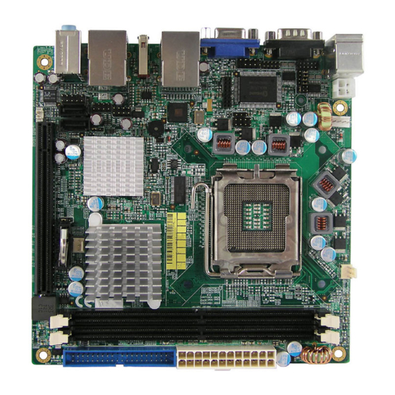
- Page 1 2808040 User’s Manual Mini-ITX Motherboard with Socket LGA 775 Version 1.0...
- Page 2 Copyrights This document is copyrighted and all rights are reserved. It does not allow any non authorization in copied, photocopied, translated or reproduced to any electronic or machine readable form in whole or in part without prior written consent from the manufacturer.
-
Page 3: Table Of Contents
Installing the CPU ............... 6 ATX Power Installation ............6 Installing the Memory ............7 Setting the Jumpers ............. 8 Connectors on 2808040............11 Appendix ............21 A. I/O Port Address Map ........... 21 B. Interrupt Request Lines (IRQ) ........22... - Page 4 This page is intentionally left blank.
-
Page 5: Introduction
Introduction Checklist Your 2808040 Core 2 Duo motherboard package should include the items listed below: • The 2808040 motherboard • This User’s manual • 1 x I/O shield • 1 x IDE cable • 1 x SATA cable • 1 CD containing the following: •... -
Page 6: Product Description
DVI display interface. LAN functionality is supported with a 10/100 Ethernet controller or with two Gigabit Ethernet controllers. 2808040 is expandable, with the use of an adaptor card, 1008097, to support 2 or 4 serial ports, or 1008098 to support TPM 1.2 security function. -
Page 7: Specifications
Specifications Form Factor Mini ITX (for performance desktop market) Processor Socket LGA775, Supports the Intel Core 2 Duo and Intel Core2 Quad processors, and Intel Celeron 400 (Conroe-L) Sequence processor. 800/1066/1333 MHz Chipset Intel Q35 Chipset: • Intel Q35 Graphic Memory Controller Hub (GMCH) •... -
Page 8: Board Dimensions
Board Dimensions... -
Page 9: Installations
Installations This section provides information on how to use the jumpers and connectors on the 2808040 in order to set up a workable system. The topics covered are: Installing the CPU ................ 6 ATX Power Installation ............... 6 Installing the Memory ..............7 Setting the Jumpers .............. -
Page 10: Installing The Cpu
Installing the CPU The 2808040 motherboard supports an LGA 775 processor socket for Intel® Core 2 Duo processors. The LGA 775 processor socket comes with a lever to secure the processor. Refer to the pictures below, from left to right, on how to place the processor into the CPU socket. -
Page 11: Installing The Memory
Installing the Memory The 2808040 motherboard supports four DDR2 memory sockets for a maximum total memory of 4GB in DDR memory type. It supports DDR2 667/800MHz. Basically, the system memory interface has the following features: Supports two 64-bit wide DDR data channels Available bandwidth up to 6.4GB/s (DDR2 800) for two-channel... -
Page 12: Setting The Jumpers
The following lists the connectors and their respective functions. Jumper Locations on 2808040.............. 9 JP7: Clear CMOS Contents ..............10 JP1, JP2, JP3: RS232/422/485 (COM2) Selection ......10... - Page 13 Jumper Locations on 2808040 Jumper Locations on 2808040............9 JP7: Clear CMOS Contents ............10 JP1, JP2, JP3: RS232/422/485 (COM2) Selection ....... 10...
- Page 14 JP7: Clear CMOS Contents Use JP7, a 3-pin header, to clear the CMOS contents. Note that the ATX-power connector should be disconnected from the motherboard before clearing CMOS. Setting Function Pin 1-2 Normal Short/Closed Pin 2-3 Clear CMOS Short/Closed JP1, JP2, JP3: RS232/422/485 (COM2) Selection COM1 is fixed for RS-232 use only.
-
Page 15: Connectors On 2808040
Connectors on 2808040 The connectors on 2808040 allows you to connect external devices such as keyboard, floppy disk drives, hard disk drives, printers, etc. The following table lists the connectors on 2808040 and their respective functions. ATX2: 24-pin ATX Power Connector ............. 13 ATX1: ATX 12V Power Connector .............. - Page 16 Connector Locations on 2808040 ATX2: 24-pin ATX Power Connector ....................13 ATX1: ATX 12V Power Connector ....................... 13 CPU_FAN1: CPU Fan Power Connector ....................13 SYS FAN1, 2: System Fan Power Connectors ..................13 CN4: PS/2 Keyboard and PS/2 Mouse Connectors ................14 CN2, J3: COM1/2 Serial Ports .......................
-
Page 17: Atx2: 24-Pin Atx Power Connector
ATX2: 24-pin ATX Power Connector Signal Name Pin # Pin # Signal Name 3.3V 3.3V -12V 3.3V Ground Ground PS-ON Ground Ground Ground Ground Ground Power good 5VSB +12V +12V Ground +3.3V ATX1: ATX 12V Power Connector This connector supplies the CPU operation voltage Pin # Signal Name Ground... -
Page 18: Cn4: Ps/2 Keyboard And Ps/2 Mouse Connectors
CN4: PS/2 Keyboard and PS/2 Mouse Connectors Keyboard Signal Pin # Mouse Signal Keyboard data Mouse data N.C. N.C. Mouse (top) Keyboard clock Mouse clock Keyboard (bottom) N.C. N.C. CN2, J3: COM1/2 Serial Ports CN2 (COM1) is a DB-9 connector, while J3 is a COM pin-header connector. -
Page 19: Cn1: Vga Crt Connector
CN1: VGA CRT Connector Signal Name Pin # Pin # Signal Name Green Blue N.C. N.C. DDCDATA HSYNC VSYNC DDCCLK CN6: Marvell 88E8053 PCI-express Gigabit LAN and USB2/3 Connector CN7: Intel 82562V 10/100 or Intel 82566DM GbE RJ-45 and USB0/1 Connector Note: 10/100 LAN for 2808040A;... -
Page 20: Cn9, Cn8: Sata Hdd Connectors
CN9, CN8: SATA HDD Connectors Pin # Signal Name Ground Ground Ground IDE1: Primary IDE Connectors Signal Name Pin # Pin # Signal Name Reset IDE Ground Host data 7 Host data 8 Host data 6 Host data 9 Host data 5 Host data 10 Host data 4 Host data 11... -
Page 21: J2: Digital I/O Connector (4 In, 4 Out)
J2: Digital I/O Connector (4 in, 4 out) This 10-pin digital I/O connector supports TTL levels and is used to control external devices requiring ON/OFF circuitry. Signal Name Pin # Pin # Signal Name Ground Out3 Out1 Out2 Out0 J4: For LPC I/F Adaptor Card Supports 1008097 with Fintek F81216, 2 or 4 serial ports J5: Audio Front Header Signal Name... -
Page 22: J9: Spdif Out Connector
J9: SPDIF Out Connector Pin # Signal Name SPDIF out Ground J10: System Function Connector ATX Power ON Switch: Pins 1 and 2 This 2-pin connector is an “ATX Power Supply On/Off Switch” on the system that connects to the power switch on the case. When pressed, the power switch will force the system to power on. -
Page 23: 1008097 Lpc Serial Ports Adapter (Option)
1008097 LPC Serial Ports Adapter (option) J1 J2: COM3/4/5/6 Serial Ports J1 - COM3/4 pin-header connector. PIN1~PIN10 COM3 PIN11~PIN20 COM4 J2 - COM5/6 pin-header connector. PIN1~PIN10 COM5 PIN11~PIN20 COM6 Signal Name Pin # Pin # Signal Name DCD, Data carrier detect DSR, Data set ready RXD, Receive data RTS, Request to send... - Page 24 J2: Digital I/O Connector (4 in, 4 out) This 10-pin digital I/O connector supports TTL levels and is used to control external devices requiring ON/OFF circuitry. Signal Name Pin # Pin # Signal Name Ground Out3 Out1 Out2 Out0 J4: For LPC I/F Adaptor Card Supports 1008097 with Fintek F81216, 2 or 4 serial ports J5: Audio Front Header Signal Name...
-
Page 25: Appendix
Appendix A. I/O Port Address Map Each peripheral device in the system is assigned a set of I/O port addresses that also becomes the identity of the device. The following table lists the I/O port addresses used. Address Device Description 000h - 01Fh DMA Controller #1 020h - 03Fh... -
Page 26: Interrupt Request Lines (Irq)
B. Interrupt Request Lines (IRQ) Peripheral devices use interrupt request lines to notify CPU for the service required. The following table shows the IRQ used by the devices on board. Level Function IRQ0 System Timer Output IRQ1 Keyboard IRQ2 Interrupt Cascade IRQ3 Serial Port #2 IRQ4... -
Page 27: C. Watchdog Timer Configuration 2
C. Watchdog Timer Configuration The WDT is used to generate a variety of output signals after a user programmable count. The WDT is suitable for use in the prevention of system lock-up, such as when software becomes trapped in a deadlock. Under these sorts of circumstances, the timer will count to zero and the selected outputs will be driven. - Page 28 printf("System will reset after %d seconds\n", bTime); EnableWDT(bTime); return 0; //======================================================================= void copyright(void) printf("\n======== Winbond 83627EHF Watch Timer Tester (AUTO DETECT) ========\n"\ " Usage : W627E_WD reset_time\n"\ " Ex : W627E_WD 3 => reset system after 3 second\n"\ " W627E_WD 0 => disable watch dog timer\n"); //======================================================================= void EnableWDT(int interval) unsigned char bBuf;...
- Page 29 //======================================================================= // THIS CODE AND INFORMATION IS PROVIDED "AS IS" WITHOUT WARRANTY OF ANY // KIND, EITHER EXPRESSED OR IMPLIED, INCLUDING BUT NOT LIMITED TO THE // IMPLIED WARRANTIES OF MERCHANTABILITY AND/OR FITNESS FOR A PARTICULAR // PURPOSE. //======================================================================= ==== #include "W627EHF.H"...
- Page 30 Lock_W627EHF(); //======================================================================= void Set_W627EHF_Reg( unsigned char REG, unsigned char DATA) Unlock_W627EHF(); outportb(W627EHF_INDEX_PORT, REG); outportb(W627EHF_DATA_PORT, DATA); Lock_W627EHF(); //======================================================================= unsigned char Get_W627EHF_Reg(unsigned char REG) unsigned char Result; Unlock_W627EHF(); outportb(W627EHF_INDEX_PORT, REG); Result = inportb(W627EHF_DATA_PORT); Lock_W627EHF(); return Result; //======================================================================= //======================================================================= // THIS CODE AND INFORMATION IS PROVIDED "AS IS" WITHOUT WARRANTY OF ANY // KIND, EITHER EXPRESSED OR IMPLIED, INCLUDING BUT NOT LIMITED TO THE // IMPLIED WARRANTIES OF MERCHANTABILITY AND/OR FITNESS FOR A PARTICULAR // PURPOSE.
- Page 31 APPENDIX File of the Main.cpp //===================================================================== // THIS CODE AND INFORMATION IS PROVIDED "AS IS" WITHOUT WARRANTY OF ANY // KIND, EITHER EXPRESSED OR IMPLIED, INCLUDING BUT NOT LIMITED TO THE // IMPLIED WARRANTIES OF MERCHANTABILITY AND/OR FITNESS FOR A PARTICULAR // PURPOSE.
- Page 32 We will do our best to support your products, projects and business. Address: Global American, Inc. 17 Hampshire Drive Hudson, NH 03051 Telephone: Toll Free U.S. Only (800) 833-8999 (603) 886-3900 FAX: (603) 886-4545 Website: http://www.globalamericaninc.com Support: Technical Support at Global American...
Need help?
Do you have a question about the 2808040 and is the answer not in the manual?
Questions and answers