Table of Contents
Advertisement
Available languages
Available languages
Quick Links
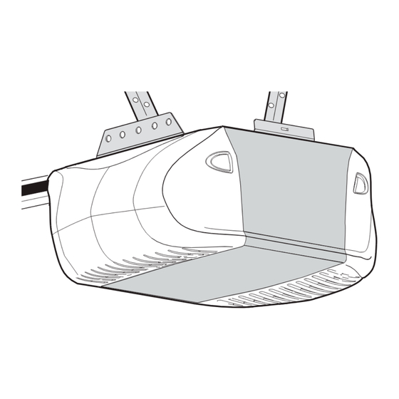
GARAGE DOOR OPENER
Model 3850C
For Residential Use Only
Owner's Manual
■
Please read this manual and the enclosed safety materials carefully!
■
Fasten the manual near the garage door after installation.
■
The door WILL NOT CLOSE unless the Protector System
aligned.
■
Periodic checks of the opener are required to ensure safe operation.
■
The model number label is located under the light lens on the left side panel of your
opener.
®
The Chamberlain Group, Inc.
845 Larch Avenue
Elmhurst, Illinois 60126-1196
www.liftmaster.com
®
is connected and properly
Advertisement
Chapters
Table of Contents

Related Manuals for Chamberlain Elie Security+ 3850C


Summary of Contents for Chamberlain Elie Security+ 3850C
- Page 1 The Chamberlain Group, Inc. 845 Larch Avenue Elmhurst, Illinois 60126-1196 www.liftmaster.com ® GARAGE DOOR OPENER Model 3850C For Residential Use Only Owner’s Manual ■ Please read this manual and the enclosed safety materials carefully! ■ Fasten the manual near the garage door after installation.
-
Page 2: Table Of Contents
TABLE OF CONTENTS Introduction Adjustment 23-25 Safety symbol and signal word review ....2 Program the travel limits ......23 Preparing your garage door . -
Page 3: Preparing Your Garage Door
Preparing your garage door WARNING Before you begin: To prevent possible SERIOUS INJURY or DEATH: • Disable locks. • ALWAYS call a trained door systems technician if garage CAUTION • Remove any ropes connected to garage door. door binds, sticks or is out of balance. An unbalanced garage door may not reverse when required. -
Page 4: Planning
Planning Identify the type and height of your garage door. Survey your garage area to see if any of the conditions below apply to your installation. Additional materials may be required. You may find it helpful to refer back to this page and the accompanying illustrations as you proceed with the installation of your opener. -
Page 5: Carton Inventory
Carton Inventory Your garage door opener is packaged in two cartons If anything is missing, carefully check the packing which contain the motor unit and all parts illustrated material. Parts may be stuck in the foam. Hardware for below. Accessories will depend on the model purchased. installation is also listed below. -
Page 6: Assembly
WARNING CAUTION ASSEMBLY STEP 1 Attach the Rail to the Motor Unit To avoid SERIOUS damage to opener, ONLY use bolts mounted in top of motor unit. To avoid installation difficulties, do not run the garage door opener until instructed to do so. •... -
Page 7: Attach The Belt Cap Retainer
WARNING ASSEMBLY STEP 3 Attach the Belt Cap Retainer To avoid possible SERIOUS INJURY to fingers from moving garage door opener: CAUTION • Position the belt cap retainer over the motor unit belt • ALWAYS keep hand clear of belt pulley while operating pulley so the three holes in cap align with the three opener. -
Page 8: Determine The Header Bracket Location
Unfinished INSTALLATION STEP 1 OPTIONAL Ceiling CEILING Determine the Header Bracket MOUNT Location HEADER BRACKET Header Wall WARNING WARNING Vertical Centerline of Garage Door To prevent possible SERIOUS INJURY or DEATH: • Header bracket MUST be RIGIDLY fastened to structural Structural CAUTION WARNING... -
Page 9: Install The Header Bracket
INSTALLATION STEP 2 Install the Header Bracket Wall Mounting Holes You can attach the header bracket either to the wall CEILING MOUNT ONLY The nail hole is for above the garage door, or to the ceiling. Follow the positioning only. You must use lag screws instructions which will work best for your particular to mount the header bracket. -
Page 10: Attach The Rail To The Header Bracket
INSTALLATION STEP 3 Attach the Rail to the Header Bracket • Position the opener on the garage floor below the header bracket. Use packing material as a protective Header Wall base. NOTE: If the door spring is in the way you’ll need help. -
Page 11: Position The Opener
WARNING CAUTION INSTALLATION STEP 4 Position the Opener To prevent damage to garage door, rest garage door opener rail on 2x4 placed on top section of door. Follow instructions which apply to your door type as illustrated. SECTIONAL DOOR OR ONE-PIECE DOOR WITH TRACK A 2x4 laid flat is convenient for setting an ideal door-to-rail distance. -
Page 12: Hang The Opener
WARNING INSTALLATION STEP 5 Hang the Opener To avoid possible SERIOUS INJURY from a falling garage door opener, fasten it SECURELY to structural supports of CAUTION Three representative installations are shown. Yours may the garage. Concrete anchors MUST be used if installing ANY be different. -
Page 13: Install The Control Console
WARNING WARNING CAUTION WARNING INSTALLATION STEP 6 Install the Control Console To prevent possible SERIOUS INJURY or DEATH from electrocution: Locate control console within sight of door, at a minimum • Disconnect ALL electric and battery power BEFORE height of 5' (1.5 m) where small children cannot reach, performing ANY service or maintenance. -
Page 14: Install The Battery Backup (Optional)
INSTALLATION STEP 7 Install the Battery Backup (Optional) Battery Cover Battery • Make sure motor unit is unplugged. • Using a Phillips head screwdriver, remove the battery cover on the motor unit. • Partially insert battery into motor unit with terminals facing out. -
Page 15: Attach The Emergency Release Rope And Handle
WARNING INSTALLATION STEP 9 Attach the Emergency Release Rope To prevent possible SERIOUS INJURY or DEATH from a and Handle falling garage door: CAUTION • If possible, use emergency release handle to disengage • Thread one end of the rope through the hole in the top trolley ONLY when garage door is CLOSED. -
Page 16: Install The Protector System (Safety Sensors)
WARNING INSTALLATION STEP 11 Install The Protector System ® Be sure power is not connected to the garage door opener (Safety Sensors) BEFORE installing the safety reversing sensor. CAUTION To prevent SERIOUS INJURY or DEATH from a closing The safety reversing sensor must be connected and garage door: aligned correctly before the garage door opener will •... - Page 17 INSTALLING THE BRACKETS Figure 1 Be sure power to the opener is disconnected. Install DOOR TRACK MOUNT (RIGHT SIDE) and align the brackets so the sensors will face each other across the garage door, with the beam no higher Door than 6"...
- Page 18 MOUNTING AND WIRING THE SAFETY REVERSING Figure 5 SENSORS Wing Nut • Slide a 1/4"-20x1/2" carriage bolt head into the slot on 1/4"-20 each sensor. Use wing nuts to fasten sensors to brackets, with lenses pointing toward each other across the door. Be sure the lens is not obstructed by Carriage Bolt a bracket extension (Figure 5).
-
Page 19: Fasten The Door Bracket
WARNING CAUTION INSTALLATION STEP 12 Fasten the Door Bracket Fiberglass, aluminum or lightweight steel garage doors WILL REQUIRE reinforcement BEFORE installation of door bracket. Follow instructions which apply to your door type as Contact your door manufacturer for reinforcement kit. illustrated below or on the following page. - Page 20 ONE-PIECE DOORS Please read and comply with the warnings and reinforcement instructions on the previous page. They apply to one-piece doors also. • Center the door bracket on the top of the door, in line with the header bracket as shown. Mark either the left and right, or the top and bottom holes.
-
Page 21: Connect Door Arm To Trolley
INSTALLATION STEP 13 Inner Trolley Connect Door Arm to Trolley Follow instructions which apply to your door type as Outer Trolley illustrated below and on the following page. SECTIONAL DOORS ONLY Clevis Pin 5/16"x1" Ring Make sure garage door is fully closed. Pull the Fastener emergency release handle to disconnect the outer trolley from the inner trolley. - Page 22 ALL ONE-PIECE DOORS Figure 4 1. Assemble the Door Arm: Door • Fasten the straight and curved door arm sections Ring Bracket Fastener together to the longest possible length (with a 2 or 3 Nuts Lock hole overlap). 5/16"-18 Washers •...
-
Page 23: Adjustment
WARNING ADJUSTMENT STEP 1 Program the Travel Limits Without a properly installed safety reversal system, persons Travel limits regulate the points at which the door (particularly small children) could be SERIOUSLY INJURED CAUTION will stop when moving up or down. Follow the steps or KILLED by a closing garage door. -
Page 24: Setting The Force
WARNING ADJUSTMENT STEP 2 Setting the Force Without a properly installed safety reversal system, persons (particularly small children) could be SERIOUSLY INJURED CAUTION The force setting button is located on the left panel or KILLED by a closing garage door. of the motor unit. -
Page 25: Test The Safety Reversal System
WARNING ADJUSTMENT STEP 3 Test the Safety Reversal System Without a properly installed safety reversal system, persons (particularly small children) could be SERIOUSLY INJURED CAUTION or KILLED by a closing garage door. TEST • Safety reversal system MUST be tested every month. •... -
Page 26: Operation
WARNING OPERATION IMPORTANT SAFETY INSTRUCTIONS WARNING To reduce the risk of SEVERE INJURY or DEATH: 1. READ AND FOLLOW ALL WARNINGS AND INSTRUCTIONS. 9. If one control (force or travel limits) is adjusted, the other control may also need adjustment. 2. -
Page 27: Using The Wall-Mounted Control Console
Using the Wall-Mounted Control (PROG) Learn Feature Console The control console is equipped with a Prog <LEARN> button to assist in learning remote controls to the unit. Press the Prog <LEARN> button once to initiate LEARN THE LCD MOTION DETECTING CONTROL CONSOLE mode and the display will show ‘Learn Remote Control - Press the push bar to Automatic Light... -
Page 28: To Open The Door Manually
To Open the Door Manually WARNING WARNING To prevent possible SERIOUS INJURY or DEATH from a falling garage door: CAUTION WARNING • If possible, use emergency release handle to disengage trolley ONLY when garage door is CLOSED. Weak or broken springs or unbalanced door could result in an open door falling rapidly and/or unexpectedly. -
Page 29: Battery Backup (Optional)
CAUTION WARNING cord from the electrical outlet. performing ANY service or maintenance. • Use only LiftMaster part # 485LMC for replacement • A solid orange LED indicates the battery is operating battery. on battery power. • Do NOT dispose of battery in fire. Battery may explode. -
Page 30: Care Of Your Garage Door Opener
Care of Your Garage Door Opener THE REMOTE CONTROL BATTERY MAINTENANCE SCHEDULE WARNING Once a Month To prevent possible SERIOUS INJURY or DEATH: • Manually operate door. If it is unbalanced or binding, • NEVER allow small children near batteries. CAUTION call a trained door systems technician. -
Page 31: Having A Problem (Troubleshooting)
Having a Problem (Troubleshooting) NOTE: Always unplug battery prior to troubleshooting. 1. My door will not close and the light bulbs blink on Bell Wire my motor unit: The safety reversing sensor must be connected and aligned correctly before the garage door opener will move in the down direction. -
Page 32: Diagnostic Chart
Bell Wire Diagnostics Located On Installed Motor Unit Safety Reversing Sensor “Learn” Button LED or Diagnostic Your garage door opener is programmed with self-diagnostic capabilities. The “Learn” button/diagnostic LED will flash a “Learn” Button Safety Reversing Sensor number of times then pause signifying it has found a potential issue. -
Page 33: Programming
PROGRAMMING NOTICE: If this Security ✚ ® garage door opener is operated with a non-rolling code remote control, the technical measure in the receiver of the garage door opener, which provides security against code-theft devices, will be circumvented. The owner of the copyright in the garage door opener does not authorize the purchaser or supplier of the non-rolling code remote control to circumvent that technical measure. -
Page 34: To Add, Reprogram Or Change A Keyless Entry Pin
To Add, Reprogram or Change a Keyless Entry PIN NOTE: Your new Keyless Entry must be programmed to operate your garage door opener. USING THE “LEARN” BUTTON USING THE LCD CONTROL CONSOLE 1. Press and release the “learn” button NOTE: This method requires two people if the Keyless on motor unit. -
Page 35: Repair Parts
REPAIR PARTS Rail Assembly Parts PART DESCRIPTION 4A1008 Master link kit 41B5424 Belt pulley bracket 41B3869-1 Complete trolley assembly 109B33 Trolley clip 2777BD One-piece rail 41A5434-11 Full belt assembly 41B4103 Tensioner assembly 83A11-2 Rail grease Installation Parts KEY PART DESCRIPTION 398LMC LCD motion detecting door control console 373LMC... -
Page 36: Motor Unit Assembly Parts
Motor Unit Assembly Parts PART PART DESCRIPTION DESCRIPTION 41C76 Belt cap and sprocket 41A6231 End panel with battery door and screw 41B4245 Line cord 41C190 Transformer and harness 41B4375-3 Terminal block with screws 41D504-4 Cover 41A6281 Wire harness kit Complete with: 108D79 Light lens Battery wires and plug... -
Page 37: Accessories
990LMC Surge Protector: The Garage Door Opener Surge Protector is designed to protect ® LiftMaster garage door openers against damage from lightning and power surges. -
Page 38: Notes
NOTES... -
Page 40: Warranty
6020 S. Country Club Road Tucson, Arizona 85706 For professional installation, parts and service, contact SERVICE INFORMATION your local LIFTMASTER/CHAMBERLAIN dealer. Look for TOLL FREE NUMBER: him in the Yellow Pages, or call our Service number for a 1-800-528-9131 list of dealers in your area. - Page 41 The Chamberlain Group, Inc. 845 Larch Avenue Elmhurst, Illinois 60126-1196 www.liftmaster.com ® OUVRE-PORTE DE GARAGE Modèle 3850C Pour résidences seulement Manuel d’instructions ■ Lire attentivement ce manuel ainsi que les consignes de sécurité! ■ Après la pose, accrocher ce manuel près de la porte de garage pour s’y reporter ultérieurement.
- Page 42 TABLE DES MATIÈRES Introduction Réglages 23-25 Revue des symboles de sécurité et des mots Réglage des courses .......23 de signalement .
-
Page 43: Préparation De Votre Porte De Garage
Préparation de votre porte de garage AVERTISSEMENT Avant de commencer : Pour prévenir d’éventuelles BLESSURES GRAVES ou LA MORT : • Désactiver les serrures. AVERTISSEMENT AVERTIS • TOUJOURS appeler un technicien formé en systèmes de porte si • Retirer toute corde raccordée à la porte de garage. la porte de garage force ou est déséquilibrée. -
Page 44: Planification
Planification Identifier le type et la hauteur de votre porte de garage. Examiner la région du garage pour noter si l’une des conditions ci-après s’applique à votre installation. Des matériaux supplémentaires peuvent être nécessaires. Il vous sera peut-être utile de vous reporter à... -
Page 45: Inventaire De La Boîte D'emballage
Inventaire de la boîte d’emballage Votre ouvre-porte de garage est emballé dans deux boîtes qui d’emballage. Les pièces peuvent être coincées dans la contiennent le moteur et toutes les pièces illustrées ci-après. mousse. Les ferrures de montage sont également indiquées ci- Les accessoires dépendront du modèle acheté. -
Page 46: Montage
AVERTISSEMENT ATTENTION MONTAGE - 1 OPÉRATION Fixation du rail au moteur Pour éviter des dommages SÉRIEUX à l’ouvre-porte, utiliser UNIQUEMENT les boulons et les fixations montés sur le dessus du Pour éviter les difficultés pendant la pose, ne faire moteur. fonctionner l'ouvre-porte de garage que lorsque cela est expressément indiqué. -
Page 47: Attachement Du Capuchon De Maintien De La Courroie
AVERTISSEMENT MONTAGE - 3E OPÉRATION Attachement du capuchon de Pour éviter d’éventuelles LÉSIONS GRAVES aux doigts par suite maintien de la courroie du mouvement de l’ouvre-porte : AVERTISSEMENT AVERT • TOUJOURS garder la main à l’ecart de la poulie à courroie lorsque •... -
Page 48: Déterminer L'emplacement Du Support De Linteau
POSE – 1 OPÉRATION Plafond MONTAGE DU non fini SUPPORT DE Déterminer l’emplacement du support de LINTEAU AU linteau PLANFOND EN OPTION AVERTISSEMENT Linteau Ligne du centre Pour prévenir d’éventuelles BLESSURES GRAVES ou LA MORT : vertical de la porte de garage TISSEMENT AVERTISSEMENT •... -
Page 49: Pose Du Support De Linteau
POSE – 2 OPÉRATION Pose du support de linteau Trous de fixation au mur Le support de linteau peut être fixé soit sur le mur, CEILING MOUNT ONLY Le trou du clou n'est prévu que au-dessus de la porte, soit au plafond. Suivre les instructions pour le positionnement qui répondent le mieux aux besoins particuliers. -
Page 50: Fixation Du Rail Sur Le Support De Linteau
POSE - 3 OPÉRATION Fixation du rail sur le support de linteau • Positionner l’ouvre-porte de garage sur le plancher, juste sous le support de linteau. Utiliser une des boîtes Linteau d’emballage pour le protéger. REMARQUE : Si le ressort de la porte gêne, il faudra demander de l’aide. -
Page 51: Positionnement De L'ouvre-Porte
AVERTISSEMENT ATTENTION POSE - 4 OPÉRATION Positionnement de l’ouvre-porte Pour prévenir les dommages à la porte de garage, faire reposer le rail de l’ouvre-porte de garage sur un 2 x 4 placé sur la section Suivre les instructions qui se rapportent à la porte de garage supérieure de la porte. -
Page 52: Accrochage De L'ouvre-Porte
AVERTISSEMENT POSE - 5 OPÉRATION Accrochage de l’ouvre-porte Pour éviter d’éventuelles BLESSURES GRAVES par suite de la chute d’un ouvre-porte de garage, fixer l’ouvre-porte SOLIDEMENT aux AVERTISSEMENT AVERT Les illustrations représentent trois poses types. La pose peut solives du garage. On DOIT utiliser des ancrages de béton si les toutefois être différente. -
Page 53: Pose De La Console De Commande
AVERTISSEMENT AVERTISSEMENT ATTENTION AVERTISSEMENT POSE - 6 OPÉRATION Pose de la console de commande Pour prévenir d’éventuelles BLESSURES GRAVES ou LA MORT par suite d’électrocution : Poser la commande murale dans un endroit où on pourra la • Débrancher l’alimentation batterie ET l’alimentation secteur AVANT voir de la porte, à... -
Page 54: Pose De Le Batterie De Secours (Optional)
POSE - 7 OPÉRATION Pose de la batterie de secours Couvercle de la batterie (Optional) Batterie • Vérifer que le moteur est débranché. • Enlever le couvercle de la batterie du moteur à l’aide d’un tournevis cruciforme. • Insérer partiellement la batterie dans le moteur, les bornes orientées vers l’extérieur. -
Page 55: Pose De La Corde Et De La Poignée De Déclenchement D'urgence
AVERTISSEMENT POSE - 9 OPÉRATION Pose de la corde et de la poignée de Pour prévenir d’éventuelles BLESSURES GRAVES ou LA MORT par déclenchement d’urgence suite de la chute d’une porte de garage : AVERTISSEMENT AVERTIS • Si possible, utiliser la poignée de déclenchement d’urgence pour •... -
Page 56: Pose Du Système Protector (Détectuer De Sésurité)
AVERTISSEMENT POSE - 11 OPÉRATION Pose du Système Protector ® S’assurer que l’ouvre-porte de garage est hors tension AVANT de (Détectuer de sésurité) poser le détecteur inverseur de sécurité. AVERTISSEMENT AVERTIS Pour prévenir des BLESSURES GRAVES ou LA MORT par suite Les détecteurs inverseurs de sécurité... - Page 57 POSE DES SUPPORTS MONTAGE SUR GUIDES DE PORTE (CÔTÉ DROIT) Figure 1 S’assurer que l’ouvre-porte est hors tension. Poser et aligner les supports de manière à ce que les détecteurs se fassent face l’un l’autre de part et d’autre de la Guide de porte porte du garage, le faisceau n’étant pas à...
- Page 58 MONTAGE ET CÂBLAGE DES DÉTECTEURS INVERSEURS Figure 5 DU SECURITIÉ Écrou à oreilles • Faire glisser un boulon à tête bombée et collet carré de 1/4 po-20 x 1/2 po dans la fente de chaque détecteur. Utiliser des écrous à oreilles pour fixer les détecteurs aux supports, avec les diffuseurs dirigés l’un vers l’autre de part et d’autre de la Boulon à...
-
Page 59: Fixation Du Support De La Porte
AVERTISSEMENT ATTENTION POSE - 12 OPÉRATION Fixation du support de la porte Les portes de garage en fibre de verre, en aluminium ou en acier léger ont BESOIN d’être renforcées AVANT la fixation du support de Suivre les instructions qui correspondent au type de porte, porte. - Page 60 PORTES RIGIDES Prière de lire et de suivre les avertissements et les instructions de renforcements à la page précédente. Ils s’appliquent également aux portes rigides. • Centrer le support de porte sur le dessus de la porte, en l’alignant avec le support de linteau, comme il est illustré. Repérer soit les trous de gauche et de droite, soit les trous du haut et du bas.
-
Page 61: Fixation De La Biellette Au Chariot
POSE - 13 OPÉRATION Chariot intérieur Fixation de la biellette au chariot Suivre uniquement les instructions se reportant à votre type de Chariot extérieur porte, comme illustré ci-dessous et à la page suivante. PORTE ARTICULÉE SEULEMENT Axe de chape de S’assurer que la porte du garage est complètement fermée. - Page 62 POUR TOUTES LES PORTES RIGIDES Figure 4 1. Assemblage des biellettes : Support • Assembler les biellettes droite et courbée à leur plus Anneau de la porte Écrous de d'arrêt grande longueur (2 ou 3 trous se chevauchant). 5/16 de po-18 •...
-
Page 63: Réglages
AVERTISSEMENT RÉGLAGES – 1ÈRE OPÉRATION Programmation des courses d’ouverture Sans un système d’inversion de sécurité bien installé, des et de fermeture personnes (plus particulièrement les petits enfants) pourraient être AVERTISSEMENT AVERTIS GRIÈVEMENT BLESSÉES ou TUÉES par une porte de garage qui se Le réglage de ces courses fixe les points où... -
Page 64: Réglage De La Force
AVERTISSEMENT RÉGLAGES – 2E OPÉRATION Réglage de la force Sans un système d’inversion de sécurité bien installé, des personnes (plus particulièrement les petits enfants) pourraient être AVERTISSEMENT AVERTIS Le bouton de réglage de la force est situé sur le panneau GRIÈVEMENT BLESSÉES ou TUÉES par une porte de garage qui se arrière du moteur. -
Page 65: Essai Du Système Protector (Détectuer De Sésurité)
AVERTISSEMENT RÉGLAGES - 3 OPÉRATION Essai du système d’inversion de sécurité Sans un système d’inversion de sécurité bien installé, des personnes (plus particulièrement les petits enfants) pourraient être AVERTISSEMENT AVERTIS GRIÈVEMENT BLESSÉES ou TUÉES par une porte de garage qui se ESSAI referme. -
Page 66: Fonctionnement
AVERTISSEMENT FONCTIONNEMENT IMPORTANTES CONSIGNES DE SÉCURITÉ AVERTISSEMENT AVERTISSEMENT Pour réduire le risque de BLESSURES GRAVES ou de MORT : 1. LIRE ET SUIVRE TOUS LES AVERTISSEMENTS ET INSTRUCTIONS. 9. Après avoir réglé une commande (force ou course), il peut être nécessaire de régler l’autre commande. -
Page 67: Utilisation De La Commande De Porte À Montage Murale
Utilisation de la commande de porte à Il est recommandé de désactiver le détecteur de mouvement montage mural en cas d'usage de l'éclairage de l'ouvre-porte comme éclairage de travail. Sinon, l'éclairage s'éteindra automatiquement si les travaux s'effectuent au-delà de la portée du détecteur. COMMANDE DE PORTE MURALE AVEC DÉTECTEUR DE MOUVEMENT (PROG) Fonction Learn... -
Page 68: Ouverture Manuelle De La Porte
Ouverture manuelle de la porte AVERTISSEMENT Pour prévenir d’éventuelles BLESSURES GRAVES ou LA MORT par suite de la chute d’une porte de garage : TISSEMENT AVERTISSEMENT • Si possible, utiliser la poignée de déclenchement d’urgence pour dégager le chariot UNIQUEMENT lorsque la porte de garage est FERMÉE. -
Page 69: Batterie De Secours (Optional)
AVERTISSEMENT TOUTE réparation ou maintenance. Pour tester la batterie, débrancher le cordon d'alimentation • N’utiliser que la pièce LiftMaster numéro 485LMC pour remplacer secteur du moteur. les batteries. • Le témoin DEL à lumière orange fixe indique que la batterie •... -
Page 70: Entretien De L'ouvre-Porte De Garage
Entretien de l’ouvre-porte de garage LA PILE DE LA TÉLÉCOMMANDE PÉRIODICITÉS D’ENTRETIEN AVERTISSEMENT Une fois par mois Pour prévenir d’éventuelles BLESSURES GRAVES ou LA MORT : • Faire fonctionner la porte à la main. Si elle est déséquilibrée • Ne JAMAIS laisser de petits enfants à proximité des piles. ou si elle force, appeler un technicien formé... -
Page 71: Défauts De Fonctionnement (Dépannage)
Défauts de fonctionnement (dépannage) REMARQUE : Toujours débrancher la batterie avant d’effectuer un dépannage. Fil de sonnerie 1. Ma porte ne se ferme pas et les ampoules de l’éclairage du moteur clignotent : Le détecteur inverseur de sécurité doit être raccordé et aligné correctement avant que l’ouvre- porte de garage n’entame la procédure de fermeture. -
Page 72: Fiche Diagnostique
Fil de sonnerie Diagnostic situé sur le moteur Montage du détecteur inverseur du sécurité « Learn » Bouton Des fonctions d’autodiagnostic ont été programmées dans votre Voyant LED ouvre-porte de garage. Le bouton « learn » ou le voyant LED de ou LED diagnostic diagnostic émettra un certain nombre d’éclairs avant de faire une... -
Page 73: Programmation
PROGRAMMATION REMARQUE : Si cet ouvre-porte de garage Security ✚ ® est utilisé avec une télécommande émettrice à code fixe, le dispositif technique que contient le récepteur de l’ouvre-porte et qui procure une protection contre les vols de code, se trouvera contourné. Le détenteur des droits d’auteur de cet ouvre-porte de garage n’autorise pas l’acheteur ni le fournisseur de la télécommande émettrice à... -
Page 74: Pour Ajouter, Reprogrammer Ou Modifier Un Nip D'entrée Sans Clé
Pour ajouter, reprogrammer ou modifier un NIP d’entrée sans clé REMARQUE : Votre nouvelle entrée sans clé doit être programmée de manière à faire fonctionner votre ouvre-porte de garage. UTILISATION DU BOUTON « LEARN » UTILISATION DE LA CONSOLE DE COMMANDE DE ACL REMARQUE : Cette méthode nécessite deux personnes si le pavé... -
Page 75: Pièces De Recharge
PIÈCES DE RECHANGE Pièces d’assemblage du rail N° DE RÉF. PIÈCE DÉSIGNATION 4A1008 Maillon de raccord 41A5424 Support de poulie de courroie 41B3869-1 Chariot complet 109B33 Pince de chariot 2777BD Rail rigide 41A5434-11 Ensemble courroie complet 41B4103 Ensemble tendeur 83A11-2 Graisse à... -
Page 76: Pièces D'assemblage Du Moteur
Pièces d’assemblage du moteur N° DE N° DE RÉF. PIÈCE DÉSIGNATION RÉF. PIÈCE DÉSIGNATION 41C76 Capuchon de retenue 41A6231 Panneau d’extrémité avec de la courroie couvercle de batterie et vis 41B4245 Cordon électrique 41C190 Transformateur avec harnais 41B4375-3 Bornier avec vis 41D504-4 Couvercle 41A6281... -
Page 77: Accessoires
990LMC Protecteur de montée : Le protecteur de montée subite d'ouvreur de porte de garage estconçu pour protéger des ouvreurs de porte de garage de LiftMaster ® contre des dommages contre des montées subites de foudre et de puissance. -
Page 78: Remarques
REMARQUES... - Page 79 REMARQUES...
-
Page 80: Garantie
1-800-528-9131 GARANTIE LIMITÉE DE 5 ANS SUR L'OUVRE-PORTE DE GARAGE LIFTMASTER GARANTIE LIMITÉE À VIE SUR LE MOTEUR ET COURROIE The Chamberlain Group, Inc. (le « Vendeur ») garantit au premier acheteur au détail de ce produit, pour la résidence dans laquelle ce produit est originalement installé, que ce produit est exempt de vice de matériaux et/ou de main-d’œuvre pour une période de cinq ans à...
Need help?
Do you have a question about the Elie Security+ 3850C and is the answer not in the manual?
Questions and answers