Table of Contents
Advertisement
Quick Links
Copyright
Copyright © 2012 MiTAC International Corporation. All rights reserved. No part of
this manual may be reproduced or translated without prior written consent from
MiTAC International Corporation.
Trademark
All registered and unregistered trademarks and company names contained in this
manual are property of their respective owners including, but not limited to the
following.
®
TYAN
is a trademark of MiTAC International Corporation.
®
Intel
is a trademark of Intel
AMI, AMI BIOS are trademarks of AMI Technologies.
®
Microsoft
, Windows
®
Winbond
is a trademark of Winbond Electronics Corporation.
Notice
Information contained in this document is furnished by MiTAC International
Corporation and has been reviewed for accuracy and reliability prior to printing.
MiTAC assumes no liability whatsoever, and disclaims any express or implied
warranty, relating to sale and/or use of TYAN
warranties relating to fitness for a particular purpose or merchantability. MiTAC
retains the right to make changes to product descriptions and/or specifications at
any time, without notice. In no event will MiTAC be held liable for any direct or
indirect, incidental or consequential damage, loss of use, loss of data or other
malady resulting from errors or inaccuracies of information contained in this
document.
S5515
Version 1.1a
®
Corporation.
®
are trademarks of Microsoft Corporation.
http://www.tyan.com
®
products including liability or
1
Advertisement
Table of Contents

Related Manuals for TYAN S5515


Summary of Contents for TYAN S5515
- Page 1 Corporation and has been reviewed for accuracy and reliability prior to printing. MiTAC assumes no liability whatsoever, and disclaims any express or implied ® warranty, relating to sale and/or use of TYAN products including liability or warranties relating to fitness for a particular purpose or merchantability. MiTAC retains the right to make changes to product descriptions and/or specifications at any time, without notice.
- Page 2 http://www.tyan.com...
-
Page 3: Table Of Contents
3.5 Boot ....................67 3.6 Security.................... 70 3.7 Save & Exit ..................71 Chapter 4: Diagnostics................73 4.1 Flash Utility ..................73 4.2 AMIBIOS Post Code (Aptio) ............74 Appendix: Fan and Temp Sensors............81 Glossary..................... 83 Technical Support ..................89 http://www.tyan.com... -
Page 4: Before You Begin
6 x SATA Cable 1 x COM dual-port Bracket Cable 1 x USB dual-port Bracket Cable 1 x IO shielding 1 x S5515 User’s manual 1 x S5515 Quick reference guide ® 1 x TYAN Driver CD IMPORTANT NOTE: Sales sample may not come with the accessory listed above. -
Page 5: Chapter 1: Instruction
Leveraging advanced technology from ® Intel , the S5515 is capable of offering scalable 32 and 64-bit computing, high- bandwidth memory design, and lightning-fast PCI-E bus implementation. The S5515 not only empowers you in today’s demanding IT environment but also offers a smooth path for future application upgradeability. - Page 6 / User-configurable H/W monitoring / Auto-configurable of hard disk types Form Factor Micro ATX Physical Dimension Board Dimension 9.6"x9.6" (243.8x243.8mm) Operating OS supported list Please visit our Web site for the latest update. System FCC (DoC) Class B Regulation CE (DoC) http://www.tyan.com...
-
Page 7: Software Specifications
(1) TYAN installation CD Package Contains I/O Shield (1) I/O Shield SATA (6) SATA signal cables Cable Others (1) COM dual-port bracket cable 1.3 Software Specifications ® For OS (operation system) support, please check with TYAN support for latest information. http://www.tyan.com... - Page 8 NOTE http://www.tyan.com...
-
Page 9: Chapter 2: Board Installation
(5) Inspect the board for damage. The following pages include details on how to install your motherboard into your chassis, as well as installing the processor, memory, disk drives and cables. NOTE: Do not apply power to the board if it has been damaged. http://www.tyan.com... -
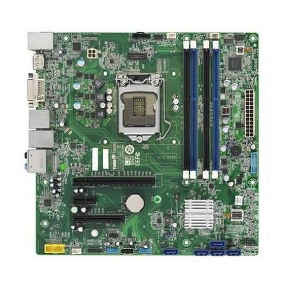
Page 10: Board Image
2.1 Board Image S5515 This picture is representative of the latest board revision available at the time of publishing. The board you receive may not look exactly like the above picture. http://www.tyan.com... -
Page 11: Block Diagram
2.2 Block Diagram S5515 Block Diagram http://www.tyan.com... -
Page 12: Board Parts, Jumpers And Connectors
The board you receive may not look exactly like the above diagram. But for the DIMM number please refer to the above placement for memory installation. For the latest board revision, please visit our web site at http://www.tyan.com. http://www.tyan.com... - Page 13 ME Header SPDIF Header Speaker Header FP_USB1/2 Front USB Connector LED1 ID LED AUX_Power_LED1 Aux Power LED 3-pin Header USB_A Type-A USB Connector Jumper Legend OPEN - Jumper OFF Without jumper cover CLOSED - Jumper ON With jumper cover http://www.tyan.com...
- Page 14 CPU Fan COM1/COM4 COM2/COM3 U_SPI1 Front Fan Rear Fan http://www.tyan.com...
- Page 15 Signal Signal 3VSB SLP_S3 SLP_S4 3VSB SLP_A SLP_SUSB VCC3 J2: ID LED Switch Header Signal FP IDLED Switch U_SPI1: BIOS SPI ROM Header Signal Signal SPI CS 3.3V Standby SPI MISO SPI HOLD# SPI SP# SPI Clock SPI MOSI http://www.tyan.com...
- Page 16 INT SPKR FCFH1 F AUDIO1 http://www.tyan.com...
- Page 17 J76: 82583 LAN Activity LED Header Signal Signal VCC3 82583_LED_ACT- J82: 82579 LAN Activity LED Header Signal Signal VCC3 LAN1_LINK_ACTIVITY- F_AUDIO1: Front Audio Connector Signal Signal FP_MIC_L AGND FP_MIC_R AUDIO_Detect AUO_HPOUT_R AUO_SENSE_MIC FIO_SENSE KEY-Pin FP_MIC_L AUO_SENSE_HP INT_SPKR: Internal Speaker Header Signal Signal INT_SPKR- INT_SPKR+ http://www.tyan.com...
- Page 18 LED1 FP USB 1/2 SATA 2/3/4/5 http://www.tyan.com...
- Page 19 J13: SPDIF Header Signal SPDIF_OUT KEY-Pin SATA_2/SATA_3/SATA_4/SATA_5: SATA2.0 Connector Connects to the Serial ATA ready SATA TX DP drives via the Serial ATA cable. SATA TX DN NOTE: SATA_5 can support SATA RX DN SATA DOM Device. SATA RX DP http://www.tyan.com...
- Page 20 AUX Power LED1 SATA 6G 0/1 http://www.tyan.com...
- Page 21 2. Use jumper cap to close Pin_1 and Pin_2 for seconds to Clear CMOS. 3. Put jumper cap back to Pin_2 and Pin_3 (default setting). Normal (Default) 4. Reconnect power & power on system. J6: ME Header Pin 1-2 Closed: Fresh ME Firmware Pin 2-3 Closed: Normal (Default) http://www.tyan.com...
-
Page 22: Installing The Processor And Heat Sink
NOTE: MiTAC TYAN is not liable for damage as a result of operating an unsupported configuration. Processor Installation (SNB-DT Socket H2 LGA1155 for Intel CPU) Follow the steps below to install the processors and heat sinks. - Page 23 Place the CPU in the CPU socket and make sure that the gold arrow is located in the right direction with two notches properly aligned. Close the socket cover and press the CPU socket lever down to lock the CPU in place. http://www.tyan.com...
- Page 24 The following diagram illustrates how to install the heatsink for the SNB-DT Socket H2 LGA1155. Place the heat sink on top of the CPU and push the 4 latches in a diagonal pattern to lock it in place. Connect the fan cable to complete the installation. http://www.tyan.com...
-
Page 25: Thermal Interface Material
CPU lid (applying too much will actually reduce the cooling). NOTE: Always check with the manufacturer of the heat sink & processor to ensure that the thermal interface material is compatible with the processor and meets the manufacturer’s warranty requirements. http://www.tyan.com... -
Page 26: Tips On Installing Motherboard In Chassis
Some chassis include plastic studs instead of metal. Although the plastic studs are usable, MiTAC recommends using metal studs with screws that will fasten the motherboard more securely in place. http://www.tyan.com... - Page 27 Below is a chart detailing what the most common motherboard studs look like and how they should be installed. http://www.tyan.com...
-
Page 28: Installing The Memory
2.7 Installing the Memory Before installing memory, ensure that the memory you have is compatible with the motherboard and processor. Check the TYAN Web site at http://www.tyan.com details of the type of memory recommended for your motherboard. The following diagram shows common types of DDR3 memory modules. - Page 29 UDIMM can support up to 8GB sized DIMM’s Maximum of 16GB per channel SR and DR UDDR3 module support only SR and DR 1.5v Memory MAX speed of 1333/1600* MHz in a dual channel configuration IVB CPU can support up to 1600MHz. http://www.tyan.com...
- Page 30 DIMM Location http://www.tyan.com...
- Page 31 Memory Installation Procedure Follow these instructions to install memory modules into the S5515. Press the locking levers in the direction shown in the following illustration. Align the memory module with the socket. The memory module is keyed to fit only one way in the socket.
-
Page 32: Attaching Drive Cables
2.8 Attaching Drive Cables Attaching Serial ATA Cables S5515 is equipped with six (6) Serial ATA (SATA) channel. Connections for the drives are very simple. There is no need to set Master/Slave jumpers on SATA drives. If you are in need of SATA/SAS cables or power adapters please contact your place of purchase. -
Page 33: Installing Add-In Cards
Doing so allows air to circulate within the chassis more easily, thus improving cooling for all installed devices. NOTE: You must always unplug the power connector to the motherboard before performing system hardware changes to avoid damaging the board or expansion device. http://www.tyan.com... -
Page 34: Connecting External Devices
10/100/1000 Mbps LAN Link/Activity LED Scheme Left LED Right LED Link Green Amber 10 Mbps Active Blinking Green Green Link Green Amber 100 Mbps Active Blinking Green Green Link Green Amber 1000 Mbps Active Blinking Green Green No Link http://www.tyan.com... -
Page 35: Installing The Power Supply
2.11 Installing the Power Supply There are two (2) power connectors on your S5515 motherboard. The S5515 supports EPS 12V power supply. ATX24P_1: 24-Pin EPS 12V Power Main Connector Signal Signal +3.3V +3.3V +3.3V -12V PS ON# Power OK Reserve... -
Page 36: Finishing Up
In the rare circumstance that you have experienced difficulty, you can find help by asking your vendor for assistance. If they are not available for assistance, please find setup information and documentation online at our website or by calling your vendor’s support line. http://www.tyan.com... -
Page 37: Chapter 3: Bios Setup
The table below shows how to navigate in the setup program using the keyboard. Function Left/Right Arrow Keys Change from one menu to the next Up/Down Arrow Keys Move between selections Enter Open highlighted section PgUp/PgDn Keys Change pages Change options Exit http://www.tyan.com... - Page 38 The following pages provide the details of BIOS menu. Please be noticed that the BIOS menu are continually changing due to the BIOS updating. The BIOS menu provided are the most updated ones when this manual is written. Please visit TYAN’s website at http://www.tyan.com for the information of BIOS updating. http://www.tyan.com...
-
Page 39: Main Menu
Choose the system default BIOS Vendor American Megatrends language Core Version x.x.x.x Compliancy UEFI x.x BIOS Version TYAN S5515 BIOS Vx.xx Build Date and Time MM/DD/YYYY xx:xx:xx System Language [English] →←: Select screen ↑↓: Select item System Date [xxx MM/DD/YYYY]... -
Page 40: Advanced Menu
USB Configuration Parameters. Info Report Configuration Info Report Configuration. Super IO Configuration System Super IO Chip Parameters. Hardware Health Configuration Hardware Health Configuration Parameters. Serial Port Console Redirection Serial Port Console Redirection. CPU PPM Configuration CPU PPM Configuration Parameters. http://www.tyan.com... - Page 41 Onboard Device Configuration Onboard Device Configuration. http://www.tyan.com...
- Page 42 Both S1 and S3 available for OS to choose from / S1 only (CPU Stop Clock) / S3 only (Suspend to RAM) / Suspend Disabled Lock Legacy Resources Enable or disable Lock Legacy Resources. Disabled / Enabled S3 Video Repost Enable or disable S3 Video Repost. Disabled / Enabled http://www.tyan.com...
- Page 43 Enable or disable System wake on alarm event. When enabled, System will wake on the hr:min:sec specified. Disabled / Enabled Wake System on Dynamic Time Enable or disable System wake on alarm event. When enabled, System will wake on the current time + Increase minute(s). Disabled / Enabled http://www.tyan.com...
- Page 44 When disabled only one thread per enabled core is enabled. Enabled / Disabled Active Processor Cores Number of cores to enable in each processor package. All / 1 / 2 / 3 Limit CPUID Maximum Disabled for Windows XP. Disabled / Enabled http://www.tyan.com...
- Page 45 When enabled, a VMM can utilize the additional hardware capabilities provided by Vanderpool Technology. Enabled / Disabled Hardware Prefetcher To turn on/off the Mid Level Cache (L2) streamer prefetcher. Enabled / Disabled Adjacent Cache Line Prefetch To turn on/off prefetching of adjacent cache lines. Enabled / Disabled http://www.tyan.com...
- Page 46 SATA Mode Selection Determine how SATA Controller(s) operate. AHCI / IDE / RAID Serial ATA Port 0/1/2/3/4/5 Read only. Port 0/1/2/3/4/5 Enable or disable SATA Port. Enabled / Disabled Hot Plug Designate this port as Hot Pluggable. Enabled / Disabled http://www.tyan.com...
- Page 47 The time-out value for Control, Bulk, and Interrupt transfers. 20 sec / 10 sec / 5 sec / 1 sec Device reset time-out USB mass storage device Start Unit command time-out. 20 sec / 10 sec / 30 sec / 40 sec http://www.tyan.com...
- Page 48 Maximum time the device will take before it properly reports itself to the Host Controller. “AUTO” uses default value: for a Root port it is 100 ms, for a Hub port the delay is taken from Hub descriptor. Auto / Manual http://www.tyan.com...
- Page 49 Post Report Wait Time: 0 ~ 10 Seconds 5 / 0 / 1 / 2 / 3 / 4 / 6 / 7 / 8 / 9 / 10 / Until Press ESC Summery Screen Summery Screen Support Enabled/Disabled. Disabled / Enabled http://www.tyan.com...
- Page 50 / IO=3F8h, IRQ=3, 4, 5, 6, 7, 9, 10, 11, 12; / IO=2F8h; IRQ=3, 4, 5, 6, 7, 9, 10, 11, 12; / IO=3E8h, IRQ=3, 4, 5, 6, 7, 9, 10, 11, 12; / IO=2E8h, IRQ=3, 4, 5, 6, 7, 9, 10, 11, 12; http://www.tyan.com...
- Page 51 PCI-E Ambient PCH Area DIMM Ambient →←: Select screen CPU_Fan ↑↓: Select item Front_Fan Enter: Select Rear_Fan +/-: Change Opt. VCORE F1: General Help VBAT F2: Previous Values 3.3V F3: Optimized Defaults F4: Save & Exit ESC: Exit Read only. http://www.tyan.com...
- Page 52 Console redirection enable or disable. Disabled / Enabled Console Redirection Settings The settings specify how the host computer and the remote computer (which the user is using) will exchange data. Both computers should have the same or compatible settings. http://www.tyan.com...
- Page 53 1’s in the data bits is odd. Mark: parity bit is always 1. Space: parity bit is always 0. Mark and Space parity do not allow for error detection. None / Even / Odd / Mark / Space http://www.tyan.com...
- Page 54 Disabled / Enabled Legacy OS Redirection Resolution On Legacy OS, the Number of Rows and Columns supported redirection. 80x24 / 80x25 Putty KeyPad Select Function Key and KeyPad on Putty. VT100 / LINUX / XTERMR6 / SCO / ESCN / VT400 http://www.tyan.com...
- Page 55 ‘start’ signal can be sent to restart the flow. Hardware flow control uses two wires to send start/stop signal. None / Hardware RTS/CTS / Software Xon/Xoff Data Bits / Parity / Stop Bits Read only. http://www.tyan.com...
- Page 56 Enable/Disable CPU C3 (ACPI C2) report to OS. Enabled / Disabled CPU C6 Report Enable/Disable CPU C6 (ACPI C3) report to OS. Enabled / Disabled CPU C7 Report Enable/Disable CPU C7 (ACPI C3) report to OS. Enabled / Disabled http://www.tyan.com...
- Page 57 F3: Optimized Defaults F4: Save & Exit ESC: Exit LAN1 Option ROM Enabled/Disabled the LAN Option ROM in the Chipset. Disabled / PXE / iSCSI LAN2 Option ROM Enabled/Disabled the LAN Option ROM in the Chipset. Disabled / PXE http://www.tyan.com...
-
Page 58: Chipset Menu
↑↓: Select item Enter: Select +/-: Change Opt. F1: General Help F2: Previous Values F3: Optimized Defaults F4: Save & Exit ESC: Exit South Bridge South Bridge Parameters. North Bridge North Bridge Parameters. WatchDog Timer Configuration WatchDog Timer Configuration. http://www.tyan.com... - Page 59 Select AC power state when power is re-applied after a power failure. Power Off / Power On / Last State Chassis Intrusion Detection Enabled: When a chassis open event is detected, the BIOS will display the event. Disabled / Enabled http://www.tyan.com...
- Page 60 Memory Configuration →←: Select screen ↑↓: Select item Enter: Select +/-: Change Opt. F1: General Help F2: Previous Values F3: Optimized Defaults F4: Save & Exit ESC: Exit VT-d Check to enable the VT-d function on MCH. Enabled / Disabled http://www.tyan.com...
- Page 61 Select DVMT 5.0 Pre-Allocated (Fixed) Graphics Memory size used by the Internal Graphics Device. 64M / 32M / 96M / 128M / 160M / 192M / 224M / 256M / 288M / 320M / 352M / 384M / 416M / 448M / 480M / 512M / 1024M http://www.tyan.com...
- Page 62 1280x1024 LVDS / 1400x1050 (RB) LVDS1 / 1400x1050 LVDS2 / 1600x1200 LVDS / 1366x768 LVDS / 1680x1050 LVDS / 1920x1200 LVDS / 1440x900 LVDS / 1600x900 LVDS / 1024x768 LVDS2 / 1280x800 LVDS / 1920x1080 LVDS / 2048x1536 LVDS http://www.tyan.com...
- Page 63 DMI Extended Synch Control Enable DMI Extended Synchronization. Disabled / Enabled DMI Gen 2 Enable or disable DMI Gen 2. Auto means Disabled for IVB A0 MB/DT and IVB B0 MB. Enabled for other CPUs. Auto / Disabled / Enabled http://www.tyan.com...
- Page 64 Control ASPM support for the PEG: Device 1 Function 0. This has no effect if PEG is not the currently active device. Auto / Disabled / ASPM L0s / ASPM L1 / ASPM L0sL1 Enable PEG Enable or disable the PEG. Auto / Enabled / Disabled http://www.tyan.com...
- Page 65 Select DIMM timing profile that should be used. Default DIMM profile / Custom Profile / XMP Profile 1 / XMP Profile 2 Memory Frequency Limiter Maximum Memory Frequency Selection in Mhz. Auto / 1067 / 1333 / 1600 / 1867 / 2133 / 2400 / 2667 http://www.tyan.com...
- Page 66 Disabled / POST / OS / PowerON NOTE: When Watch Dog Mode is set to [Disabled], the following item will not appear. Watch Dog Timer Watch Dog Timer Help. 2 MINS / 4 MINS / 6 MINS / 8 MINS / 10 MINS http://www.tyan.com...
-
Page 67: Boot
UPON REQUEST – GA20 can be disabled using BIOS services. ALWAYS – do not allow disabling GA20; this option is useful when any RT code is executed above 1MB. Upon Request / Always Option ROM Messages Select display mode for Option ROM. Force BIOS / Keep Current http://www.tyan.com... - Page 68 BIOS reaction on INT19 trapping by Option ROM: IMMEDIATE – execute the trap right away; POSTPONED – execute the trap during the legacy boot. Immediate / Postponed Endless Boot Enable or disable Endless Boot. Disabled / Enabled Boot Option #1 Set the system boot order. UEFI: Built-in EFI Shell / Disabled http://www.tyan.com...
- Page 69 Control the execution of UEFI and Legacy Storage OpROM. Legacy only / Do not launch / UEFI only Launch Video OpROM policy Control the execution of UEFI and Legacy Video OpROM. Legacy only / Do not launch / UEFI only http://www.tyan.com...
-
Page 70: Security
Confirm New Password window will pop out to ask for confirmation. User Password Set user password in the Create New Password window. After you key in the password, the Confirm New Password window will pop out to ask for confirmation. http://www.tyan.com... -
Page 71: Save & Exit
Discard changes done so far to any of the setup options. Restore Defaults Restore/Load Default values for all the setup options. Save as User Defaults Save the changes done so far as User Defaults. Restore User Defaults Restore the User Defaults to all the setup options. http://www.tyan.com... - Page 72 NOTE http://www.tyan.com...
-
Page 73: Chapter 4: Diagnostics
BIOS flash failure, you must contact your dealer for a replacement BIOS. There are no exceptions. TYAN does not have a policy for replacing BIOS chips directly with end users. In no event will TYAN be held responsible for damages done by the end user. -
Page 74: Amibios Post Code (Aptio)
South Bridge initialization before microcode loading 0x05 OEM initialization before microcode loading 0x06 Microcode loading 0x07 AP initialization after microcode loading 0x08 North Bridge initialization after microcode loading 0x09 South Bridge initialization after microcode loading 0x0A OEM initialization after microcode loading 0x0B Cache initialization http://www.tyan.com... - Page 75 CPU post-memory initialization is started. 0x33 CPU post-memory initialization. Cache initialization 0x34 CPU post-memory initialization. Application Processor(s) (AP) initialization 0x35 CPU post-memory initialization. Boot Strap Processor (BSP) selection 0x36 CPU post-memory initialization. System Management Mode(SMM) initialization 0x37 Post-Memory North Bridge initialization is started. http://www.tyan.com...
- Page 76 Reserved for future AMI progress codes S3 Resume Error Codes 0xE8 S3 Resume failed 0xE9 S3 Resume PPI not found 0xEA S3 Resume Boot Script error 0xEB S3 OS wake error 0xEC – 0xEF Reserved for future AMI error codes http://www.tyan.com...
- Page 77 CPU DXE initialization (CPU module specific) 0x67 CPU DXE initialization (CPU module specific) 0x68 PCI host bridge initialization 0x69 North Bridge DXE initialization is started. 0x6A North Bridge DXE SMM initialization is started. 0x6B North Bridge DXE initialization (North Bridge module specific) http://www.tyan.com...
- Page 78 USB initialization is started. 0x9B USB Reset 0x9C USB Detect 0x9D USB Enable 0x9E -0x9F Reserved for future AMI codes 0xA0 IDE initialization is started 0xA1 IDE Reset 0xA2 IDE Detect 0xA3 IDE Enable 0xA4 SCSI initialization is started. http://www.tyan.com...
- Page 79 No Console Output Devices are found. 0xD7 No Console Input Devices are found. 0xD8 Invalid password 0xD9 Error loading Boot Option (LoadImage returned error) 0xDA Boot Option is failed (StartImage returned error). 0xDB Flash update is failed. 0xDC Reset protocol is not available. http://www.tyan.com...
- Page 80 System is waking up from the S3 sleep state. 0x40 System is waking up from the S4 sleep state. 0xAC System has transitioned into ACPI mode. Interrupt controller is in APIC mode. 0xAA System has transitioned into ACPI mode. Interrupt controller is in APIC mode. http://www.tyan.com...
-
Page 81: Appendix: Fan And Temp Sensors
This section aims to help readers identify the locations of some specific FAN and Temp Sensors on the motherboard. A table of BIOS Temp sensor name explanation is also included for readers’ reference. NOTE: The red dot indicates the sensor. http://www.tyan.com... - Page 82 Temperature of the CPU MOS Area PCI-E Ambient Temperature of the PCI-E Area PCH Area Temperature of the PCH Area DIMM Ambient Temperature of the DIMM Area CPU_Fan Fan Speed of CPU_Fan Front_Fan Fan Speed of Front_Fan Rear_Fan Fan Speed of Rear_Fan http://www.tyan.com...
-
Page 83: Glossary
(reading to or writing from a disk drive a single time is much faster than doing so repeatedly) there is the possibility of losing your data should the system crash. Information in a buffer is temporarily stored, not permanently saved. http://www.tyan.com... - Page 84 (like soundcards or keyboards) to access the main memory without involving the CPU. This frees up CPU resources for other tasks. As with IRQs, it is vital that you do not double up devices on a single line. Plug-n-Play devices will take care of this for you. http://www.tyan.com...
- Page 85 EEPROM (Electrically Erasable Programmable ROM): also called Flash BIOS, it is a ROM chip which can, unlike normal ROM, be updated. This allows you to keep ® up with changes in the BIOS programs without having to buy a new chip. TYAN ’s BIOS updates can be found at http://www.tyan.com...
- Page 86 PXE (Preboot Execution Environment): one of four components that together make up the Wired for Management 2.0 baseline specification. PXE was designed to define a standard set of preboot protocol services within a client with the goal of allowing networked-based booting to boot using industry standard protocols. http://www.tyan.com...
- Page 87 NVIDIA s (graphics communications processing units) and NVIDIA MCPs (media and processors). application Depending on the , NVIDIA SLI can deliver as much as two times the performance of a single GPU configuration. http://www.tyan.com...
- Page 88 CPUs without damaging the sensitive CPU pins. The CPU is lightly placed in an open ZIF socket, and a lever is pulled down. This shifts the processor over and down, guiding it into the board and locking it into place. http://www.tyan.com...
-
Page 89: Technical Support
(which can have expensive consequences). If these options are not available for you then TYAN can help. Besides designing innovative and quality products for over a decade, TYAN has continuously offered customers service beyond their expectations. - Page 90 (RMA) number. The RMA number Should be prominently displayed on the outside of the shipping carton and the package should be mailed prepaid. TYAN will pay to have the board shipped back to you. Notice for the USA Compliance Information Statement (Declaration of...
Need help?
Do you have a question about the S5515 and is the answer not in the manual?
Questions and answers