Table of Contents
Advertisement
Copyright
Copyright © 2016 MiTAC International Corporation. All rights reserved. No part of
this manual may be reproduced or translated without prior written consent from
MiTAC International Corporation.
Trademark
All registered and unregistered trademarks and company names contained in this
manual are property of their respective owners including, but not limited to the
following.
®
TYAN
is a trademark of MiTAC International Corporation.
®
Intel
is a trademark of Intel
AMI, AMI BIOS are trademarks of AMI Technologies.
®
Microsoft
, Windows
®
Winbond
is a trademark of Winbond Electronics Corporation.
Notice
Information contained in this document is furnished by MiTAC International
Corporation and has been reviewed for accuracy and reliability prior to printing.
MiTAC assumes no liability whatsoever, and disclaims any express or implied
warranty, relating to sale and/or use of TYAN
warranties relating to fitness for a particular purpose or merchantability. MiTAC
retains the right to make changes to product descriptions and/or specifications at
any time, without notice. In no event will MiTAC be held liable for any direct or
indirect, incidental or consequential damage, loss of use, loss of data or other
malady resulting from errors or inaccuracies of information contained in this
document.
S5547
Version 1.0
®
Corporation.
®
are trademarks of Microsoft Corporation.
http://www.tyan.com
®
products including liability or
1
Advertisement
Table of Contents

Subscribe to Our Youtube Channel
Related Manuals for TYAN S5547


Summary of Contents for TYAN S5547
-
Page 1: S5547
Corporation and has been reviewed for accuracy and reliability prior to printing. MiTAC assumes no liability whatsoever, and disclaims any express or implied ® warranty, relating to sale and/or use of TYAN products including liability or warranties relating to fitness for a particular purpose or merchantability. MiTAC retains the right to make changes to product descriptions and/or specifications at any time, without notice. -
Page 2: Table Of Contents
Contents S5547 ......................1 Before you begin… ..................3 Chapter 1: Instruction ................4 1.1 Congratulations ................. 4 1.2 Hardware Specifications ..............4 Chapter 2: Board Installation ..............6 2.1 Board Image ..................7 2.2 Block Diagram ................... 8 2.3 Motherboard Mechanical Drawing ............. 9 2.4 Board Parts, Jumpers and Connectors ........... -
Page 3: Before You Begin
Before you begin… Check the box contents! The retail motherboard package should contain the following: 1 x S5547 Motherboard 1 x Rear IO shielding 1 x S5547 Quick Installation Guide ® 1 x TYAN Driver CD 2 x SATA Single Cable IMPORTANT NOTE: Sales sample may not come with the accessory listed above. -
Page 4: Chapter 1: Instruction
S5547 is capable of offering scalable 32 and 64-bit computing, high-bandwidth memory design, and lightning-fast PCI-E bus implementation. The S5547 not only empowers you in today‟s demanding IT environment but also offers a smooth path for future application upgradeability. All of these rich feature sets provide the S5547 with the power and flexibility to meet demanding requirements for today‟s IT environments. - Page 5 - 40° C ~ 70° C (-40° F ~ 158° F) Temp. Environment In/Non-operating 90%, non-condensing at 35° C Humidity RoHS RoHS 6/6 Compliant Yes Motherboard (1) S5547 Motherboard Package Manual (1) Web User's manual / (1) Quick Installation Guide Contains Installation CD (1) TYAN installation CD http://www.tyan.com...
-
Page 6: Chapter 2: Board Installation
Caution! To avoid damaging the motherboard and associated components, do not use torque force greater than 7kgf/cm (6.09 lb/in) on each mounting screw for motherboard installation. Do not apply power to the board if it has been damaged. http://www.tyan.com... -
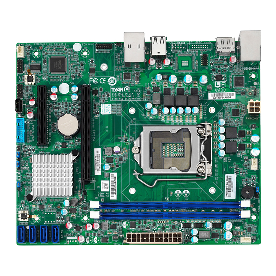
Page 7: Board Image
2.1 Board Image S5547G2NR This picture is representative of the latest board revision available at the time of publishing. The board you receive may not look exactly like the above picture. http://www.tyan.com... -
Page 8: Block Diagram
2.2 Block Diagram S5547 Block Diagram http://www.tyan.com... -
Page 9: Motherboard Mechanical Drawing
2.3 Motherboard Mechanical Drawing http://www.tyan.com... -
Page 10: Board Parts, Jumpers And Connectors
The board you receive may not look exactly like the above diagram. The DIMM slot numbers shown above can be used as a reference when reviewing the DIMM population guidelines shown later in the manual. For the latest board revision, please visit our web site at http://www.tyan.com. http://www.tyan.com... -
Page 11: Motherboard Components
ME DISABLE Jumper (J15) c Recovery Jumper (J19) b Clear CMOS Jumper (J17) d Buzzer Jumper (J20) Slots A PCIE X16 slot (PCIE_X16_SLOT1) B PCIE X8 slot (PCIE_X8_SLOT1, signal up to X4) C DIMM_A0 (J8C1) D DIMM_B0 (J8C2) http://www.tyan.com... - Page 12 J16 (CPU FAN) / J30 (Front FAN) / J2 (Rear FAN): 4-pin FAN Connector Signal VCC12 TACHOMETER Use this header to connect the cooling fan to your motherboard to keep the system stable and reliable. Note: A 4-pin fan is required for fan support 4pin Control http://www.tyan.com...
- Page 13 USB_DP USB_DN USB3_TX_P USB3_TX_N USB3_RX_P USB3_RX_N 5V_AUX SATA0(J28)/SATA1(J27)/SATA2(J26)/SATA3(J25) : 7-pin vertical SATA3.0 Connector(Blue) Name TYPE SATA TX DP SATA TX DN SATA RX DN SATA RX DP Connects to the Serial ATA ready drives via the Serial ATA cable. http://www.tyan.com...
- Page 14 DBG_HD1: TYAN Module Header (Port80 Debug Header) Signal Signal P3V3 FRAME_N LAD0 LAD1 PLT_RST_N LAD2 LAD3 CLK_24M DBG_SERIRQ DBG_PRES_N VCC3_AUX TPM_ADDR_MB PCH_TPM_PP_EN J10: COM Header Signal Signal SOUT J13: Vertical (Type A) USB2.0 Connectors Signal 5V_AUX USB_DN USB_DP J8: LPC Header...
- Page 15 5. Reconnect power connectors to the motherboard and power on Clear CMOS system. J19: Recovery Jumper Pin 1-2 Closed: Normal Mode (Default) Pin 2-3 Closed: Configure Recovery Remove Cap: J20: BUZZER Jumper Pin 3-4 Closed: Disable Pin 2-3 Closed: Disable Pin 3-4 Closed: Enable (Default) http://www.tyan.com...
-
Page 16: Installing The Processor And Heatsink
2.5 Installing the Processor and Heatsink The types of processors supported by the S5547 are listed in the 1.2 Hardware Specifications section on page 4. Check our website at http://www.tyan.com ® the latest list of validated Intel processors for this specific motherboard. - Page 17 Remove the CPU protection cap. Install the processor and make sure the gold arrow is located in the right direction with two notches properly aligned. Close the CPU socket cover. Press the socket lever down to lock the CPU in place. http://www.tyan.com...
- Page 18 The following diagram illustrates how to install the heat sink for the SNB_H4 (LGA1151) socket. Apply the thermal grease. Place the heat sink on top of the CPU and push the 4 latches in a diagonal pattern to lock it in place. http://www.tyan.com...
- Page 19 Secure the heat sink screws. Connect the fan cable to complete the installation. http://www.tyan.com...
-
Page 20: Tips On Installing Motherboard In Chassis
Be especially careful to look for extra stand-offs. If there are any stand-offs present that are not aligned with a mounting hole on the motherboard, it will likely short components on the back of the motherboard when installed. This will cause malfunction and/or damage to your motherboard. http://www.tyan.com... - Page 21 Some chassis include plastic studs instead of metal. Although the plastic studs are usable, MiTAC recommends using metal studs with screws that will fasten the motherboard more securely in place. Below is a chart detailing what the most common motherboard studs look like and how they should be installed. http://www.tyan.com...
-
Page 22: Installing The Memory
2.7 Installing the Memory Before installing memory, ensure that the memory you have is compatible with the motherboard and processor. Check the TYAN Web site at http://www.tyan.com details of the type of memory recommended for your motherboard. Supports up to 32GB of un-buffered ECC... - Page 23 1.√ indicates a populated DIMM slot. 2. Use paired memory installation for max performance. 3. Populate the same DIMM type in each channel, specifically - Use the same DIMM size - Use the same # of ranks per DIMM http://www.tyan.com...
-
Page 24: Memory Installation Procedure
Memory Installation Procedure Follow these instructions to install memory modules into the S5547. Unlock a DIMM socket by Press the retaining clip outwardly in the following illustration. Align the memory module with the socket,such that the DIMM NOTCH match the KEY SLOT on the socket. -
Page 25: Attaching Drive Cables
The following illustrates how to make a SATA Cable connection. If you are in need of SATA/SAS cables or power adapters please contact your local sales representative. 1. SATA drive cable connection 2. SATA drive power connection 3. SATA cable motherboard connector 4. SATA drive power adapter http://www.tyan.com... -
Page 26: Installing Add-In Cards
Doing so allows air to circulate within the chassis more easily, thus improving cooling for all installed devices. NOTE: You must always unplug the power connector from the motherboard before performing system hardware changes to avoid damaging the board or expansion device. http://www.tyan.com... -
Page 27: Connecting External Devices
The chart below illustrates the different LED states. 10/100/1000 Mbps LAN Link/Activity LED Scheme Left LED Right LED Link Green 10 Mbps Active Blinking Green Link Green Green 100 Mbps Active Blinking Green Green Link Green Amber 1000 Mbps Active Blinking Green Amber No Link http://www.tyan.com... -
Page 28: Installing The Power Supply
2.11 Installing the Power Supply There are Two (2) power connectors on your S5547 motherboard. The S5547 supports EPS 12V power supply. J24: 24-Pin Power Connector Signal Signal V3P3 V3P3 V3P3 -12V PS_ON# PWROK 5VSB +12V +12V V3P3 PWRCONN1: ATX 4-pin Power Connector... -
Page 29: Chapter 3: Bios Setup
Select the previous or next value/setting of the field <ESC> Exit current menu <F1> General help <F2> Previous values <F3> Load the Optimal default configuration values of the menu <F4> Save and exit <PgUp> / <PgDn> Move cursor to next/previous page http://www.tyan.com... - Page 30 BIOS menus are continually changing due to continual BIOS updates over the product lifespan of the motherboard. The BIOS menus provided are current as of the date when this manual was written. Please visit TYAN‟s website at http://www.tyan.com for information on BIOS updates available for this specific motherboard.
-
Page 31: Main Menu
It displays BIOS related information. Memory Information This displays the total memory size. Access Level Read only. System Date Adjust the system date. MM (Months): DD (Days): YYYY (Years) System Time Adjust the system clock. HH (24 hours format): MM (Minutes): SS (Seconds) http://www.tyan.com... -
Page 32: Advanced Menu
This section facilitates configuring advanced BIOS options for your system. Trusted Computing Trusted Computing settings. ACPI Settings System ACPI Parameters. WatchDog Timer Configuration Watchdog Configuration PCH-FW Configuration Configure Management Engine Technology Parameters Super IO Configuration System Super IO Chip Parameters Hardware Health Configuration Monitor hardware Status http://www.tyan.com... - Page 33 SATA Device Options Settings PCI Subsystem Settings PCI, PCI-X and PCI Express Settings CSM Configuration CSM Configuration: Enable/Disable Option ROM execution settings, etc NVMe Configuration MVMe Device Options Settings USB Configuration USB Configuration Parameters. Onboard Device Configuration Onboard Device and Function Configuration. http://www.tyan.com...
- Page 34 NOTE: Your Computer will reboot during restart in order to change State of the Device. Enabled / Disabled Pending operation Schedule an operation for the security device. NOTE: Your Computer will reboot during restart in order to change state of Security Device. None / TPM Clear http://www.tyan.com...
- Page 35 SHA256 PCR Bank Enable or Disable SHA256 POR Bank Enabled / Disabled Pending operation Schedule an operation for the security Device. NOTE: Your Computer will reboot during restart in order to change State of Security Device. None / TPM Clear http://www.tyan.com...
- Page 36 TPM 1.2 will restrict support to TPM 1.2 devices. TPM 2.0 will restrict support to TPM 2.0 devices, Auto will support both with the default set 2.0 to TPM 2. 0 devices if not found, TPM 1. 2 devices will be enumerated. TPM 1.2 / TPM 2.0 / Auto http://www.tyan.com...
- Page 37 3.3.3 ACPI Settings ACPI Sleep State Select the highest ACPI Sleep State the system will enter when the SUSPEND button is pressed. S3 (Suspend to RAM) / Suspend Disabled http://www.tyan.com...
- Page 38 The duration of enabling Watchdog Timer. When Watching time-out occurs, System will reboot immediately. Disabled / POST / OS / PowerON NOTE: Watch Dog Timer will appear when Watch Dog Mode is not set to [Disabled]. Watch Dog Timer Select 2/4/6/8/10 minutes for Watchdog time intervals http://www.tyan.com...
- Page 39 ME Unconfig on RTC Clear State Disabling this option will cause ME not to unconfigure on RTC clear Enabled / Disabled ME State Set ME to soft Temporary Disabled Enabled / Disabled Firmware Update Configuration Configure Management Engine Technology Parameters http://www.tyan.com...
- Page 40 3.3.5.1 Firmware Update Configuration Me FW Image Re-Flash Enable /Disable Me FW Image Re-Flash function. Enabled / Disabled http://www.tyan.com...
- Page 41 3.3.6 Super IO Configuration Super IO Chip Read only. http://www.tyan.com...
- Page 42 / IO=3F8h, IRQ=3, 4, 5, 6, 7, 9, 10, 11, 12; / IO=2F8h; IRQ=3, 4, 5, 6, 7, 9, 10, 11, 12; / IO=3E8h, IRQ=3, 4, 5, 6, 7, 9, 10, 11, 12; / IO=2E8h, IRQ=3, 4, 5, 6, 7, 9, 10, 11, 12; http://www.tyan.com...
- Page 43 Auto Fan Control must be set to [Enabled] PWM Minimal Duty Cycle menu will appear. Auto Fan Control Default setting is [Disabled]. PWM Minimal Duty Cycle PWM Minima Duty Cycle 30% Duty Cycle / 45% Duty Cycle / 60% Duty Cycle http://www.tyan.com...
- Page 44 3.3.7.1 Sensor Data Register Monitoring When you enter the Sensor Data Register Monitoring submenu, you will see the following dialog window pop out. NOTE 1: SDR can not be modified. Read only. http://www.tyan.com...
- Page 45 When set to [Fixed Time] , wake up hour Select 0-23 for example enter 8 for 3am and 15 for 3pm wake up minute Select 0-59 wake up second Select 0-59 When set to [Dynamic Time] , Wake up minute increase http://www.tyan.com...
- Page 46 The settings specify how the host computer and the remote computer (which the user is using) will exchange data. Both computers should have the same or compatible settings. NOTE: Console Redirection Settings menu only appear when Console Redirection was set to [Enabled]. http://www.tyan.com...
- Page 47 1‟s in the data bits is odd. Mark: parity bit is always 1. Space: parity bit is always 0. Mark and Space parity do not allow for error detection. None / Even / Odd / Mark / Space http://www.tyan.com...
- Page 48 VT100 / LINUX / XTERMR6 / SCO / ESCN / VT400 Redirection After BIOS POST The settings specify if BootLoader is selected than Legacy console redirection is disabled before booting to Legacy OS. Default value is always enable means Legacy. Always Enable / Bootloader http://www.tyan.com...
- Page 49 VT-UTF8 / VT100 / VT100+ / ANSI Bits per Second Select serial port transmission speed. The speed must be matched on the other side. Long or noisy lines may require lower speeds. 115200 / 9600 / 19200 / 57600 http://www.tyan.com...
- Page 50 „start‟ signal can be sent to restart the flow. Hardware flow control uses two wires to send start/stop signal. None / Hardware RTS/CTS / Software Xon/Xoff Data Bits / Parity / Stop Bits Read only. http://www.tyan.com...
- Page 51 And Disabled for other OS(OS not optimized for Hyper-threading Technology). When Disabled only one thread per enabled core is enabled. Enabled / Disabled Active Processor Cores Number of cores to enable in each processor package All / 1 / 2 / 3 http://www.tyan.com...
- Page 52 Enable/Disable Intel(R) speed shift Technology support. Enabling will express the CPPC v2 interface to allow for hardware controlled P-states. Enabled Disabled Intel(R) SpeedStep(tm) Allow more than two frequency ranges to be supported. Enabled Disabled Turbo Mode Turbo mode. Enabled Disabled http://www.tyan.com...
- Page 53 Package C State Limit Package C State limit C0 / C1 / C2 / C3 / C6 / C7 / C7s/ C8 / Auto SW Guard Extensions (SGX) Enable/ Disable Software Guard Extensions(SGX) Disabled / Enabled / Software Controlled http://www.tyan.com...
- Page 54 3.3.11 Intel Ready Mode Technology Intel Ready Mode Technology Enable / Disable Ready Mode support based on Windows Aways-mode. Only on DT/AIO Enabled / Disabled http://www.tyan.com...
- Page 55 AHCI Serial ATA Port 0/1/2/3 Hot Plug Enable/Disable SATA Ports Hot Pluggable. Disabled / Enabled SATA Device Type Indentify the SATA port is connected to Solid State Drive or Hard Disk Drive Hard Disk Drive / Solid State Drive http://www.tyan.com...
- Page 56 3.3.13 PCI Subsystem Above 4G Decoding Enables or Disables 64bit capable Devices to be decoded in Above 4G Address Space (Only if System supports 64 bit PCI Decoding). Enable / Disabled http://www.tyan.com...
- Page 57 Immediate / Postponed Boot option filter This option controls Legacy UEFI ROMs priority UEFI and Legacy / Legacy only / UEFI only Network Controls the execution of UEFI and Legacy PXE OpROM Do not launch / UEFI / legacy http://www.tyan.com...
- Page 58 Do not launch / UEFI / legacy Video Controls the execution of UEFI and Legacy Video OpROM Do not launch / UEFI / legacy Other PCI devices Determines OpRom execution policy for devices other than Network, Storage, or Video legacy / UEFI http://www.tyan.com...
- Page 59 3.3.15 NVMe Configuration Only Read http://www.tyan.com...
- Page 60 Maximum time the device will take before it properly reports itself to the Host Controller. AUTO uses default value: for a Root port it is 100 ms, for a Hub port the delay is taken from Hub descriptor. Auto / Manual http://www.tyan.com...
- Page 61 LAN2 OPROM Enable or Disable onboard LAN2 OPROM Disabled / PXE NOTE: The ISCSI function is only supported in LAN#1. Chassis Intrusion Detect ENABLED: When a chassis open event is detected, the BIOS will record the event. Disabled / Enabled http://www.tyan.com...
-
Page 62: Chipset Menu
3.4 Chipset Menu North Bridge System Agent(SA) parameters. South Bridge PCH parameters. http://www.tyan.com... - Page 63 3.4.1 North Bridge Configuration VT-d VT-d capability Enabled / Disabled Graphics Configuration Graphics Configuration Memory Configuration Memory Configuration Parameters http://www.tyan.com...
- Page 64 Primary Display Select which of IGFX/PEG/PCI Graphics device should be Primary Display Or select SG for switchable Gfx. Auto / IGFX / PEG / PCIE Internal Graphics Keep IGFX enabled based on the setup options. Auto / Enable Disabled http://www.tyan.com...
- Page 65 3.4.1.2 Memory Configuration Maximum Memory Frequency Maximum Memory Frequency selection in Mhz Auto / 1866 / 2133 http://www.tyan.com...
- Page 66 ME is on at Sx state. Enabled / Disabled SLP_LAN# Low on DC Power Enable/Disable SLP_LAN# Low on DC Power. Enabled / Disabled High Precision Timer Enable or Disable the High Precision Event Timer. Enabled / Disabled http://www.tyan.com...
- Page 67 HD Audio Configuration Submenu HD Audio Configuration Control Detection of the HD-Audio device. Disabled= HDA will be unconditionally disabled Enabled = HDA will be unconditionally enabled Auto= HDA will b enabled if present, disabled otherwise. Disabled / Enabled / Auto http://www.tyan.com...
-
Page 68: Security
3.5 Security Administrator Password Set Administrator Password. User Password Set User Password. Secure Boot Customizable Secure Boot settings http://www.tyan.com... - Page 69 2. CSM function is disabled Enabled / Disabled Secure Boot Mode Secure Boot mode selector. ‟Custom‟ mode enables users to change Image execution policy and manage secure boot keys. Standard / Custom Key Management Enables experienced users to modify Secure Boot variables http://www.tyan.com...
- Page 70 Set New Key 1. Public Key Certificate in: a) EFI_SIGNATURE_LIST b) EFI_CERT_X509 (DER encoded) c) EFI_CERT_RSA2048 (bin) d) EFI_CERT_SHA256 (bin) 2. Authenticated UEFI Variable Key: Vendor, Custom, Mixed, Test (*) modified from Setup menu Set New Key Append Key http://www.tyan.com...
- Page 71 Enroll factory Defaults or load the keys from a file with: 1. Public Key Certificate in: a) EFI_SIGNATURE_LIST b) EFI_CERT_X509 (DER encoded) c) EFI_CERT_RSA2048 (bin) d) EFI_CERT_SHA256 (bin) 2. Authenticated UEFI Variable Key: Vendor, Custom, Mixed, Test (*) modified from Setup menu Set New Key Append Key http://www.tyan.com...
- Page 72 Enroll factory Defaults or load the keys from a file with: 1. Public Key Certificate in: a) EFI_SIGNATURE_LIST b) EFI_CERT_X509 (DER encoded) c) EFI_CERT_RSA2048 (bin) d) EFI_CERT_SHA256 (bin) 2. Authenticated UEFI Variable Key: Vendor, Custom, Mixed, Test (*) modified from Setup menu Set New Key Append Key http://www.tyan.com...
-
Page 73: Boot
Enable or disable Quiet Boot option. Disabled / Enabled Boot Option Priorities Boot Option #1/#2/#3/#4/#5 Sets the system boot order. Device Name / Disabled Wait For “ESC” If Error Wait for “ESC” key to be pressed if error occurs. Disabled / Enabled http://www.tyan.com... - Page 74 Disabled / Enabled 3.6.1 Add New Boot Option Configuration Add boot option Specify name for new boot option Path for boot option Enter the path to the boot option in the format fsx:\path\filename.efi Create Creates the newly formed boot option http://www.tyan.com...
- Page 75 3.6.2 Delete Boot Option Configuration Delete Boot Option Sets the system boot order. Device Name / Select one to Delete http://www.tyan.com...
-
Page 76: Save & Exit
Reset system setup without saving any changes. Save Changes Save changes done so far to any of the setup options. Discard Changes Discard changes done so far to any of the setup options. Restore Defaults Restore/Load Default values for all the setup options. http://www.tyan.com... - Page 77 Save as User Defaults Save the changes done so far as User Defaults. Restore User Defaults Restore the User Defaults to all the setup options. Boot Override Device Name http://www.tyan.com...
-
Page 78: Chapter 4: Diagnostics
BIOS flash failure, you must contact your dealer for a replacement BIOS. There are no exceptions. TYAN does not have a policy for replacing BIOS chips directly with end users. In no event will TYAN be held responsible for damages done by the end user. -
Page 79: Amibios Post Code (Aptio)
South Bridge initialization before microcode loading 0x05 OEM initialization before microcode loading 0x06 Microcode loading 0x07 AP initialization after microcode loading 0x08 North Bridge initialization after microcode loading 0x09 South Bridge initialization after microcode loading 0x0A OEM initialization after microcode loading 0x0B Cache initialization http://www.tyan.com... - Page 80 Memory initialization. Configuring memory 0x2F Memory initialization (other) 0x30 Reserved for ASL (see ASL Status Codes section below) 0x31 Memory Installed 0x32 CPU post-memory initialization is started. 0x33 CPU post-memory initialization. Cache initialization CPU post-memory initialization. Application Processor(s) (AP) 0x34 initialization http://www.tyan.com...
- Page 81 S3 Resume Progress Codes 0xE0 S3 Resume is started (S3 Resume PPI is called by the DXE IPL). 0xE1 S3 Boot Script execution 0xE2 Video repost 0xE3 OS S3 wake vector call 0xE4 – 0xE7 Reserved for future AMI progress codes http://www.tyan.com...
- Page 82 DXEIPL was not found. DXE Core Firmware Volume was not found. Recovery failed S3 Resume failed Reset PPI is not available. DXE Phase Status Code Description 0x60 DXE Core is started. 0x61 NVRAM initialization 0x62 Installation of the South Bridge Runtime Services http://www.tyan.com...
- Page 83 PCI Bus Hot Plug Controller initialization 0x94 PCI Bus Enumeration 0x95 PCI BUS Request Resources 0x96 PCI Bus Assign Resources 0x97 Console output devices connect 0x98 Console Input devices connect 0x99 Super IO initialization 0x9A USB initialization is started. http://www.tyan.com...
- Page 84 0xC0 – 0xCF OEM BDS initialization codes DXE Error Codes 0xD0 CPU initialization error 0xD1 North Bridge initialization error 0xD2 South Bridge initialization error 0xD3 Some of the Architectural Protocols are not available 0xD4 PCI resource allocation error. Out of Resources http://www.tyan.com...
- Page 85 System is waking up from the S3 sleep state. 0x40 System is waking up from the S4 sleep state. System has transitioned into ACPI mode. Interrupt controller is in 0xAC APIC mode. System has transitioned into ACPI mode. Interrupt controller is in 0xAA APIC mode. http://www.tyan.com...
-
Page 86: Appendix I: Fan And Temp Sensors
(rpm) Temp Sensor: DIMM_Area(THR2) & CPU_MOS_Area(THR1). They detect the system temperature around. NOTE: The system temperature is measured in a scale defined by Intel, not in Fahrenheit or Celsius. http://www.tyan.com... - Page 87 CPU_DIMM_A0 Temperature of CPU DIMM A0 Slot CPU_DIMM_B0 Temperature of CPU DIMM B0 Slot BIOS FAN Sensor Name Explanation CPU_FAN Fan speed of CPU_FAN Front_FAN Fan speed of Front_FAN Rear_FAN Fan speed of Rear_FAN SYS_FAN Fan speed of SYS_FAN http://www.tyan.com...
- Page 88 NOTE http://www.tyan.com...
-
Page 89: Glossary
(reading to or writing from a disk drive a single time is much faster than doing so repeatedly) there is the possibility of losing your data should the system crash. Information in a buffer is temporarily stored, not permanently saved. http://www.tyan.com... - Page 90 (like soundcards or keyboards) to access the main memory without involving the CPU. This frees up CPU resources for other tasks. As with IRQs, it is vital that you do not double up devices on a single line. Plug-n-Play devices will take care of this for you. http://www.tyan.com...
- Page 91 EEPROM (Electrically Erasable Programmable ROM): also called Flash BIOS, it is a ROM chip which can, unlike normal ROM, be updated. This allows you to keep ® up with changes in the BIOS programs without having to buy a new chip. TYAN ‟s BIOS updates can be found at http://www.tyan.com...
- Page 92 PXE (Preboot Execution Environment): one of four components that together make up the Wired for Management 2.0 baseline specification. PXE was designed to define a standard set of preboot protocol services within a client with the goal of allowing networked-based booting to boot using industry standard protocols. http://www.tyan.com...
- Page 93 NVIDIA s (graphics communications processing units) and NVIDIA MCPs (media and processors). application Depending on the , NVIDIA SLI can deliver as much as two times the performance of a single GPU configuration. http://www.tyan.com...
- Page 94 CPUs without damaging the sensitive CPU pins. The CPU is lightly placed in an open ZIF socket, and a lever is pulled down. This shifts the processor over and down, guiding it into the board and locking it into place. http://www.tyan.com...
-
Page 95: Technical Support
"TYAN's tech support is some of the most impressive we've seen, with great response time and exceptional organization in general" - Anandtech.com Help Resources: 1. See the beep codes section of this manual. - Page 96 (RMA) number. The RMA number Should be prominently displayed on the outside of the shipping carton and the package should be mailed prepaid. ® TYAN will pay to have the board shipped back to you. Notice for the USA Compliance Information Statement (Declaration of...
Need help?
Do you have a question about the S5547 and is the answer not in the manual?
Questions and answers