Rigol DM3068 User Manual
Hide thumbs
Also See for DM3068:
- User manual (169 pages) ,
- Service manual (70 pages) ,
- Quick manual (66 pages)
Table of Contents
Advertisement
Quick Links
Advertisement
Table of Contents
Troubleshooting

Related Manuals for Rigol DM3068


Summary of Contents for Rigol DM3068
- Page 1 RIGOL User’s Guide DM3068 Digital Multimeter Dec. 2010 RIGOL Technologies, Inc.
-
Page 3: Guaranty And Declaration
RIGOL Guaranty and Declaration Copyright © 2010 RIGOL Technologies, Inc. All Rights Reserved. Trademark Information RIGOL is a registered trademark of RIGOL Technologies, Inc. Publication Number UGC06102-1110 Notices RIGOL products are protected by patent law in and outside of P.R.C. -
Page 4: Safety Requirement
Do Not Operate Without Covers. Do not operate the instrument with covers or panels removed. Use Proper Fuse. Please use the specified fuses. Avoid Circuit or Wire Exposure. Do not touch exposed junctions and components when the unit is powered. User’s Guide for DM3068... - Page 5 Please handle with care during transportation to avoid damages to keys, knob and, interfaces as well as other parts on the panels. The disturbance tests of all models conform to the P/F values of A based on the standard of EN 61326: 1997+A1+A2+A3 instead of P/F values of User’s Guide of DM3068...
- Page 6 In order to prevent the fuse from blowing out and protect the multimeter, please use the current input terminals according to the following requirements: 1) Do not connect the 10 A and LO Sense/200 mA input terminals into the current measuring circuit at the same time. User’s Guide for DM3068...
- Page 7 (up to 300 VAC), or to the branch socket itself. However, DM3068 may be used with its HI and LO inputs connected to mains from neither permanently installed electrical device such as a main circuit-breaker panel, sub-panel disconnected box nor wired motors.
-
Page 8: Safety Terms And Symbols
CAUTION indicates a potential damage to the instrument or other property might occur. Symbols on the Product. These symbols may appear on the product: Hazardous Refer to Protective Chassis Test Voltage Instructions Earth Ground Ground Terminal User’s Guide for DM3068... -
Page 9: General Care And Cleaning
To avoid damages to the instrument, do not expose them to liquids which are corrosive. WARNING To avoid injury resulting from short circuit, make sure the instrument is completely dry before reconnecting into a power source. User’s Guide of DM3068... -
Page 10: Environmental Considerations
Please contact your local authorities for disposal or recycling information. VIII User’s Guide for DM3068... -
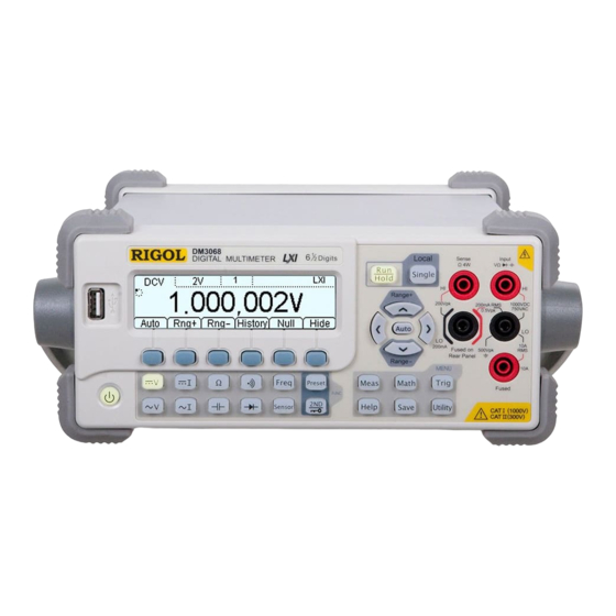
Page 11: Dm3068 Digital Multimeter Overview
RIGOL DM3068 Digital Multimeter Overview DM3068 is a 6 ½ digits, dual display digital multimeter. It was designed for users who need high precision, many functions and auto measurement, combining common measurement functions, various math operations and any sensor measurements as well as other functions. - Page 12 Configurations clone: can copy all configurations of the multimeter into other DM3068 unit using a USB flash device. English and Chinese menus, built-in help system. Powerful remote control and any sensor editing software.
-
Page 13: Document Overview
For example, the menu “REL” is expressed in this document like “REL”. Operation step: the possible procedures in this document are described using an arrow for clarity. For example, “press REL”; this sentence has a same meaning with “press and then REL”. User’s Guide of DM3068... -
Page 14: Table Of Contents
General Safety Summary................II Safety Terms and Symbols ............... VI General Care and Cleaning ..............VII Environmental Considerations ..............VIII DM3068 Digital Multimeter Overview ............ IX Document Overview ................XI Chapter 1 Quick Start ................ 1-1 General Inspection ................. 1-2 Handle Adjustment ................. - Page 15 External Storage ................2-64 To Save a File ................2-65 Utility ....................2-66 Command Set ................2-66 Interface Configurations ..............2-67 System Configuration ..............2-74 Chapter 3 Remote Control ..............3-1 Web Page Control .................. 3-2 User’s Guide of DM3068 XIII...
- Page 16 Other Measurement Characteristics ............6-17 General Specifications ................6-19 Chapter 7 Appendix ................7-1 Appendix A: DM3068 Accessories ............7-1 Appendix B: Warranty ................7-2 Appendix C: Have Comment On Our Document? ........7-3 Index ......................1 User’s Guide for DM3068...
-
Page 17: Chapter 1 Quick Start
Handle Adjustment Appearance and Dimensions The Front Panel The Rear Panel User Interface First-use of Multimeter Measurement Connections Using the Built-in Help System Using a Rackmount Kit User’s Guide for DM3068... -
Page 18: General Inspection
In case of any damage, or defect, or failure, notify your RIGOL sales representative. 3. Check the accessories Please check the accessories according to the packing lists. If the accessories are incomplete or damaged, please contact your RIGOL sales representative. User’s Guide for DM3068... -
Page 19: Handle Adjustment
To adjust the handle position of the multimeter, grip the handle in both sides and pull it outward, then rotate the handle to a desired position, see figure below. Figure 1-1 Handle Adjustment Viewing Position Carrying Position Figure 1-2 Locate the Multimeter User’s Guide of DM3068... -
Page 20: Appearance And Dimensions
Chapter 1 Quick Start RIGOL Appearance and Dimensions Figure 1-3 Front Elevation Unit: mm Figure 1-4 Side Elevation Unit: mm User’s Guide for DM3068... -
Page 21: The Front Panel
3. Auto Trigger/Reading Hold Continuously pressing this key can switch between auto trigger and reading hold functions. Auto Trigger: the backlight always on; the multimeter continuously takes readings at the fastest rate possible for the present configuration. User’s Guide of DM3068... - Page 22 FREQ, TC (thermoelectric couple), RTD (resistance temperature detectors), THERM (thermistor). Common Function Keys Quickly save or recall at least 10 groups of instrument settings. Secondary Function key Enables the dual display. Quickly saves the current instrument configuration in connection with User’s Guide for DM3068...
- Page 23 Enables auto range. Configures the measurement parameters. Selects the digit position while entering a parameter. Increases or decreases the measurement range. Enters desired numeric value while setting a parameter. Pages up or down. User’s Guide of DM3068...
- Page 24 Chapter 1 Quick Start RIGOL 10. Signal Input Terminals The measured signal (device) will be connected into the multimeter through these terminals. Different measured objects have different connection methods. for details please see “Measurement Connections”. User’s Guide for DM3068...
-
Page 25: The Rear Panel
3) Place a new specified fuse. 4) Reinstall the fuse seat into the slot. NOTE: The high current fuse stands inside the multimeter and is not allowed to be replaced by users themselves. If such work must be User’s Guide of DM3068... -
Page 26: Lan Port
VM output is enabled ( VMC ON). 6. Ext Trig Input Triggers the multimeter by connecting a trigger pulse through [Ext Trig] connector. Note the external trigger source must be selected ( Source Ext). 1-10 User’s Guide for DM3068... -
Page 27: Rs232 Port
In order to avoid electric shock or fire, please just use the specified fuse and make sure the fuse holder is in good connection and not shorted. 10. Voltage Selector Select a proper voltage scale according to the used AC supply: 115 V or 230 V. User’s Guide of DM3068 1-11... -
Page 28: Power Switch
RIGOL 11. Power Switch Connect or disconnect the AC supply. If the front power button is disabled System Cfg Switch OFF), turning on this switch will directly start up the multimeter. 1-12 User’s Guide for DM3068... -
Page 29: User Interface
LXI: LAN Control Measurement parameter Rmt: Remote Control Mode Range REL on Local: Local Control : USB Storage Main Function Run Indication Vice Reading Main Reading Vice Function Operation Menus Figure 1-10 User Interface (Dual Display) User’s Guide of DM3068 1-13... -
Page 30: First-Use Of Multimeter
2) Make sure the rear power switch is turned on. 3) Try to restart the multimeter, if it fails, check the power fuse and replace a new one when necessary. 4) If the problem still remains, contact RIGOL. 1-14 User’s Guide for DM3068... -
Page 31: Measurement Connections
Chapter 1 Quick Start RIGOL Measurement Connections DM3068 was designed with many measurement functions and different measurements have different connections. Do not discretionarily switch the measurement function when measuring as it may cause damage to the multimeter. For example, when the test leads are connected to the related current terminals, AC voltage measurement should not be taken. - Page 32 Only use 10 A and LO terminals for measurements when the measured current AC+DC RMS value goes within 200 mA and 10 A. Resistance Measurement (2-wire) Resistance Measurement (4-wire) Capacitance Measurement Capacitance Continuity Measurement Diode Measurement Open or Open or Closed Circuit Closed Circuit 1-16 User’s Guide for DM3068...
- Page 33 Frequency/Period Measurement (For DCV, 2WR, FREQ, TC, 2-wire RTD and THERM sensors) Sensor AC Signal AC Signal Any Sensor Measurement Any Sensor Measurement (For DCI sensor) (For 4WR and 4-wire RTD sensors) Sensor + Sensor - User’s Guide of DM3068 1-17...
-
Page 34: Using The Built-In Help System
Help Topics 1. The method of the test leads. 2. Common measurement. 3. Math. 4. Sensor. 5. Store and recall. 6. Utility. 7. I/O interface. 8. Online help. 9. To change the power fuse. 10. Support. 1-18 User’s Guide for DM3068... -
Page 35: Using A Rackmount Kit
Chapter 1 Quick Start RIGOL Using a Rackmount Kit DM3068 can be mounted in a standard 19-inch rack cabinet. Before any kit installations, please remove the package or cushioning material from the multimeter body. Kit Parts List Table 1-2 Kit Parts List... -
Page 36: Tool Requirements
Chapter 1 Quick Start RIGOL Tool Requirements A PH2 cross screwdriver is recommended. 1-20 User’s Guide for DM3068... -
Page 37: Space Requirements
Chapter 1 Quick Start RIGOL Space Requirements The DM3068 should be mounted under the following spaces: The machine cabinet should be a standard 19-inch one. At least a 3U space (133.5 mm) should be provided by machine cabinet. ... -
Page 38: Procedure Of Installation
Then, push the unit upward to release it from the instrument. 2. Install left and right plates: aim the detents of right and left plates at the openings on support board and insert selectively, then fix them using eight M4 screws. 1-22 User’s Guide for DM3068... - Page 39 3. Place the instrument: aim the parallels at the corresponding openings and then put the multimeter onto the support board. 4. Fix the instrument: fasten or fit the instrument tightly into the support board using two fixed fingers in connection with four M4 screws. User’s Guide of DM3068 1-23...
- Page 40 19-inch machine cabinet using four M6 screws and four M6 square nuts, respectively. 7. Note the rock holds a height of 3U, holes in compliance with the arrow direction are the mounting holes for rack. 1-24 User’s Guide for DM3068...
-
Page 41: Chapter 2 Front-Panel Operations
To Set the Range To Set the Resolution Basic Measurements To Measure Any Sensor Preset Mode Secondary Function Key Measurement Configuration Math Operations Trigger Save and Recall Utility User’s Guide for DM3068... -
Page 42: To Set The Range
In FREQ/PERIOD measurements, the multimeter uses different gate times to include all input signals within 3 Hz and 1 MHz. The ranges in CONT and DIODE measurements are fixed at 2 kΩ and 2 V, respectively. User’s Guide for DM3068... -
Page 43: To Set The Resolution
RIGOL To Set the Resolution The DM3068 holds reading resolutions of 3 ½ , 4 ½ , 5 ½ and 6 ½ digits. It automatically selects a reading resolution according to the current measurement settings. The greater the resolution is, the higher the measurement accuracy; the lower the resolution is, the faster the measurement. - Page 44 10 ms 100 ms 100 ms 4. The resolution is 3 ½ in CAP measurement. 5. The resolution is 5 ½ in SENSOR measurement. 6. The resolutions are 4 ½ in both CONT and DIODE measurements. User’s Guide for DM3068...
-
Page 45: Basic Measurements
1000 V range is selected. 4. Set the measurement parameters (Optional) The DCV measurement allows users to configure the integration time, dc impedance and auto zero. For details please see “Measurement Configuration”. 5. Read the measured value User’s Guide of DM3068... - Page 46 For more details please see “Save and Recall”. 8. Hide the menu In order to observe the measurement results clearly, users can hide the operation menu by pressing Hide. Repressing this key will redisplay the operation menu. User’s Guide for DM3068...
-
Page 47: To Measure Ac Voltage
The multimeter then measures the input signal according to the current settings and displays the value on the screen. During the ACV measurement, user can also enable the frequency measurement. Press first and then to enable the synchronous measurement, see figure below. User’s Guide of DM3068... - Page 48 For more details please see “Save and Recall”. 8. Hide the menu In order to observe the measurement results clearly, users can hide the operation menu by pressing Hide. Repressing this key will redisplay the operation menu. User’s Guide for DM3068...
-
Page 49: To Measure Dc Current
10 A. If the reading beyond 10.5 A in the range of 10 A, the screen displays “OVER LOAD”. In order to obtain more accurate measurement results, DM3068 deals with input currents having quantity of electricity separately. The multimeter will use low current scale when a current within 200 mA is input and then change to high current scale once a current that equal to or higher than 2 A is input. - Page 50 For more details please see “Save and Recall”. 8. Hide the menu In order to observe the measurement results clearly, users can hide the operation menu by pressing Hide. Repressing this key will redisplay the operation menu. 2-10 User’s Guide for DM3068...
-
Page 51: To Measure Ac Current
10 A. If the reading beyonds 10.5 A in the range of 10 A, the screen displays “OVER LOAD”. In order to obtain more accurate measurement results, DM3068 deals with input currents having quantity of electricity separately. The multimeter will use low current scale when a current within 200 mA is input and then change to high current scale once a current that equal to or higher than 2 A is input. - Page 52 Save: enables you to store the current measurement data into the internal memory or an external USB flash device. Pressing this key will light the button. For more details please see “Save and Recall”. 8. Hide the menu 2-12 User’s Guide for DM3068...
- Page 53 Chapter 2 Front-panel Operations RIGOL In order to observe the measurement results clearly, users can hide the operation menu by pressing Hide. Repressing this key will redisplay the operation menu. User’s Guide of DM3068 2-13...
-
Page 54: To Measure Resistance
Input Protection: a 1000 V protection is available in all ranges. 10% over range exists on all ranges. DM3068 provides 2-wire (2WR) and 4-wire (4WR) resistance measurements. When the measured resistance less than 100 kΩ, the 4-wire resistance measurement is suggested to be used to reduce the measurement error caused by... - Page 55 Up to 5000 latest measured data can be viewed. Press History to enter the following interface. Info: provides information about measurement. Press up or down direction key to go to the desired item. List: contains all measurement results since last update in a table. Press User’s Guide of DM3068 2-15...
- Page 56 For more details please see “Save and Recall”. 8. Hide the menu In order to observe the measurement results clearly, users can hide the operation menu by pressing Hide. Repressing this key will redisplay the operation menu. 2-16 User’s Guide for DM3068...
-
Page 57: To Measure Capacitance
5. Make math operation (advanced) Perform a math operation supported by multimeter (STA, P/F, and REL) as required. Take REL for instance, the multimeter reduces the actual User’s Guide of DM3068 2-17... - Page 58 For more details please see “Save and Recall”. 7. Hide the menu In order to observe the measurement results clearly, users can hide the operation menu by pressing Hide. Repressing this key will redisplay the operation menu. 2-18 User’s Guide for DM3068...
-
Page 59: To Measure Continuity
2.2 kΩ, the multimeter screen displays the actual resistance value but does not make a buzzer. When the measured circuit has resistance greater than 2.2 kΩ, the multimeter screen displays “OPEN” but does not make a buzzer. User’s Guide of DM3068 2-19... - Page 60 Chapter 2 Front-panel Operations RIGOL 5. Hide the menu In order to observe the measurement results clearly, users can hide the operation menu by pressing Hide. Repressing this key will redisplay the operation menu. 2-20 User’s Guide for DM3068...
-
Page 61: To Measure Diode
(beeper is on) when the diode is connected, otherwise displays “OPEN”. 4. Hide the menu In order to observe the measurement results clearly, users can hide the operation menu by pressing Hide. Repressing this key will redisplay the operation menu. User’s Guide of DM3068 2-21... -
Page 62: To Measure Frequency And Period
In FREQ/PERIOD measurement, you can set the gate time or filter as required. For details please see “Measurement Configuration”. 5. Read the measured value The multimeter then measures the input signal according to the current 2-22 User’s Guide for DM3068... - Page 63 HistoG: displays the average (AVG) and standard deviation (SDEV) of measurements in a histogram. Update: refreshes Records, Maximum, Minimum, Average and User’s Guide of DM3068 2-23...
- Page 64 For more details please see “Save and Recall”. 8. Hide the menu In order to observe the measurement results clearly, users can hide the operation menu by pressing Hide. Repressing this key will redisplay the operation menu. 2-24 User’s Guide for DM3068...
-
Page 65: To Measure Any Sensor
Users can edit and modify the display unit of the measured physical quantity at will. DM3068 supports user-defined (DCV, DCI, 2WR, 4WR, FREQ) and temperature (TC, RTD, THERM) sensor measurements. - Page 66 DCI, 2WR, 4WR or FREQ sensor is used. Since the temperature sensor (TC, RTD, THERM) presets a conversion relationship on the basis of the international temperature scale and calculates the temperature according to the electrical signal (such as voltage, resistance), you can directly choose a desired temperature sensor. 2-26 User’s Guide for DM3068...
-
Page 67: User-Defined Sensor
(a-z). 1: switches to numbers entry (0-9). Del: deletes the character where the cursor locates. Done: finishes the name entry. : returns to previous menu. User’s Guide of DM3068 2-27... - Page 68 Ω if the sensor type is 2WR. Press Corrsp and enter an appropriate value by using direction keys. Note the unit to be used is the one you have set in step 3, ℃. 2-28 User’s Guide for DM3068...
-
Page 69: Measurement Range
2 groups of reference data. Curve: the calculated curve is an approximate that has a certain curvature. It applies to the data has unfavorable linearity. This arithmetic requires at least 5 groups of reference data. User’s Guide of DM3068 2-29... - Page 70 Press Save and enter a desired file name by referring to “Name/File Name input method” such as Sens1. When finished, press Done and save the current sensor configuration into the specified path: (C:\) or USB flash device (A:\). 2-30 User’s Guide for DM3068...
- Page 71 Press Apply, the multimeter starts measuring according to the current configurations. See figure below, the shown on the screen to indicates that the result is incredible. If you suspect the stored any sensor configuration files or data, press Edit to make a modification. User’s Guide of DM3068 2-31...
-
Page 72: Temperature Sensor
K ≈ °C + 273.15 Done: saves and applies the current temperature sensor configurations. For the connection method please see “Measurement Connections”. The following parts introduce each temperature sensor supported by DM3068 in details. 2-32 User’s Guide for DM3068... - Page 73 K, N, T are cheap metal thermometers. For the reference table about each thermocouple, please see the ITS-90 standards. The DM3068 provides two cold junction compensation modes: Internal cold junction temperature & Simulated cold junction temperature. Internal cold junction temperature refers to the internal temperature of the banana jack detected by the multimeter.
- Page 74 Press RTD ALPHA and select a desired value from 385 (0.00385), 389 (0.00389), 391 (0.00391) and 392 (0.00392). 3. Set the Connection Type The RTD lead usually uses 2-wire or 4-wire connection. Press the desired option and to back to the previous menu. 2-34 User’s Guide for DM3068...
- Page 75 To use the THERM sensor, press THERM and select a desired value from 2.2K, 3K, 5K, 10K and 30K as the resistance of the sensor and then press User’s Guide of DM3068 2-35...
-
Page 76: Preset Mode
Set1 (or other sets), the multimeter stores the current measurement configuration into the selected set by using the set name such as Set1. Besides, you can recall or save preset configurations by using function. For details please see “Save and Recall”. 2-36 User’s Guide for DM3068... -
Page 77: Secondary Function Key
Set1 (or Set2, Set3….), the meter stores the current measurement configurations into the selected location in the name of “Set1” (or Set2, Set3….) in addition to use , for details please see “Save and Recall”. User’s Guide of DM3068 2-37... - Page 78 Chapter 2 Front-panel Operations RIGOL 3. Quickly Enter REL Interface In addition to button, you can press REL in common measurement interface to directly enter the REL setting interface. 2-38 User’s Guide for DM3068...
-
Page 79: Measurement Configuration
Integration time, Auto zero (AZ), Offset compensation (OC) CONT Short-circuit resistance DIODE FREQ/PREIOD Gate time, AC filter SENSOR To set the measurement parameter, select a measurement function and then press . For more details please see the following content. User’s Guide of DM3068 2-39... -
Page 80: Integration Time
The integration time applies to DCV, DCI, 2WR and 4WR measurements. DM3068 provides two types of ways to set the integration time: NPLC: expresses the integration time by the power line cycles, the unit is PLC. ... -
Page 81: Dc Impedance
10MΩ: sets the input impedances in all ranges to 10MΩ. >10GΩ: sets the input impedances in ranges of 200 mV, 2 V and 20 V to >10GΩ, while in ranges of 200V and 1000V are still 10MΩ. User’s Guide of DM3068 2-41... -
Page 82: Auto Zero
The following measurement value will reduce this reading. OFF: disable the auto zero function. Whatever, the multimeter automatically takes a zero reading once the function, or range, or integration time is changed. The following measurement value will reduce this reading. 2-42 User’s Guide for DM3068... -
Page 83: Offset Compensation
OFF: the multimeter does not execute offset compensation. NOTE The offset compensation and auto zero repel each other. The used auto zero function will be disabled automatically once you turn on the offset compensation, and vice versa. User’s Guide of DM3068 2-43... -
Page 84: Ac Filter
AC filter optimizes the low-frequency accuracy and gives stability in the shortest time. It applies to ACV, ACI and FREQ/PERIOD measurements. The DM3068 provides three types of AC filters, which are slow, middle and high. The AC filter to be used is defined by the input signal frequency. -
Page 85: Short-Circuit Resistance
When continuity test is enabled, press Set will enter the following interface, from which you can set a desired value by using direction keys. The value is allowed within 1 Ω and 2000 Ω. User’s Guide of DM3068 2-45... -
Page 86: Gate Time
The gate time can be set to1 ms, 10 ms, 100 ms or 1 s, the default is 100 ms. You can select a desired gate time by pressing the corresponding soft key. 2-46 User’s Guide for DM3068... -
Page 87: Math Operations
Chapter 2 Front-panel Operations RIGOL Math Operations DM3068 provides basic math operations (STA, P/F, dBm, dB and REL) for measurement results and displays the history data through a tendency graph and histogram. In DCV, ACV, DCI, ACI, 2WR, 4WR, CAP, FREQ/PERIOD or SENSOR (except for CONT and DIODE) measurement, press to enter the following interface. -
Page 88: Math
Take the DCV for instance, press Math to enter the following interface. Press the related menu to enter the desired measurement interface. Note you can only use one math operation at a time except REL. 2-48 User’s Guide for DM3068... - Page 89 The measurement interface displays the average value, current measurement value and number of samples. When All is selected, the measurement interface displays the maximum, minimum, average values of the measured readings, mean square deviation and number of samples. User’s Guide of DM3068 2-49...
- Page 90 The main display contains the current measurement reading. The vice display presents “PASS” if the test succeed. If the current reading beyond the high or low value, the vice display shows HI 2-50 User’s Guide for DM3068...
- Page 91 FAIL or LO FAIL and makes a sound (beeper is on: System Sound). WARNING The P/F signal from pins 1 and 9 of RS232 is not compatible with the handshake signal (Carrier Detect and Ring Indicator) from standard RS232. User’s Guide of DM3068 2-51...
- Page 92 The status bar displays “dBm”. The screen center displays the result after dBm operation. Values on the lower left and right sides of the screen represent the current measurement reading and reference resistance value, respectively. 2-52 User’s Guide for DM3068...
- Page 93 The status bar displays “dB”. The screen center displays the result after dB operation. Values on the lower left and right sides of the screen represent the current measurement reading and dB preset value, respectively. User’s Guide of DM3068 2-53...
- Page 94 The status bar displays “REL”. The screen center displays the result after REL operation. Repressing REL under the main interface will close the REL operation. The identifier REL disappears. 2-54 User’s Guide for DM3068...
-
Page 95: Tendency Graph
Start: enables the multimeter to redraw the graph according to the current measurement data. PrtScn: saves the current tendency graph into an external USB flash device in BMP. Note this function is available only when an external USB flash device is well connected. User’s Guide of DM3068 2-55... -
Page 96: Histogram
Press Stop, the multimeter stops updating histogram and enters the following interface. Start: enables the multimeter to redraw the gram according to the current measurement data. Info: provides information about the current measurement. Hide: hides the operation menu. 2-56 User’s Guide for DM3068... -
Page 97: Trigger
RIGOL Trigger The DM3068 provides four types of triggers: auto, single, external and level. It reads one or more specified number of readings (up to 50 000) on every received trigger signal and allows users to set the delay time between the start of triggering and reading. -
Page 98: To Select A Trigger Source
The multimeter will trigger on a positive or negative crossing (as selected) of a specified input level and acquire measured data. NOTE Press in remote control mode will switch the multimeter into Local mode. 2-58 User’s Guide for DM3068... -
Page 99: Reading Hold
For example, if you choose 0.1%, the input signal into the multimeter is 5 V and the new reading will be displayed if reading runs outside the range of 4.9975 V and 5.0025 V for continuous three times. User’s Guide of DM3068 2-59... -
Page 100: To Set The Trigger Parameters
Manu: the delay time in this mode can be set to any value within 0 s and 3600 s. Slope: This menu allows you to select an edge type for the pulse from [Ext Trig] connector on the rear panel when using external (or level) triggering. The default is Rise. 2-60 User’s Guide for DM3068... -
Page 101: Trigger Output
VMC to enter the following interface. From this interface, you can enable or disable the trigger output. When it is enabled, the multimeter outputs a low-true pulse from the [VM Comp] connector after each measurement. User’s Guide of DM3068 2-61... -
Page 102: Save And Recall
Save: provides an access for storing the selected file by assigning a file. This menu is available only when the current disk allows the specified type of file. Erase: clears the selected file. This menu is available only when the current disk has the specified type of file. 2-62 User’s Guide for DM3068... - Page 103 Microsoft Office Excel on your computer. Sensor: saves the current sensor configuration as an “.xsen” file. SensorData: saves the current sensor measurement result as an “.xsda” file. User’s Guide of DM3068 2-63...
-
Page 104: Internal Storage
To use the external storage, insert an USB flash device into the USB Host interface on the front panel and wait until the screen appears an icon on the status bar. USB Host MENU FUNC CAUTION Do not remove the USB flash device under “A:\” disk operations. 2-64 User’s Guide for DM3068... -
Page 105: To Save A File
(a-z) input. 1: switches to numbers (0-9) input. Del: deletes the character where the cursor locates. Done: finishes the name entry. : returns to previous menu. User’s Guide of DM3068 2-65... -
Page 106: Utility
System: involves system parameters setup such as language. T/C: executes self-test and listing error information and so on. Command Set The DM3068 supports the command sets of RIGOL (DM3068), Agilent 34401A and Fluke 45. Press Cmd to enter the following interface, from which you can choose a desired command set. -
Page 107: Interface Configurations
Chapter 2 Front-panel Operations RIGOL Interface Configurations The DM3068 provides some remote interfaces such as LAN, GPIB, USB (configure-free) and RS232 for users to execute remote control. Press I/O to enter the following interface. User’s Guide of DM3068 2-67... - Page 108 2. To Set IP Configuration Mode The IP address mode can be set to DHCP, AutoIP or ManualIP. Different modes may have differences in parameter configuration. 2-68 User’s Guide for DM3068...
- Page 109 0 to 223 (except for 127) and the others range from 0 to 255. Please ask your network administrator for an available IP address as possible as you can. Press IPAddr and enter a desired IP address by using direction keys. Mask: User’s Guide of DM3068 2-69...
- Page 110 Press Apply to enable the current network parameters. 5. To Restore Factory Defaults Press Default to restore the network parameters to defaults, in which the DHCP and AutoIP are ON and the ManualIP is disabled. 2-70 User’s Guide for DM3068...
- Page 111 AC 250V T125mA Press I/O GPIB to enter the following interface. The GPIB address can be any integer within 0 and 30. The default is 7. This setting is stored in nonvolatile storage. User’s Guide of DM3068 2-71...
- Page 112 *Remark: Pins 1 and 9 always outputs high electrical level when P/F output is disabled. WARNING The P/F signal from pins 1 and 9 of RS232 is not compatible with the handshake signal (Carrier Detect and Ring Indicator) from standard RS232. 2-72 User’s Guide for DM3068...
- Page 113 DTR/DSR pins into a logic high level. 2. Print Press Print to enter the following interface, from which you can turn on or off the measured data output from serial ports. User’s Guide of DM3068 2-73...
-
Page 114: System Configuration
Chapter 2 Front-panel Operations RIGOL System Configuration To Select a Language DM3068 supports bilingual (English-Chinese) menus, built-in helps, context helps, and messages. Press System Lang to enter the following interface and choose a desired language type. To Set the Display Parameter Press ... - Page 115 Sets the display type of the data’s decimal point on the screen to “ ” or “ ”. 2. Separte Sets the display format of data separator on the screen to “ ”, “None” or “Space”. For example: Decimal point: Separator: Decimal point: Separator: Space User’s Guide of DM3068 2-75...
- Page 116 Table 2-8 Factory defaults Parameter Factory Default Measurement Parameters *Short-circuit Resistance 10 Ω AC Filter DC Input Impedance 10 MΩ Reading Resolution 6 ½ Measurement Function Range Auto 2-76 User’s Guide for DM3068...
- Page 117 Saved Instrument Parameters and Data No change Remote Interfaces *GPIB Address *Interface *Baud Rate 9600 *Parity Check None (8 data bit) *HS (Handshake) Remark*: Parameters marked with data * in the above table are stored in nonvolatile storage. User’s Guide of DM3068 2-77...
- Page 118 To remove the cursor, press left or right direction key. To change the data, press up or down direction key. When finished, press Done to apply the setting. To Perform the Self-Test DM3068 can automatically detect the system hardware and display the results in error list. Press T/C to enter the following interface.
-
Page 119: Chapter 3 Remote Control
This chapter guides you how to control the multimeter from a distance by using either virtual panel based on web page or commands. The chapter contains the following topics: Web Page Control Command Control User’s Guide for DM3068... -
Page 120: Web Page Control
Chapter 3 Remote Control RIGOL Web Page Control DM3068 confirms to LXI-C standard and can be remotely controlled via web page. Please take the following steps: 1. Setting the LAN Connect the multimeter to LAN, set and obtain the IP address by referring to “Interface Configurations”... - Page 121 (the default user name and password are empty). 3) Web Control provides the same function operations as the front panel, from which you can configure the related parameters and obtain the measurement result. See figure below. User’s Guide of DM3068...
- Page 122 After you enter the old password once and the new password twice, click Apply and the page appears “Note: Your password setting successful”. 6) LXI provides an access for directly entering the LXI association official website http://www.lxistandard.org/. User’s Guide for DM3068...
-
Page 123: Command Control
Automation Explorer from NI (National Instruments Corporation) or Agilent IO Libraries Suite from Agilent (Agilent Technologies, Inc.) as required. The DM3068 uses USB, LAN, RS232 or GPIB interface to communicate with PC. The next part will introduce how to control the instrument by using Ultra Sigma through the interfaces mentioned above. -
Page 124: Through Usb
RIGOL Through USB 1. Connect the Instrument Connect the USB Device interface of DM3068 to the PC USB Host interface using a USB cable. 2. Install the USB Driver DM3068 digital multimeter is a USBTMC device. After the connection between the instrument and PC, turn on both devices and you will see a Hardware Update Wizard dialog box on the PC for installing “USB Test and... - Page 125 RIGOL 5. Test the Communication Right click the source name DM3068 (USB0::0x1AB1::0x0C94::DM3A020100823::INSTR) then select SCPI Panel Control to open the remote command control panel, from which you can send commands and read data. See figure below. User’s Guide of DM3068...
-
Page 126: Through Lan
Open the Ultra Sigma and click to search the instrument resource connected to LAN. The status bar becomes the following status in process of searching. 4. View LAN Device The searched instruments are shown under RIGOL Online Resource, see figure below. User’s Guide for DM3068... - Page 127 Chapter 3 Remote Control RIGOL 5. Test the Communication Right click the source name DM3068 (TCPIP::172.16.3.133::INSTR) and then select SCPI Panel Control to open the remote command control panel, from which you can send commands and read data. See figure below.
-
Page 128: Through Gpib
Click Test to verify if the GPIB communication is succeed. If failed, follow the guides. 4. View GPIB Device Click OK, the software return to its main interface. The searched instruments are shown under RIGOL Online Resource, see figure below. 3-10 User’s Guide for DM3068... - Page 129 Chapter 3 Remote Control RIGOL 5. Test the Communication Right click the source name DM3068 (GPIB0::25::INSTR) and then select SCPI Panel Control to open the remote command control panel, from which you can send commands and read data. See figure below.
-
Page 130: Through Rs232
When succeed, the searched devices are shown in the right side of the panel, otherwise, follow the guides. 4. View RS232 Device Click OK, the software returns to the main interface and searched instruments are shown under RIGOL Online Resource, see figure below. 3-12 User’s Guide for DM3068... - Page 131 Chapter 3 Remote Control RIGOL 5. Test the Communication Right click the source name DM3068 (ASRL1::INSTR) and then choose SCPI Panel Control to open the remote command control panel, from which you can send commands and read data. See figure below.
-
Page 133: Chapter 4 Troubleshooting
(3) Check the capacity of your USB device. A USB flash device with less than 4G bytes capacity is recommended. (4) Restart the multimeter and insert the USB flash device. (5) If the problem persists please contact RIGOL for service options. User’s Guide for DM3068... -
Page 135: Chapter 5 Measurement Tutorial
This chapter guides you to eliminate the potential error that appears during your measurement in order to obtain accurate measurement result. The chapter contains the following topics: Loading Errors (DCV) True-RMS AC Measurements Crest Factor Errors (non-sinusoidal inputs) Loading Errors (ACV) User’s Guide for DM3068... -
Page 136: Loading Errors (Dcv)
To reduce the effects of loading errors and minimize noise pickup, you can set the input resistance of the multimeter to “>10GΩ” in the range of 200 mV, 2 V and 20 V, and “10MΩ” for the 200 V and 1000 V ranges. User’s Guide for DM3068... -
Page 137: True-Rms Ac Measurements
RIGOL True-RMS AC Measurements The AC measurement of DM3068 has true RMS response. The power dissipated in a resistor over a period of time is proportional to the square of the measured true RMS voltage, whatever the waveform shape is. The DM3068 can accurately measure the true RMS voltage and current if the waveform shapes whose energy beyond the effective bandwidth of the multimeter can be negligible. - Page 138 AC+DC true RMS value. In order to obtain the best AC rejection, select 6.5 digits when measuring DC voltage. User’s Guide for DM3068...
-
Page 139: Crest Factor Errors (Non-Sinusoidal Inputs)
In general, the greater the crest factor, the greater the energy contained in high frequency harmonics. All multimeters have errors that are relevant to crest factor. Crest factor errors from DM3068 are listed in “AC Characteristics” section in chapter 6. -
Page 140: Loading Errors (Acv)
RIGOL Loading Errors (ACV) In the AC Voltage function, the input impedance of DM3068 appears as a 1MΩ resistance in parallel with 100 pF of capacitance. The test lead that you use to connect signals to the multimeter will also add additional capacitance and loading. -
Page 141: Chapter 6 Specifications
0.008 + 0.001 0.010 + 0.001 0.0006 + 0.0001 1.000000MΩ 0.002 + 0.001 0.010 + 0.001 0.012 + 0.001 0.0010 + 0.0002 10.00000MΩ 200nA 0.015 + 0.001 0.030 + 0.001 0.040 + 0.001 0.0030 + 0.0004 User’s Guide for DM3068... - Page 142 20kΩ (NPLC) 0.006 10000 10000 0.0006 0.0007 0.0015 0.0040 0.02 2500 3000 0.0004 0.0004 0.0008 0.0025 0.06 1000 0.0003 0.0003 0.0006 0.0025 0.0001 0.0002 0.0003 0.0015 0.22 0.0001 0.0002 0.0004 0.17 0.0001 0.0003 0.08 0.0002 0.035 User’s Guide for DM3068...
- Page 143 Typical value. -1dBFS, 1kHz single tone. 100us aperture time, zero trigger delay, auto zero off and 4096 samples. Measuring Characteristics DC Voltage Input Resistance 200mV, 2V, 20V ranges: Selectable 10MΩ or >10GΩ (For these ranges, input beyond ± 26V are clamped through 106kΩ (typical) ) User’s Guide of DM3068...
- Page 144 Externally accessible 500mA, 250V fast blow fuse at the rear panel for 200uA, 2mA, 20mA and 200mA ranges. Internal 10A, 250 V slow blow fuse for 2A and 10A ranges. Continuity/Diode Test Response Time 300 samples/sec, with audible tone Continuity Threshold Adjustable from 1 Ω to 2000 Ω Autozero OFF Operation (typical value) User’s Guide for DM3068...
- Page 145 Reading settling times are affected by source impedance, cable dielectric characteristics and input signal changes. The default measurement delay is selected to give first reading right for most measurements. Measurement Considerations Telon or other high-impedance, low-dielectric absorption wire insulation is recommended for these measurements. User’s Guide of DM3068...
-
Page 146: Ac Characteristics
1.00 + 0.02 1.00 + 0.03 1.00 + 0.03 0.100 + 0.003 5Hz-10Hz 0.35 + 0.02 0.35 + 0.03 0.35 + 0.03 0.035 + 0.003 10Hz-20kHz 0.04 + 0.02 0.07 + 0.03 0.08 + 0.03 0.008 + 0.003 User’s Guide for DM3068... - Page 147 0.35 + 0.06 0.35 + 0.06 0.35 + 0.06 0.035 + 0.006 10Hz-5kHz 0.15 + 0.06 0.15 + 0.06 0.15 + 0.06 0.015 + 0.006 5kHz-10kHz 0.35 + 0.70 0.35 + 0.70 0.35 + 0.70 0.030 + 0.006 User’s Guide of DM3068...
- Page 148 Specifications are for sinewave input >5% of range. For inputs within 1% to 5% of range, add 0.1% of range additional error. Specifications are typical values for 200uA and 2mA, 2A and 10A ranges when frequency >1kHz. Measuring Characteristics True RMS AC Voltage User’s Guide for DM3068...
- Page 149 Applying >300Vrms (or >5Arms) will cause self-heating in signal-conditioning components and these error are included in the instrument specifications. Internal temperature changes due to self-heating may cause additional error on lower ac voltage ranges. The additional error will be lower than 0.02% of User’s Guide of DM3068...
-
Page 150: Frequency And Period Characteristics
For frequency ≤300kHz, the specification is the 10% to 110% of range of the AC input voltage. For frequency >300kHz, the specification is the 20% to 110% of range of the AC input voltage. The maximum input is limited to 750V rms or 8 x 10 Volts-Hz (whichever is less). 200mV range is full range 6-10 User’s Guide for DM3068... - Page 151 Errors will occur when attempting to measure the frequency or period of an input following a dc offset voltage change. Make sure the RC circuit of input terminal has been fully settled (about 1s) before accurate measurement. User’s Guide of DM3068 6-11...
-
Page 152: Capacitance Characteristics
Apply constant current into the capacitance, and measure the voltage changing rate. Connection Type 2-wire Measurement Considerations Since small capacitance measurements are susceptible to the external noise, shielding inputs from external noise pickup is critical for minimizing measurement errors. 6-12 User’s Guide for DM3068... -
Page 153: Temperature Characteristics
Specification is for 4WR sensor measurement or 2WR measurement using REL operation. Relative to cold junction temperature, accuracy is based on ITS-90. Built-in cold junction temperature refers to the temperature inside the banana jack and its accuracy is ± 2.5 ℃. User’s Guide of DM3068 6-13... - Page 154 The built-in cold junction temperature tracks the temperature inside the banana jack. The change of the temperature in banana jack might cause additional error. When using the built-in cold junction compensation, connect the sensor terminal of the thermocouple to the banana jack and warm it up for more than 3 minutes to minimize the error. 6-14 User’s Guide for DM3068...
-
Page 155: Measurement Rate
3Hz AC Filter AC Current 20Hz 200Hz 200Hz Frequency and 1s Gate Time Period 0.1s 0.01s 0.001s Capacitance Auto trigger, zero trigger delay, auto zero off, auto range off, math function off and external interface off. User’s Guide of DM3068 6-15... - Page 156 The maximum rate available when trigger delay is set to 0. 20V range, fast filter, 1kHz input. Measure 20nF capacitance on 200nF range. The measurement period changes with the capacitance under test. The maximum measurement period on 100mF is 4s (typical value). 6-16 User’s Guide for DM3068...
-
Page 157: Other Measurement Characteristics
Jitter: < 50 μs (ACV, ACI, FREQ and PREIOD <2ms) Polarity: rising edge, falling edge available Maximum Rate: 300/s Minimum Pulse Width: 2μs VMC Output Level: 5V TTL compatible Output Impedance: 100Ω, typical Output Polarity: Falling Edge Pulse Width: about 2μs User’s Guide of DM3068 6-17... - Page 158 512k reading history data record Non-volatile Memory 10 sets history data storage (5000 readings/group) 5 sets sensor data storage (5000 readings/group) 10 sets instrument setup storage 5 sets Anysensor setup storage Support USB flash device backup data and setting. 6-18 User’s Guide for DM3068...
-
Page 159: General Specifications
(height× width× length): 107.0mm× 231.6mm× 290.5mm Remote Interface GPIB, 10/100Mbit LAN, USB 2.0 Full Speed Device & Host (support USB flash device), RS-232C Programming Language SCPI LXI Compatibility LXI Class C, Version 1.2 Warm-up Time 90 minutes User’s Guide of DM3068 6-19... -
Page 161: Chapter 7 Appendix
RIGOL Chapter 7 Appendix Appendix A: DM3068 Accessories Description Order Number Model DM3068 (6 ½ , dual-display) DM3068 Power Cord conforming to the standard of the country Two Test Leads (black and red) Two Alligator Clips (black and red) Standard... -
Page 162: Appendix B: Warranty
The warranty items include but not being subjected to the hint guarantee items related to tradable characteristic and any particular purpose. RIGOL will not take any responsibility in cases regarding to indirect, particular and ensuing damage. User’s Guide for DM3068... -
Page 163: Appendix C: Have Comment On Our Document
Chapter 7 Appendix RIGOL Appendix C: Have Comment On Our Document? If you have any question or comment on this document, please send email to: service@rigol.com User’s Guide of DM3068... -
Page 165: Index
To Measure DC Voltage ....2-5 LAN Controlling ......3-8 To Measure Resistance ....2-14 Math Operations ....... 2-47 To Trigger the Meter ....2-57 Measurement Connections ..1-15 USB Controlling ......3-6 Offset Compensation ....2-43 User Interface ......1-13 User’s Guide for DM3068...
Need help?
Do you have a question about the DM3068 and is the answer not in the manual?
Questions and answers