Table of Contents
Advertisement
Quick Links
Advertisement
Table of Contents

Related Manuals for Rigol DM3068-OB


Summary of Contents for Rigol DM3068-OB
- Page 1 RIGOL User’s Guide DM3068 Digital Multimeter Dec. 2010 RIGOL Technologies, Inc.
-
Page 3: Guaranty And Declaration
Notices RIGOL products are protected by patent law in and outside of P.R.C. RIGOL reserves the right to modify or change parts of or all the specifications and pricing policies at company’s sole decision. Information in this publication replaces all previously corresponding material. -
Page 4: Safety Requirement
RIGOL Safety Requirement General Safety Summary Please review the following safety precautions carefully before putting the instrument into operation so as to avoid any personal injuries or damages to the instrument and any product connected to it. To prevent potential hazards, please use the instrument only specified by this manual. - Page 5 Do Not Operate With Suspected Failures. If you suspect damage occurs to the instrument, have it inspected by qualified service personnel before further operations. Any maintenance, adjustment or replacement especially to circuits or accessories must be performed by RIGOL authorized personnel. Keep Well Ventilation.
- Page 6 RIGOL Input Terminal Protection Limit The protection limit applies to input terminals: 1. Main input (HI and LO) terminals HI and LO terminals are used for Voltage, Resistance, Capacitance, Continuity, Frequency and Diodes measurements and should be used under the following two conditions: 1) HI-LO protection limit: at most 1000 VDC or 750 VAC, this is also the maximum measurable voltage.
- Page 7 RIGOL 2) Only use 10 A and LO terminals for measurements when the measured current AC+DC RMS value goes within 200 mA and 10 A. 3) Select a proper current input terminal according to the estimated current magnitude before connect the multimeter to AC supplies if you want to use current measurement.
-
Page 8: Safety Terms And Symbols
RIGOL Safety Terms and Symbols Terms in this Manual. These terms may appear in this manual: WARNING Warning statements indicate the conditions or practices that could result in injury or loss of life. CAUTION Caution statements indicate the conditions or practices that could result in damage to this product or other property. -
Page 9: General Care And Cleaning
RIGOL General Care and Cleaning General Care: Do not store or leave the instrument in where the instrument will be exposed to direct sunlight for long periods of time. Cleaning: Clean the instrument regularly according to its operating conditions. To clean the exterior surface, perform the following steps: Disconnect the instrument from all power sources. -
Page 10: Environmental Considerations
RIGOL Environmental Considerations The following symbol indicates that this product complies with the applicable European Union requirements according to Directives 2002/96/EC on waste electrical and electronic equipment (WEEE) and batteries. Product End-of-Life Handling The equipment may contain substances that could be harmful to the environment or human health. -
Page 11: Dm3068 Digital Multimeter Overview
RIGOL DM3068 Digital Multimeter Overview DM3068 is a 6 ½ digits, dual display digital multimeter. It was designed for users who need high precision, many functions and auto measurement, combining common measurement functions, various math operations and any sensor measurements as well as other functions. - Page 12 RIGOL Built-in ten groups of system configurations and five groups of sensor configurations with capabilities of remote control, storage or recall. Configurations clone: can copy all configurations of the multimeter into other DM3068 unit using a USB flash device.
-
Page 13: Document Overview
RIGOL Document Overview Chapter 1 Quick Start This chapter guides you to quicky familar with the front and rear panles, user interface and measurement connections of the multimeter. Chapter 2 Front-panel Operations This chapter guides you how to use functions that the multimeter has. -
Page 14: Table Of Contents
RIGOL Contents Guaranty and Declaration ................. I Safety Requirement ................. II General Safety Summary................II Safety Terms and Symbols ............... VI General Care and Cleaning ..............VII Environmental Considerations ..............VIII DM3068 Digital Multimeter Overview ............ IX Document Overview ................XI Chapter 1 Quick Start ................ - Page 15 RIGOL To Measure Resistance ..............2-14 To Measure Capacitance ..............2-17 To Measure Continuity ..............2-19 To Measure Diode ................2-21 To Measure Frequency and Period ........... 2-22 To Measure Any Sensor ................. 2-25 User-defined Sensor ............... 2-27 Temperature sensor ............... 2-32 Preset Mode ..................
- Page 16 RIGOL Command Control .................. 3-5 Through USB................... 3-6 Through LAN ................... 3-8 Through GPIB ................3-10 Through RS232 ................3-12 Chapter 4 Troubleshooting ..............4-1 Chapter 5 Measurement Tutorial ............5-1 Loading Errors (DCV) ................5-2 True-RMS AC Measurements ..............5-3 Crest Factor Errors (non-sinusoidal inputs) ..........
-
Page 17: Chapter 1 Quick Start
Chapter 1 Quick Start RIGOL Chapter 1 Quick Start This chapter guides you to quicky familar with the front and rear panles, user interface and measurement connections of the multimeter. This chapter contains the following topics: General Inspection Handle Adjustment ... -
Page 18: General Inspection
RIGOL would not be responsible for free maintenance/rework or replacement of the unit. 2. Inspect the instrument In case of any damage, or defect, or failure, notify your RIGOL sales representative. 3. Check the accessories Please check the accessories according to the packing lists. If the accessories are incomplete or damaged, please contact your RIGOL sales representative. -
Page 19: Handle Adjustment
Chapter 1 Quick Start RIGOL Handle Adjustment To adjust the handle position of the multimeter, grip the handle in both sides and pull it outward, then rotate the handle to a desired position, see figure below. Figure 1-1 Handle Adjustment... -
Page 20: Appearance And Dimensions
Chapter 1 Quick Start RIGOL Appearance and Dimensions Figure 1-3 Front Elevation Unit: mm Figure 1-4 Side Elevation Unit: mm User’s Guide for DM3068... -
Page 21: The Front Panel
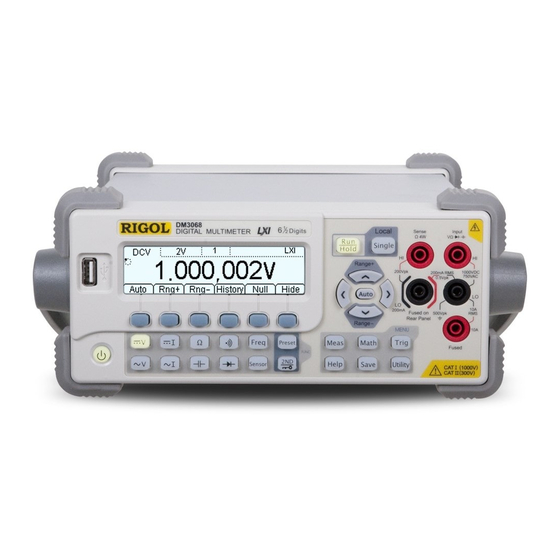
Chapter 1 Quick Start RIGOL The Front Panel 1.USB Host 2.LCD 3.Auto Trigger 4.Single Trigger /Reading Hold /Local Mode MENU FUNC 5.Power 6. Measurement 7. Menu Operation 8.Advanced 9.Range 10.Signal Input Button Function Keys Keys Menu Keys /Direction Keys Figure 1-5 Front Panel Overview 1. - Page 22 Chapter 1 Quick Start RIGOL Reading Hold: the backlight blinks; the multimeter obtains a stable reading and displays. 4. Single Trigger/Local Mode Pressing this key during the front panel operation will cause the multimeter generate one reading or specified number of readings (S No.) and then wait for the next trigger.
- Page 23 Chapter 1 Quick Start RIGOL Quickly enters the setting interface of relative measurement. 7. Operation Menu Keys Activates the corresponding menu. 8. Assistant Functions Sets all the measurement parameters. Performs math operations (statistic, P/F, dBm, dB, REL) for measured results and displays real-time measurements in trend graph and histogram.
- Page 24 Chapter 1 Quick Start RIGOL 10. Signal Input Terminals The measured signal (device) will be connected into the multimeter through these terminals. Different measured objects have different connection methods. for details please see “Measurement Connections”. User’s Guide for DM3068...
-
Page 25: The Rear Panel
Chapter 1 Quick Start RIGOL The Rear Panel 1.Curr Input Fuse 2. LAN Port 3.GPIB Port 4.Power Socket ~Line(25VA Max) Fuse AC 100-120V 45-440Hz AC 250V T250mA AC 200-240V 45-66Hz AC 250V T125mA 6.Ext Trig Input 8.RS232 Port 10.Voltage Selector 5.VMC Output... - Page 26 Chapter 1 Quick Start RIGOL done, send your multimeter back to the factory. 2. LAN Port Provides the multimeter an access to LAN for remote controlling. The multimeter conforms to LXI-C standards; it can be used in connection with other standard devices for a testing system built, easily approaching a LAN based system integration.
- Page 27 Chapter 1 Quick Start RIGOL 7. USB Device Port Communicates with a computer and controls your multimeter through PC software. It is available for USB-TMC devices. 8. RS232 Port Provides an access for multimeter controlling through PC software and outputs P/F test result.
- Page 28 Chapter 1 Quick Start RIGOL 11. Power Switch Connect or disconnect the AC supply. If the front power button is disabled System Cfg Switch OFF), turning on this switch will directly start up the multimeter. 1-12...
-
Page 29: User Interface
Chapter 1 Quick Start RIGOL User Interface Single Display Figure 1-9 User Interface (Single Display) Dual Display Math 学 LXI: LAN Control Measurement parameter Rmt: Remote Control Mode Range REL on Local: Local Control : USB Storage Main Function Run Indication... -
Page 30: First-Use Of Multimeter
2) Make sure the rear power switch is turned on. 3) Try to restart the multimeter, if it fails, check the power fuse and replace a new one when necessary. 4) If the problem still remains, contact RIGOL. 1-14 User’s Guide for DM3068... -
Page 31: Measurement Connections
Chapter 1 Quick Start RIGOL Measurement Connections DM3068 was designed with many measurement functions and different measurements have different connections. Do not discretionarily switch the measurement function when measuring as it may cause damage to the multimeter. For example, when the test leads are connected to the related current terminals, AC voltage measurement should not be taken. - Page 32 Chapter 1 Quick Start RIGOL Select a proper current input terminal according to the estimated current magnitude before connect the multimeter to AC supplies if you want to use current measurement. Only use 10 A and LO terminals for measurements when the measured current AC+DC RMS value goes within 200 mA and 10 A.
- Page 33 Chapter 1 Quick Start RIGOL Any Sensor Measurement Frequency/Period Measurement (For DCV, 2WR, FREQ, TC, 2-wire RTD and THERM sensors) Sensor AC Signal AC Signal Any Sensor Measurement Any Sensor Measurement (For DCI sensor) (For 4WR and 4-wire RTD sensors)
-
Page 34: Using The Built-In Help System
Chapter 1 Quick Start RIGOL Using the Built-in Help System The built-in help system provides information for users to quickly recall and use the basic functions of the instrument as well as how to use the built-in help system, including key (front panel) help and menu help. Press to enter the following interface. -
Page 35: Using A Rackmount Kit
Chapter 1 Quick Start RIGOL Using a Rackmount Kit DM3068 can be mounted in a standard 19-inch rack cabinet. Before any kit installations, please remove the package or cushioning material from the multimeter body. Kit Parts List Table 1-2 Kit Parts List... -
Page 36: Tool Requirements
Chapter 1 Quick Start RIGOL Tool Requirements A PH2 cross screwdriver is recommended. 1-20 User’s Guide for DM3068... -
Page 37: Space Requirements
Chapter 1 Quick Start RIGOL Space Requirements The DM3068 should be mounted under the following spaces: The machine cabinet should be a standard 19-inch one. At least a 3U space (133.5 mm) should be provided by machine cabinet. ... -
Page 38: Procedure Of Installation
Chapter 1 Quick Start RIGOL Procedure of Installation This operation should be executed only by authorized officer. Improper or incorrect operations may cause installation fails or damages to the multimeter. 1. Remove the handle from the multimeter: grip the handle in both sides and pull it outward. - Page 39 Chapter 1 Quick Start RIGOL 3. Place the instrument: aim the parallels at the corresponding openings and then put the multimeter onto the support board. 4. Fix the instrument: fasten or fit the instrument tightly into the support board using two fixed fingers in connection with four M4 screws.
- Page 40 Chapter 1 Quick Start RIGOL 5. Mount the front panel: aim the front panel opening at the front of instrument and fix them using four M4 screws. 6. Load into machine cabinet: mount the rack with instrument-fixed onto a standard 19-inch machine cabinet using four M6 screws and four M6 square nuts, respectively.
-
Page 41: Chapter 2 Front-Panel Operations
Chapter 2 Front-panel Operations RIGOL Chapter 2 Front-panel Operations This chapter guides you how to use functions that the multimeter has. The chapter contains the following topics: To Set the Range To Set the Resolution Basic Measurements ... -
Page 42: To Set The Range
Chapter 2 Front-panel Operations RIGOL To Set the Range The multimeter allows users to select a range manually and automatically. The manual mode can bring a lot of convenience for users and the others provide higher reading precision. To set a range, use function keys on the front panel or menu keys. -
Page 43: To Set The Resolution
Chapter 2 Front-panel Operations RIGOL To Set the Resolution The DM3068 holds reading resolutions of 3 ½ , 4 ½ , 5 ½ and 6 ½ digits. It automatically selects a reading resolution according to the current measurement settings. The greater the resolution is, the higher the measurement accuracy; the lower the resolution is, the faster the measurement. - Page 44 Chapter 2 Front-panel Operations RIGOL Table 2-3 Relationship between the resolution and gate time Resolution Gate Time Status bar shown 1 ms 1 ms 10 ms 10 ms 100 ms 100 ms 4. The resolution is 3 ½ in CAP measurement.
-
Page 45: Basic Measurements
Chapter 2 Front-panel Operations RIGOL Basic Measurements To Measure DC Voltage Range: 200 mV, 2 V, 20 V, 200 V, 1000 V Max Resolution: 100 nV (in the range of 200 mV) Input Protection: a 1000 V protection is available in all ranges and a 10% over range exists on all ranges except for 1000 V. - Page 46 Chapter 2 Front-panel Operations RIGOL The multimeter then measures the input signal according to the current settings and displays the value on the screen. 6. Make math operation (advanced) Perform a math operation supported by multimeter (STA, P/F, dBm, dB, REL) as required.
-
Page 47: To Measure Ac Voltage
Chapter 2 Front-panel Operations RIGOL To Measure AC Voltage Range: 200 mV, 2 V, 20 V, 200 V, 750 V Max Resolution: 100 nV (in the range of 200 mV) Input Protection: a 750 V protection is available in all ranges and a 10% over range exists on all ranges except for 750 V. - Page 48 Chapter 2 Front-panel Operations RIGOL 6. Make math operation (advanced) Perform a math operation supported by multimeter (STA, P/F, dBm, dB, REL) as required. Take REL for instance, the multimeter reduces the actual measurement result from the pre-specified value of REL and displays the result.
-
Page 49: To Measure Dc Current
Chapter 2 Front-panel Operations RIGOL To Measure DC Current Range: 200 μA, 2 mA, 20 mA, 200 mA, 2 A, 10 A Max Resolution: 0.1 nA (in the range of 200 μA) Input Protection: the multimeter uses two kinds of fuses for current protection, one is on the rear panel for low current protection (500 mA quick-acting fuse) and the other is inside the multimeter for high current protection (10 A). - Page 50 Chapter 2 Front-panel Operations RIGOL 5. Read the measured value The multimeter then measures the input signal according to the current settings and displays the value on the screen. 6. Make math operation (advanced) Perform a math operation supported by multimeter (STA, P/F, and REL) as required.
-
Page 51: To Measure Ac Current
Chapter 2 Front-panel Operations RIGOL To Measure AC Current Range: 200 μA, 2 mA, 20 mA, 200 mA, 2 A, 10 A Max Resolution: 0.1 nA (in the range of 200 μA) Input Protection: the multimeter uses two kinds of fuses for current protection, one is on the rear panel for low current protection (500 mA quick-acting fuse) and the other is inside the multimeter for high current protection (10 A). - Page 52 Chapter 2 Front-panel Operations RIGOL 5. Read the measured value The multimeter then measures the input signal according to the current settings and displays the value on the screen. During the ACV measurement, user can also enable the frequency/period measurement. Press...
- Page 53 Chapter 2 Front-panel Operations RIGOL In order to observe the measurement results clearly, users can hide the operation menu by pressing Hide. Repressing this key will redisplay the operation menu. User’s Guide of DM3068 2-13...
-
Page 54: To Measure Resistance
Chapter 2 Front-panel Operations RIGOL To Measure Resistance Range: 200 Ω, 2 kΩ, 20 kΩ, 200 kΩ, 1 MΩ, 10 MΩ, 100 MΩ Max Resolution: 100 μΩ (in the range of 200 Ω) Input Protection: a 1000 V protection is available in all ranges. 10% over range exists on all ranges. - Page 55 Chapter 2 Front-panel Operations RIGOL The 2WR/4WR measurement allows users to configure the integration time, auto zero and offset compensation. For details please see “Measurement Configuration”. 5. Read the measured value The multimeter then measures the measured resistance according to the current settings and displays the value on the screen.
- Page 56 Chapter 2 Front-panel Operations RIGOL up or down direction key or menu softkey to go to the desired item. HistoG: displays the average (AVG) and standard deviation (SDEV) of measurements in a histogram. Update: refreshes Records, Maximum, Minimum, Average and ...
-
Page 57: To Measure Capacitance
Chapter 2 Front-panel Operations RIGOL To Measure Capacitance Range: 2 nF, 20 nF, 200 nF, 2 μF, 20 μF , 200 μF, 2 mF, 20 mF, 100 mF Max Resolution: 1 pF (in the range of 2 nF) Input Protection: a 1000 V protection is available in all ranges. 10% over range exists on all ranges. - Page 58 Chapter 2 Front-panel Operations RIGOL measurement result from the pre-specified value of REL and displays the result. For details please see “Math Operations”. 6. View history data Up to 5000 latest measured data can be viewed. Press History to enter the following interface.
-
Page 59: To Measure Continuity
Chapter 2 Front-panel Operations RIGOL To Measure Continuity Test Current Source: 1 mA Max Resolution: 0.1 Ω (the range is fixed at 2 kΩ) Input Protection: 1000 V Input Protection. Open-circuit Voltage: < 8 V Beep Threshold (short-circuit resistance): from 1 Ω to 2000 Ω... - Page 60 Chapter 2 Front-panel Operations RIGOL 5. Hide the menu In order to observe the measurement results clearly, users can hide the operation menu by pressing Hide. Repressing this key will redisplay the operation menu. 2-20 User’s Guide for DM3068...
-
Page 61: To Measure Diode
Chapter 2 Front-panel Operations RIGOL To Measure Diode Test Current Source: 1 mA Max Resolution: 100 μV (the range is fixed at 2 V) Input Protection: 1000 V Input Protection. Open-circuit Voltage: < 8 V The diode measurement is for measuring the forward voltage drop on the diode. -
Page 62: To Measure Frequency And Period
Chapter 2 Front-panel Operations RIGOL To Measure Frequency and Period Frequency (Period) Range: from 3 Hz to 1 MHz (from 0.33 s to 1 μs) Input Signal Range: 200 mV, 2 V, 20 V, 200 V, 750 V Input Protection: a 750 V protection is available in all ranges. - Page 63 Chapter 2 Front-panel Operations RIGOL settings and displays the value on the screen. Besides, the multimeter can measure voltage and current of the signal during the frequency/period measurement. Pressing and then one by one will obtain the results shown in figures below.
- Page 64 Chapter 2 Front-panel Operations RIGOL SDEV values under Info menu. This operation synchronizes with the information in List and HistoG. Save: enables you to store the current measurement data into the internal memory or an external USB flash device. Pressing this key will light the button.
-
Page 65: To Measure Any Sensor
Chapter 2 Front-panel Operations RIGOL To Measure Any Sensor This function enables you to easily convert a measured physical quantity (such as pressure, flow rate, temperature, etc.) into an easy-measured quantity such as voltage, resistance. By pre-inputting a response curve, the multimeter converts and amends the data according to the internal arithmetic for displaying. - Page 66 Chapter 2 Front-panel Operations RIGOL To create a new sensor configuration file, you can define a fitting curve when DCV, DCI, 2WR, 4WR or FREQ sensor is used. Since the temperature sensor (TC, RTD, THERM) presets a conversion relationship on the basis of the international...
-
Page 67: User-Defined Sensor
Chapter 2 Front-panel Operations RIGOL User-defined Sensor Press New User to enter the following interface. Prpty: sets the sensor name, type and unit. Define: defines the response curve of the sensor. 1. Defining the Sensor Name Press Prpty ... - Page 68 Chapter 2 Front-panel Operations RIGOL 2. Specifying the Sensor Type Press Prpty Type to enter the following interface and select a type to be converted. Press to return to previous menu. 3. Selecting the Sensor Unit Press Prpty Unit and select a desired unit for displaying. When USER is selected, you can define a unit up to 2 digits by using direction keys.
- Page 69 Chapter 2 Front-panel Operations RIGOL Table 2-4 User-defined sensor measurement range Measurement Range -1100 V to 1100 V -220 mA to 220 mA 0 Ω to 110 MΩ 0 Ω to 110 MΩ FREQ 0 Hz to 1100 kHz When you finish a pair of data entry, press Done, the multimeter goes to the following interface.
- Page 70 Chapter 2 Front-panel Operations RIGOL NOTE If the linearity of a certain data segment from the sensor relation curve is good, Line arithmetic is recommended, otherwise use Curve arithmetic. But for those curves have good and poor linearity, Segment function namely using different arithmetic for different measurement section, should be used.
- Page 71 Chapter 2 Front-panel Operations RIGOL Press and returns to User interface. Press Apply, the multimeter starts measuring according to the current configurations. See figure below, the shown on the screen to indicates that the result is incredible. If you suspect the stored any sensor configuration files or data, press Edit to make a modification.
-
Page 72: Temperature Sensor
Chapter 2 Front-panel Operations RIGOL Temperature sensor DM3068 can directly measure the temperature detected by TC (Thermocouple), RTD (Resistance Temperature Detector) and THERM (Thermistor) sensors. Different temperature sensor uses different form to convert temperature into electrical signal as its special characteristics. A temperature sensor that conforms to ITS-90 standards should be used for measurement. - Page 73 Chapter 2 Front-panel Operations RIGOL The TC (thermocouple) is one of the most common industrial thermometers. It converts the temperature value into voltage reading, and can measure temperatures in a wide range. The common thermometers are B (Pt Rh 30- Pt Rh6), E (NI CR-WRCK), J (Fe-WRCK), K (NI CR-NiSi), N (NiCrNi-NiSi), R (Pt Rh13 -Pt), S (Pt Rh10-Pt), T (Cu-WRCK).
- Page 74 Chapter 2 Front-panel Operations RIGOL RTD is a resistance temperature detector commonly used in low temperature, having high measurement accuracy, stable performance and better linearity. It measures the temperature depending on the changing resistance of the measured substance with the temperature. The multimeter will display the temperature, corresponds to changing resistance.
- Page 75 Chapter 2 Front-panel Operations RIGOL THERM The THERM (thermistor) converts the temperature reading into resistance value. It is typically sensitive to temperature, but the measurement range is limited. In this measurement, the multimeter adopts Steinhart-Hart approximate algorithm and converts the resistance from temperature sensor into the related temperature for displaying.
-
Page 76: Preset Mode
Chapter 2 Front-panel Operations RIGOL Preset Mode Preset mode applies to production lines for avoiding misoperations. Press in any mode to enter the setting interface, from which you can choose a preset configuration from up to 10 groups. Note the configurations in this interface correspond to the 10 groups of system configurations ( ... -
Page 77: Secondary Function Key
Chapter 2 Front-panel Operations RIGOL Secondary Function Key The Secondary function key is used to enable the dual display mode and quickly store the current settings in co-ordination with and enter the REL setting interface. 1. Turn On The Dual Display This mode enables you to simultaneously measure both voltage or current and frequency of an ac signal. - Page 78 Chapter 2 Front-panel Operations RIGOL 3. Quickly Enter REL Interface In addition to button, you can press REL in common measurement interface to directly enter the REL setting interface. 2-38 User’s Guide for DM3068...
-
Page 79: Measurement Configuration
Chapter 2 Front-panel Operations RIGOL Measurement Configuration Most measurement parameters are user-defined. Changing a measurement parameter will change the measurement precision and speed as well as the input impedance. An appropriate measurement parameter based on the practical application will enable the fastest measurement or highest measurement precision. -
Page 80: Integration Time
Chapter 2 Front-panel Operations RIGOL Integration Time Integration time is the period during which the multimeter’s analog-to-digital (A/D) converter samples the input signal for a measurement. The longer the integration time is, the slower the measurement speed and the higher the resolution; the shorter the integration time is, the faster the measurement and the lower the resolution. -
Page 81: Dc Impedance
Chapter 2 Front-panel Operations RIGOL DC Impedance DC impedance applies to DCV measurement. The default is 10 MΩ. In the range of 200 mV, 2 V or 20 V, you can choose “>10GΩ” to reduce the loading error to the measured object caused by multimeter (refer to “Loading Errors (DCV)”). -
Page 82: Auto Zero
Chapter 2 Front-panel Operations RIGOL Auto Zero Auto zero (Auto Zero) applies to DCV, DCI, 2WR and 4WR measurements. Press AZ to enter the following interface. ON: the multimeter internally disconnects the input signal and measured circuit after each measurement, and takes a zero reading. It then subtracts... -
Page 83: Offset Compensation
Chapter 2 Front-panel Operations RIGOL Offset Compensation OC (Offset Comp) applies to resistance measurements in the range of 200 Ω, 2 kΩ and 20 kΩ. It eliminates the impact of small dc offset from test lead to measurement result. In 2WR or 4WR measurement, when the range is set to 200 Ω, 2 kΩ or 20 kΩ, press ... -
Page 84: Ac Filter
Chapter 2 Front-panel Operations RIGOL AC Filter AC filter optimizes the low-frequency accuracy and gives stability in the shortest time. It applies to ACV, ACI and FREQ/PERIOD measurements. The DM3068 provides three types of AC filters, which are slow, middle and high. The AC filter to be used is defined by the input signal frequency. -
Page 85: Short-Circuit Resistance
Chapter 2 Front-panel Operations RIGOL Short-Circuit Resistance This function only applies to continuity test. When the measured circuit has a resistance smaller than the short-circuit resistance, the circuit is considered to connected, and the multimeter makes a buzzer (beeper is on). The default short-circuit resistance is 10 Ω... -
Page 86: Gate Time
Chapter 2 Front-panel Operations RIGOL Gate Time Gate time (also called Aperture Time) applies to FREQ/PERIOD function. It decides the resolution of low-frequency measurement. The longer the gate time, the higher the resolution of the low-frequency measurement is and the slower the measurement is, and vice versa. -
Page 87: Math Operations
Chapter 2 Front-panel Operations RIGOL Math Operations DM3068 provides basic math operations (STA, P/F, dBm, dB and REL) for measurement results and displays the history data through a tendency graph and histogram. In DCV, ACV, DCI, ACI, 2WR, 4WR, CAP, FREQ/PERIOD or SENSOR (except for CONT and DIODE) measurement, press to enter the following interface. -
Page 88: Math
Chapter 2 Front-panel Operations RIGOL Math The multimeter provides 5 math functions: STA (MAX, MIN, and AVG, ALL), P/F, dBm, dB and REL. Different measurement function allows different math functions. See table below. Table 2-6 Math Operation Measurement Function Available Math Functions... - Page 89 Chapter 2 Front-panel Operations RIGOL STA calculates the min, max, average and mean square deviation of readings during the measurement. Press STA to enter the following interface. After you choose a desired STA function, press ON to enable it and the multimeter enters the reading interface.
- Page 90 Chapter 2 Front-panel Operations RIGOL P/F operation prompts the signal testing result (message display and beep) according to the specified high and low parameters and outputs low-true pulse through the RS232 serial port on the rear panel. See figures below, the multimeter outputs a negative pulse from the Pin 1 (Pin 9) if the test succeed (or failed).
- Page 91 Chapter 2 Front-panel Operations RIGOL FAIL or LO FAIL and makes a sound (beeper is on: System Sound). WARNING The P/F signal from pins 1 and 9 of RS232 is not compatible with the handshake signal (Carrier Detect and Ring Indicator) from standard RS232.
- Page 92 Chapter 2 Front-panel Operations RIGOL dBm represents the absolute value of the power. The dBm operation calculates the power value of the reference resistance according to the measured voltage. dBm = 10 x Log [ (Reading ) / 1 mW ]...
- Page 93 Chapter 2 Front-panel Operations RIGOL dB represents the relative value. When enabled, the multimeter calculates the dBm value of the next reading and reduces the preset dB from this value and then displays the result. dB = 10 x Log...
- Page 94 Chapter 2 Front-panel Operations RIGOL The reading displayed on the screen in REL operation is the difference between measured and preset values. Reading = measured value – preset value Users can pre-specify a REL value by each of the following way: 1) In basic measurement interface, press REL, the multimeter automatically uses the current measurement result as the preset value.
-
Page 95: Tendency Graph
Chapter 2 Front-panel Operations RIGOL Tendency Graph The multimeter puts the real-time measured data into a tendency graph that users can directly observe the variation of the measured data without other supplementary means. This function is available for DCV, DCI, ACV, ACI, 2WR, 4WR, CAP, FREQ/PERIOD and SENSOR measurements. -
Page 96: Histogram
Chapter 2 Front-panel Operations RIGOL Histogram The real-time histogram displays the distribution situation of the measurement data from DCV, DCI, ACV, ACI, 2WR, and 4WR, CAP, FREQ/PERIOD and SENSOR. Note the histogram changes in real time differing from the histogram in basic measurements ( ... -
Page 97: Trigger
Chapter 2 Front-panel Operations RIGOL Trigger The DM3068 provides four types of triggers: auto, single, external and level. It reads one or more specified number of readings (up to 50 000) on every received trigger signal and allows users to set the delay time between the start of triggering and reading. -
Page 98: To Select A Trigger Source
Chapter 2 Front-panel Operations RIGOL To Select a Trigger Source Press Source to enter the following interface. The default is Auto. Auto Triggering: Press Auto and Done to enable the auto triggering. The backlight of on the front panel then turns on, and the multimeter continuously takes readings as fast it can according to the current configuration. -
Page 99: Reading Hold
Chapter 2 Front-panel Operations RIGOL Reading Hold The multimeter captures stable reading and holds it on the screen when the reading hold function is enabled. The sensitive determines whether the reading is enough stable and can be displayed on the screen. This parameter is expressed in the form of reading percentage based on the current range. -
Page 100: To Set The Trigger Parameters
Chapter 2 Front-panel Operations RIGOL To Set the Trigger Parameters Press Set to enter the following interface. S No. S No. presents the number of readings to be taken when a trigger signal is received. Press S No. and enter a desired number within 1 and 50 000 by using direction keys. -
Page 101: Trigger Output
Chapter 2 Front-panel Operations RIGOL Trigger Output Press VMC to enter the following interface. From this interface, you can enable or disable the trigger output. When it is enabled, the multimeter outputs a low-true pulse from the [VM Comp] connector after each measurement. -
Page 102: Save And Recall
Chapter 2 Front-panel Operations RIGOL Save and Recall The multimeter allows you to save the status configuration and measurement data into the internal memory or an external USB flash device for future use. Press to enter the following interface. Disk: chooses a desired storage location. “C:\” indicates an internal storage, while “A:\”... - Page 103 Chapter 2 Front-panel Operations RIGOL Storage Type The multimeter can save and recall files in types, which are: MIRR_CFG: saves all system and sensor configurations files from the internal storage into an external USB flash device in a same file. The file suffix is “.xmir”.
-
Page 104: Internal Storage
Chapter 2 Front-panel Operations RIGOL Internal Storage The internal storage (C:\) of the multimeter holds up to 10 groups of system configurations, 10 groups of measurement data, 5 groups of sensor configurations and 5 groups of sensor measurement results. External Storage The external storage (A:\) can save 6 types of files according to the used device’s... -
Page 105: To Save A File
Chapter 2 Front-panel Operations RIGOL To Save a File When the current storage disk allows specified file type, press Save to enter the following interface. From where, you can assign a name for the file to be saved. The file name should be within 9 characters. -
Page 106: Utility
System: involves system parameters setup such as language. T/C: executes self-test and listing error information and so on. Command Set The DM3068 supports the command sets of RIGOL (DM3068), Agilent 34401A and Fluke 45. Press Cmd to enter the following interface, from which you can choose a desired command set. -
Page 107: Interface Configurations
Chapter 2 Front-panel Operations RIGOL Interface Configurations The DM3068 provides some remote interfaces such as LAN, GPIB, USB (configure-free) and RS232 for users to execute remote control. Press I/O to enter the following interface. User’s Guide of DM3068 2-67... - Page 108 Chapter 2 Front-panel Operations RIGOL Set the LAN The LAN configuration parameters conform to LXI-C standards. Before using this interface, connect the multimeter into your local LAN. ~Line(25VA Max) Fuse AC 100-120V 45-440Hz AC 250V T250mA AC 200-240V 45-66Hz AC 250V T125mA Press ...
- Page 109 Chapter 2 Front-panel Operations RIGOL NOTE When all three IP configuration modes are ON, the multimeter configures in the order of DHCP, AutoIP and ManualIP. At least one IP configuration mode should be ON. 1) DHCP The DHCP server from the current network in this mode assigns network parameters to the multimeter such as IP address.
- Page 110 Chapter 2 Front-panel Operations RIGOL The format of subnet mask is nnn.nnn.nnn.nnn. All nnn ranges from 0 to 255. Please ask your network administrator for an available subnet mask as possible as you can. Press Mask and enter a desired subnet mask by using direction keys.
- Page 111 Chapter 2 Front-panel Operations RIGOL To Set the GPIB The GPIB (IEEE-488.2) interface must assign a unique address for each device connected to it. Before using this interface, have a GPIB cable to connect your multimeter with the PC. GPIB ~Line(25VA Max)...
- Page 112 Chapter 2 Front-panel Operations RIGOL To Set the RS232 Before any related operations, have a RS232 cable to connect the multimeter to a PC or data terminal equipment (DTE). Then, set the interface parameters such as baud rate, parity and handshake and match them with the PC or data terminal equipment, in order to control the meter.
- Page 113 Chapter 2 Front-panel Operations RIGOL Press I/O RS232 to enter the following interface. Set: sets RS232 interface parameters. Print: enables you to turn on or off the data output from the RS232. 1. To Set RS232 Parameters Press Set to enter the following interface, from which you can set the baud rate, parity and handshake status.
-
Page 114: System Configuration
Chapter 2 Front-panel Operations RIGOL System Configuration To Select a Language DM3068 supports bilingual (English-Chinese) menus, built-in helps, context helps, and messages. Press System Lang to enter the following interface and choose a desired language type. To Set the Display Parameter Press ... - Page 115 Chapter 2 Front-panel Operations RIGOL To Set the Beeper Press System Sound to enter the following interface. This menu determines if the multimeter makes a sound when any front-panel key is pressed and when the continuity test result is considered connected. The setting is stored in nonvolatile storage.
- Page 116 Chapter 2 Front-panel Operations RIGOL To Set the Configuration Press System Cfg to enter the following interface. 1. PwrOn Selects a system configuration to be used at power-on from “Default” and “Last” (configuration at last power-off). This setting will be available for every power-on unless you change it.
- Page 117 Chapter 2 Front-panel Operations RIGOL Math Operations Math Status Math Item Math Register All registers cleared dBm Reference Resistance 600 Ω Trigger Parameters *Delay Auto *Number of Samples 0.1% *Holding Range *Trigger Source Auto System *Beeper *Separator *Language English Normal (black text on white...
- Page 118 Chapter 2 Front-panel Operations RIGOL To Set the System Clock Press System Clock to enter the following interface. To remove the cursor, press left or right direction key. To change the data, press up or down direction key. When finished, press Done to apply the setting.
-
Page 119: Chapter 3 Remote Control
Chapter 3 Remote Control RIGOL Chapter 3 Remote Control This chapter guides you how to control the multimeter from a distance by using either virtual panel based on web page or commands. The chapter contains the following topics: Web Page Control ... -
Page 120: Web Page Control
Chapter 3 Remote Control RIGOL Web Page Control DM3068 confirms to LXI-C standard and can be remotely controlled via web page. Please take the following steps: 1. Setting the LAN Connect the multimeter to LAN, set and obtain the IP address by referring to “Interface Configurations”... - Page 121 Chapter 3 Remote Control RIGOL 2) Network Settings allows you to set the network parameters, such as IP address. To restore the factory defaults, click LAN Configuration Initialize. NOTE: A correct user name and password is required to enter the setting interface of network if the multimeter has had a password set on it (the default user name and password are empty).
- Page 122 Chapter 3 Remote Control RIGOL 4) Help contains both instrument and network information. 5) Security is for modifying the password of network setting and controlling. After you enter the old password once and the new password twice, click Apply and the page appears “Note: Your password setting successful”.
-
Page 123: Command Control
“Programming Guide” of DM3068. Use Software Offered by RIGOL or Others RIGOL specifically designed Ultra Sigma for instrument remote controlling through commands. Users can use this software or Measurement & Automation Explorer from NI (National Instruments Corporation) or Agilent IO Libraries Suite from Agilent (Agilent Technologies, Inc.) as required. -
Page 124: Through Usb
The status bar becomes the following status in process of searching. 4. View USB Device The searched instruments are shown under RIGOL Online Resource with the model and USB interface information, see figure below. User’s Guide for DM3068... - Page 125 Chapter 3 Remote Control RIGOL 5. Test the Communication Right click the source name DM3068 (USB0::0x1AB1::0x0C94::DM3A020100823::INSTR) then select SCPI Panel Control to open the remote command control panel, from which you can send commands and read data. See figure below.
-
Page 126: Through Lan
Open the Ultra Sigma and click to search the instrument resource connected to LAN. The status bar becomes the following status in process of searching. 4. View LAN Device The searched instruments are shown under RIGOL Online Resource, see figure below. User’s Guide for DM3068... - Page 127 Chapter 3 Remote Control RIGOL 5. Test the Communication Right click the source name DM3068 (TCPIP::172.16.3.133::INSTR) and then select SCPI Panel Control to open the remote command control panel, from which you can send commands and read data. See figure below.
-
Page 128: Through Gpib
Click Test to verify if the GPIB communication is succeed. If failed, follow the guides. 4. View GPIB Device Click OK, the software return to its main interface. The searched instruments are shown under RIGOL Online Resource, see figure below. 3-10 User’s Guide for DM3068... - Page 129 Chapter 3 Remote Control RIGOL 5. Test the Communication Right click the source name DM3068 (GPIB0::25::INSTR) and then select SCPI Panel Control to open the remote command control panel, from which you can send commands and read data. See figure below.
-
Page 130: Through Rs232
When succeed, the searched devices are shown in the right side of the panel, otherwise, follow the guides. 4. View RS232 Device Click OK, the software returns to the main interface and searched instruments are shown under RIGOL Online Resource, see figure below. 3-12 User’s Guide for DM3068... - Page 131 Chapter 3 Remote Control RIGOL 5. Test the Communication Right click the source name DM3068 (ASRL1::INSTR) and then choose SCPI Panel Control to open the remote command control panel, from which you can send commands and read data. See figure below.
-
Page 133: Chapter 4 Troubleshooting
Chapter 4 Troubleshooting To help you solve commonly encountered problems, we have listed some typical issues with their respective solutions. If the problems persist, contact RIGOL and prepare your device information (Utility T/C Info). 1. The screen still dark (no display) after power on: (1) Check if the power cord is well connected. -
Page 135: Chapter 5 Measurement Tutorial
Chapter 5 Measurement Tutorial RIGOL Chapter 5 Measurement Tutorial This chapter guides you to eliminate the potential error that appears during your measurement in order to obtain accurate measurement result. The chapter contains the following topics: Loading Errors (DCV) ... -
Page 136: Loading Errors (Dcv)
Chapter 5 Measurement Tutorial RIGOL Loading Errors (DCV) Measurement loading errors occur when the resistance of the device-under-test (DUT) is an appreciable percentage of the multimeter’s own input resistance. The diagram below shows this error source. Ideal Meter Vs = ideal DUT voltage Rs = DUT source resistance Ri = input resistance of the multimeter (10MΩ... -
Page 137: True-Rms Ac Measurements
Chapter 5 Measurement Tutorial RIGOL True-RMS AC Measurements The AC measurement of DM3068 has true RMS response. The power dissipated in a resistor over a period of time is proportional to the square of the measured true RMS voltage, whatever the waveform shape is. The DM3068 can accurately measure the true RMS voltage and current if the waveform shapes whose energy beyond the effective bandwidth of the multimeter can be negligible. - Page 138 Chapter 5 Measurement Tutorial RIGOL determine the DC and AC components of the signal by using DCV and ACV measurements, and then substitute the results in the formula given below and work out the AC+DC true RMS value. In order to obtain the best AC rejection, select 6.5 digits when measuring DC voltage.
-
Page 139: Crest Factor Errors (Non-Sinusoidal Inputs)
Chapter 5 Measurement Tutorial RIGOL Crest Factor Errors (non-sinusoidal inputs) A common misconception is that "since an ac multimeter is true RMS, its sine wave accuracy specifications apply to all waveforms." Actually, the shape of the input signal can dramatically affect measurement accuracy. A common way to describe signal wave shapes is “crest factor”. -
Page 140: Loading Errors (Acv)
Chapter 5 Measurement Tutorial RIGOL Loading Errors (ACV) In the AC Voltage function, the input impedance of DM3068 appears as a 1MΩ resistance in parallel with 100 pF of capacitance. The test lead that you use to connect signals to the multimeter will also add additional capacitance and loading. -
Page 141: Chapter 6 Specifications
Chapter 6 Specifications RIGOL Chapter 6 Specifications DC Characteristics Accuracy Specifications: ± (% of reading + % of range) Temperature Test Current or 24 Hour 90 Day 1 Year Coefficient Function Range Burden Voltage ℃± 1℃ ℃± 5℃ ℃± 5℃... - Page 142 RIGOL Chapter 6 Specifications 100.0000MΩ 200nA || 10MΩ 0.300 + 0.010 0.800 + 0.010 0.800 + 0.010 0.1500 + 0.0002 Diode Test 2.0000V 0.002 + 0.010 0.008 + 0.020 0.010 + 0.020 0.0010 + 0.0020 Continuity Test 2000.0Ω 0.002 + 0.010 0.008 + 0.020...
- Page 143 Chapter 6 Specifications RIGOL Typical value. Resolution is defined as the typical 20V range RMS noise (using auto zero “Once”). Normal mode rejection ratio for power-line frequency ± 0.1%. For power-line frequency ± 1%, subtract 20dB. For ± 3%, subtract 30dB.
- Page 144 RIGOL Chapter 6 Specifications 200V and 1000V ranges: 10MΩ±1% Input Protection 1000V 50pA, at 25℃, typical Input Offset Current CMRR (common mode 140dB for 1 kΩ unbalance in LO lead, ± 500VDC peak maximum. rejection ratio) Resistance Measurement Method Selectable 4-wire or 2-wire resistance...
- Page 145 Chapter 6 Specifications RIGOL Following instrument warm-up at the environment temperature ± 1℃ and <5 minutes, add 0.0001 % range + 2 uV for DCV and 2 mΩ for resistance. Settling Time Considerations Reading settling times are affected by source impedance, cable dielectric characteristics and input signal changes. The default measurement delay is selected to give first reading right for most measurements.
-
Page 146: Ac Characteristics
RIGOL Chapter 6 Specifications AC Characteristics Accuracy Specifications: ± (% of reading + % of range) Function Range Frequency Range 24 Hour 90 Day 1 Year Temperature ℃± 1℃ ℃± 5℃ ℃± 5℃ Coefficient 0℃ to (T ℃-5℃) ℃+5℃) to 50℃... - Page 147 Chapter 6 Specifications RIGOL 20kHz-50kHz 0.10 + 0.04 0.12 + 0.05 0.15 + 0.05 0.012 + 0.005 50kHz-100kHz 0.55 + 0.08 0.60 + 0.08 0.60 + 0.08 0.060 + 0.008 100kHz-300kHz 4.0 + 0.50 4.0 + 0.50 4.0 + 0.50 0.20 + 0.02...
- Page 148 RIGOL Chapter 6 Specifications 10.00000A 3Hz-5Hz 1.10 + 0.08 1.10 + 0.10 1.10 + 0.10 0.100 + 0.008 5Hz-10Hz 0.35 + 0.08 0.35 + 0.10 0.35 + 0.10 0.035 + 0.008 10Hz-5kHz 0.15 + 0.08 0.15 + 0.10 0.15 + 0.10 0.015 + 0.008...
- Page 149 Chapter 6 Specifications RIGOL Measurement Method AC-coupled True-RMS measurement with up to 400V DC of bias at on any range. Crest Factor ≤ 5 at full range Input Impedance 1MΩ ± 2% in parallel with <150pF capacitance on any range...
-
Page 150: Frequency And Period Characteristics
RIGOL Chapter 6 Specifications reading and will generally dissipate within a few minutes. Frequency and Period Characteristics [1][2] Accuracy Specifications: ± (% of reading) Function Range Frequency Range 24 Hour 90 Day 1 Year Temperature ℃± 1℃ ℃± 5℃ ℃± 5℃... - Page 151 Chapter 6 Specifications RIGOL input or input that is larger than the full range. For 20mV to 200mV, multiply % of reading error × 10. Relative to calibration standards. Measuring Characteristics Frequency and Period Measurement Method Reciprocal-counting technique, AC-coupled input using the AC voltage function.
-
Page 152: Capacitance Characteristics
RIGOL Chapter 6 Specifications Capacitance Characteristics [1][2] Accuracy Specifications: ± (% of reading + % of range) Function Range Test Current 1Year Temperature Coefficient ℃± 5℃ 0℃ to (T ℃-5℃) ℃+5℃) to 50℃ Capacitance 2.000nF 200nA 2 + 2.5 0.05+0.05 20.00nF... -
Page 153: Temperature Characteristics
Chapter 6 Specifications RIGOL Temperature Characteristics Accuracy Specifications Function Probe Type Type Optimum Range 1 Year Temperature Coefficient ℃± 5℃ 0℃ to (T ℃-5℃) ℃+5℃) to 50℃ Temperature α=0.00385 -200℃ to 660℃ 0.16℃ 0.01℃ α=0.00389 -200℃ to 660℃ 0.17℃ 0.01℃... - Page 154 RIGOL Chapter 6 Specifications Measuring Characteristics Measurement Considerations The built-in cold junction temperature tracks the temperature inside the banana jack. The change of the temperature in banana jack might cause additional error. When using the built-in cold junction compensation, connect the sensor terminal of the thermocouple to the banana jack and warm it up for more than 3 minutes to minimize the error.
-
Page 155: Measurement Rate
Chapter 6 Specifications RIGOL Measurement Rate Measurement Rate Function Setting Integration Time Readings/s 50Hz(60Hz) DC Voltage 0.006 NPLC Integration Time 100(100) us 10000(10000) DC Current 0.02 NPLC 400(333) us 2500(3000) 2-wire Resistance 0.06 NPLC 1.2(1) ms 833(1000) 4-wire Resistance 0.2 NPLC 4(3.33) ms... - Page 156 RIGOL Chapter 6 Specifications Use the default trigger delay setting. The maximum rate available when trigger delay is set to 0. 20V range, fast filter, 1kHz input. Measure 20nF capacitance on 200nF range. The measurement period changes with the capacitance under test. The maximum measurement period on 100mF is 4s (typical value).
-
Page 157: Other Measurement Characteristics
Chapter 6 Specifications RIGOL Other Measurement Characteristics Triggering and Storage Trigger Pre-trigger or Pos-trigger, Internal Trigger or External Trigger, Rising Edge Trigger or Falling Edge Trigger Time Base Resolution 33.333us, 0.01% Accuracy Trigger Delay 0 to 3600s available (about 33μs step size) Sample Timer 0 to 3600s available (about 33μs step size) - Page 158 RIGOL Chapter 6 Specifications History Record and Storage Volatile Memory 512k reading history data record Non-volatile Memory 10 sets history data storage (5000 readings/group) 5 sets sensor data storage (5000 readings/group) 10 sets instrument setup storage 5 sets Anysensor setup storage Support USB flash device backup data and setting.
-
Page 159: General Specifications
Chapter 6 Specifications RIGOL General Specifications Display 256× 64 LCD, dual display, graphical menu, selectable Chinese or English, online help. Power Supply AC 100V - 120V, 45Hz - 440Hz AC 200V - 240V, 45Hz - 66Hz Detect the power-line frequency automatically at power-on, 400Hz defaults to 50Hz... -
Page 161: Chapter 7 Appendix
2 AC, 250V, T125mA fuses Quick Guide Resource CD (User’s Guide and Application Software) Kelvin Test Clip Optional RS232 Cable Accessories Rack Mount Kit RM-DM-3 NOTE: All the standard or optional accessories can be ordered from you local RIGOL Office. User’s Guide for DM3068... -
Page 162: Appendix B: Warranty
RIGOL warrants that its products mainframe and accessories will be free from defects in materials and workmanship within the warranty period. If a product is proven to be defective within the respective period, RIGOL guarantees the free replacement or repair of products which are approved defective. -
Page 163: Appendix C: Have Comment On Our Document
Chapter 7 Appendix RIGOL Appendix C: Have Comment On Our Document? If you have any question or comment on this document, please send email to: service@rigol.com User’s Guide of DM3068... -
Page 165: Index
Index RIGOL Index AC Filter ........2-44 Preset Mode ......2-36 Any Sensor ....... 2-25 Procedure of Installation .... 1-22 Cleaning ........VII RS-232 Controlling ....3-12 DC Impedance ......2-41 Secondary Function Keys ... 2-37 DHCP........2-69 Space Requirements ....1-21 Gate Time ........
Need help?
Do you have a question about the DM3068-OB and is the answer not in the manual?
Questions and answers