Table of Contents
Advertisement
Quick Links
Advertisement
Table of Contents

Related Manuals for Supero SuperWorkstation 7033A-T


Summary of Contents for Supero SuperWorkstation 7033A-T
- Page 1 ® UPER 7033A-T UPER ORKSTATION USER’S MANUAL 1.0a...
- Page 2 The State of California, County of Santa Clara shall be the exclusive venue for the resolution of any such disputes. Supermicro's total liability for all claims will not exceed the price paid for the hardware product. Unless you request and receive written permission from SUPER MICRO COMPUTER, you may not copy any part of this document.
-
Page 3: About This Manual
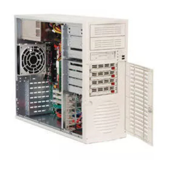
It provides information for the installation and use of the SuperWorkstation 7033A-T. formed by experienced technicians only. The SuperWorkstation 7033A-T is a high-end, dual processor tower server based on the SC733T-450 workstation/server chassis and the X5DAL-TG2, a dual processor motherboard that supports single or dual Intel Xeon cessors up to 3.06 GHz at a Front Side (System) Bus speed of 533/400... - Page 4 You should thoroughly familiarize yourself with this chapter for a general overview of safety precautions that should be followed when installing and servicing the SuperWorkstation 7033A-T. Chapter 5: Advanced Motherboard Setup Chapter 5 provides detailed information on the X5DAL-TG2 motherboard, including the locations and functions of connections, headers and jumpers.
- Page 5 Preface Notes...
-
Page 6: Table Of Contents
Manual Organization ... iii Chapter 1: Introduction Overview ... 1-1 Server Chassis Features ... 1-2 Mainboard Features ... 1-3 Contacting Supermicro ... 1-5 Chapter 2: Server Installation Overview ... 2-1 Unpacking the 7033A-T ... 2-1 Preparing for Setup ... 2-1 Checking the Motherboard Setup ... - Page 7 Chapter 5: Advanced Motherboard Setup Handling the X5DAL-TG2 Motherboard ... 5-1 PGA Processor and Heatsink Installation ... 5-2 Connecting Cables ... 5-5 Connecting Data Cables ... 5-5 Connecting Power Cables ... 5-5 Connecting the Control Panel ... 5-6 I/O Ports ... 5-7 Installing Memory ...
- Page 8 UPER ORKSTATION 7033A-T Manual Jumper Settings ... 5-18 Explanation of Jumpers ... 5-18 CMOS Clear ... 5-18 System Bus Speed ... 5-18 GLAN Enable/Disable ... 5-19 Power Fail Alarm Enable/Disable ... 5-19 Watch Dog Enable/Disable ... 5-19 Thermal Fan Control ... 5-20 Serial ATA Enable/Disable ...
- Page 9 Table of Contents Appendices: Appendix A: BIOS POST Messages ... A - 1 Appendix B: BIOS POST Codes ... B-1 Appendix C: System Specifications ... C-1...
- Page 10 UPER ORKSTATION 7033A-T Manual Notes...
-
Page 11: Chapter 1: Introduction
SuperWorkstation 7033A-T. In addition to the motherboard and chassis, various hardware components have been included with the SuperWorkstation 7033A-T, as listed below: Two (2) CPU heatsinks (Fan-050-CFT) Two (2) heatsink retention clip assemblies (SKT-095-604E) One (1) 3.5"... -
Page 12: Chassis Features
Serial ATA drives. Front Control Panel The control panel of the SuperWorkstation 7033A-T provides you with sev- eral system monitoring and control functions. LEDs indicate system power, hard drive activity, network activity and overheat conditions. A main power button and a system reset button are also included on the front panel. -
Page 13: Motherboard Features
Motherboard Features At the heart of the SuperWorkstation 7033A-T lies the X5DAL-TG2, a dual processor motherboard designed to provide maximum performance. Below are the main features of the X5DAL-TG2. Processors The X5DAL-TG2 supports single or dual 604/603-pin Intel Xeon processors of up to 3.06 GHz with a 533/400 MHz FSB. - Page 14 UPER ORKSTATION 7033A-T Manual Onboard Controllers/Ports In addition to the Serial ATA controller, one floppy drive controller and an onboard ATA/100 controller (which supports up to four hard drives or ATAPI devices) are provided. The color-coded I/O ports include two COM ports, a parallel port, two USB ports, PS/2 mouse and keyboard ports and two G-bit Ethernet ports.
-
Page 15: Contacting Supermicro
Contacting Supermicro Headquarters Address: SuperMicro Computer, Inc. 980 Rock Ave. San Jose, CA 95131 U.S.A. Tel: +1 (408) 503-8000 Fax: +1 (408) 503-8008 Email: marketing@supermicro.com (General Information) support@supermicro.com (Technical Support) Web Site: www.supermicro.com Europe Address: SuperMicro Computer B.V. Het Sterrenbeeld 28, 5215 ML... - Page 16 UPER ORKSTATION 7033A-T Manual Notes...
-
Page 17: Chapter 2: Server Installation
Unpacking the 7033A-T You should inspect the box the SuperWorkstation 7033A-T was shipped in and note if it was damaged in any way. damage you should file a damage claim with the carrier who delivered it. -
Page 18: Server Precautions
UPER ORKSTATION 7033A-T Manual Server Precautions - Review the electrical and general safety precautions in Chapter 4. - Use a regulating uninterruptible power supply (UPS) to protect the server from power surges, voltage spikes and to keep your system operating in case of a power failure. Allow the hot plug Serial ATA drives and power supply unit(s) to cool before touching them. - Page 19 4. Installing add-on cards If desired, you can install add-on cards to the system. See Chapter 5 for details on installing PCI add-on cards. 5. Check all cable connections and airflow Make sure all power and data cables are properly connected and not blocking the chassis airflow.
-
Page 20: Checking The Drive Bay Setup
UPER ORKSTATION 7033A-T Manual Checking the Drive Bay Setup Next, you should check to make sure the peripheral drives and the Serial ATA drives and Serial ATA backplane have been properly installed and all connections have been made. 1. Accessing the drive bays All drives can be accessed from the front of the server. -
Page 21: Chapter 3: System Interface
Overview There are several LEDs on the control panel as well as two for each Serial ATA drive carrier and LAN (Ethernet) port. constantly informed of the overall status of the system and the activity and health of specific components. There are also two buttons on the chassis control panel. -
Page 22: Control Panel Leds
UPER ORKSTATION 7033A-T Manual Control Panel LEDs The control panel located on the front of the SC733T-450 chassis has six LEDs that provide you with critical information related to different parts of the system. This section explains what each LED indicates when illumi- nated and any corrective action you may need to take. -
Page 23: Serial Ata Drive Carrier Leds
Serial ATA Drive Carrier LEDs Each Serial ATA drive carrier has two LEDs. Green: When illuminated, the green LED on the front of the drive carrier indicates drive activity. enables this LED to blink on and off when that particular drive is being accessed. - Page 24 UPER ORKSTATION 7033A-T Manual Notes...
-
Page 25: Chapter 4: System Safety
Electrical Safety Precautions Basic electrical safety precautions should be followed to protect yourself from harm and the SuperWorkstation 7033A-T from damage: Be aware of the locations of the power on/off switch on the chassis as well as the room's emergency power-off switch, disconnection switch or electrical outlet. -
Page 26: General Safety Precautions
General Safety Precautions Follow these rules to ensure general safety: Keep the area around the SuperWorkstation 7033A-T clean and free of clutter. The SuperWorkstation 7033A-T weighs approximately 45 lbs. when fully loaded. When lifting the system, two people at either end should lift slowly with their feet spread out to distribute the weight. -
Page 27: Esd Safety Precautions
Remove any jewelry or metal objects from your body, which are excellent metal conductors that can create short circuits and harm you if they come into contact with printed circuit boards or areas where power is present. After accessing the inside of the system, close the system back up and after ensuring that all connections have been made. -
Page 28: Operating Precautions
UPER ORKSTATION 7033A-T Manual For grounding purposes, make sure your computer chassis provides excellent conductivity between the power supply, the case, the mounting fasteners and the motherboard. Operating Precautions Care must be taken to assure that all chassis covers are in place when the 7033A-T is operating to ensure proper cooling. -
Page 29: Chapter 5: Advanced Motherboard Setup
Advanced Motherboard Setup This chapter covers the steps required to install processors and heatsinks to the X5DAL-TG2 motherboard, connect the data and power cables and install add-on cards. scribed and a layout and quick reference chart are included in this chapter. Remember to close the chassis completely when you have finished working on the motherboard to protect and cool the system sufficiently. -
Page 30: Pga Processor And Heatsink Installation
UPER ORKSTATION 7033A-T Manual PGA Processor and Heatsink Installation When handling the processor package, avoid placing direct pressure on the label area of the fan. Also, do not place the motherboard on a conductive surface, which can damage the BIOS battery and prevent the system from booting up. IMPORTANT: Always connect the power cord last and always remove it before adding, removing or changing any hardware components. - Page 31 5. Secure the heatsink by locking the retention clips into their proper posi- tion. When correctly installed, the retention clips should *click* into place and the three black tabs on the CPU retention pieces should protrude fully through the corresponding holes on the retention clips. and 5-2b for diagrams of the retention clips and the heatsink installation procedure.
- Page 32 UPER ORKSTATION 7033A-T Manual Figure 5-2a. Retention Clips (left: 603-pin, right: 604-pin) Figure 5-2b. Heatsink Installation...
-
Page 33: Connecting Cables
Connecting Cables Now that the processors are installed, the next step is to connect the cables to the board. These include the data (ribbon) cables for the periph- erals and control panel and the power cables. Connecting Data Cables The ribbon cables used to transfer data from the peripheral devices have been carefully routed in preconfigured systems to prevent them from block- ing the flow of cooling air that moves through the system from front to back. -
Page 34: Connecting The Control Panel
UPER ORKSTATION 7033A-T Manual Connecting the Control Panel JF2 contains header pins for various front control panel connectors. Figure 5-3 for the pin locations of the various front control panel buttons and LED indicators. Please note that even and odd numbered pins are on opposite sides of each header. -
Page 35: I/O Ports
Keyboard USB Ports (Purple) Installing Memory Note: Check the Supermicro web site for recommended memory modules: http://www.supermicro.com/TECHSUPPORT/FAQs/Memory_vendors.htm Exercise extreme care when installing or removing DIMM modules to prevent any possible damage. Also note that the memory is interleaved to improve performance (see step 1). - Page 36 UPER ORKSTATION 7033A-T Manual Memory Support The X5DAL-TG2 supports up to 8 GB of registered ECC or unbuffered DDR- 266/200 (PC2100/1600) memory. This product was designed to support 2 GB modules in each slot, but it has only been verified for up to 1 GB modules.
-
Page 37: Adding Pci Cards
Chapter 5: Advanced Motherboard Setup Adding PCI Cards 1. PCI slots: The X5DAL-TG2 has one 64-bit 100 MHz PCI-X slot, one 64-bit 66 MHz PCI slot and two 32-bit 33 MHz PCI slots. One 8xAGP slot (for video cards) is also included. -
Page 38: X5Dal-Tg2 Layout
UPER ORKSTATION 7033A-T Manual Motherboard Details Figure 5-7. SUPER X5DAL-TG2 Layout JPUSB Keyboard D3, D4 JPWAKE Mouse USB0/1 COM1 CPU 1 CPU Fan1 COM2 GLAN1 CPU 2 GLAN2 CPU Fan2 Overheat Fan 8xAGP (1.5V) JP38 33 MHz PCI #2 33 MHz PCI #1 100 MHz PCI-X #2 1 2 3 4 5 6 7 8 9 0 1 2 3 4 5 6 7 8 9 0 1 2 3 JPL1... -
Page 39: X5Dal-Tg2 Quick Reference
X5DAL-TG2 Quick Reference Jumper Description JBT1 CMOS Clear Power Fail Alarm En/Disable JP37 Watch Dog JP38 Thermal Fan Control JP39 System (Front Side) Bus Speed Pins 1-2 (Auto) JPA1 SATA #1/#2 Enable/Disable JPA2 SATA #3/#4 Enable/Disable JPL1 GLAN Enable/Disable JPUSB USB Wake-up JPWAKE Keyboard Wake-up... -
Page 40: Connector Definitions
UPER ORKSTATION 7033A-T Manual Connector Definitions ATX Power Connector The main power supply connector on the X5DAL-TG2 meets the SSI (Superset ATX) 24-pin specifica- tion, however it also supports a 20-pin power supply connector. Make sure that the orientation of the connector is correct. -
Page 41: Hdd Led
HDD LED The HDD LED connection (for IDE drives) is located on pins 13 and 14 of JF2. Attach the hard drive LED cable here to display disk ac- tivity. See the table on the right for pin definitions. NIC1 LED The NIC (Network Interface Con- troller) LED connection for the GLAN1 port is located on pins 11... -
Page 42: Reset Button
UPER ORKSTATION 7033A-T Manual Reset Button The Reset Button connection is lo- cated on pins 3 and 4 of JF2. At- tach it to the hardware reset switch on the computer case. Refer to the table on the right for pin definitions. -
Page 43: Front Panel Universal Serial Bus Headers
Front Panel Universal Serial Bus Headers Extra USB headers (FPUSB0/ FPUSB1/FPUSB2/FPUSB3) can be used for front side USB access. You will need a USB cable to use either connection. Refer to the tables on the right for pin defini- tions. Serial Ports The COM1 and COM2 serial ports are located under the parallel port... -
Page 44: Fan Headers
Speaker Connector Pin Definitions (JD1) Number Function T hird Power Supply Fail Header Pin Definitions (JP8) Number Note: This feature is only available when using redundant Supermicro power supplies. This 5-16 Definition Ground (black) +12V (red) Tachometer Definition Red wire, Speaker data... -
Page 45: Wake-On-Lan
Wake-On-LAN The Wake-On-LAN header is des- ignated WOL. See the table on the right for pin definitions. You must enable the LAN Wake-Up setting in BIOS to use this feature. must also have a LAN card with a Wake-on-LAN connector cable. -
Page 46: Jumper Settings
UPER ORKSTATION 7033A-T Manual Jumper Settings Explanation of Jumpers To modify the operation of the motherboard, jumpers can be used choose optional settings. create shorts between two pins to change the function of the connector. Pin 1 is identified with a square solder pad on the printed circuit board. -
Page 47: Glan Enable/Disable
GLAN Enable/Disable Change the setting of jumper JPL1 to enable or disable both GLAN ports on the motherboard. See the table on the right for jumper set- tings. The default setting is en- abled. Power Fail Alarm Enable/ Disable The system can notify you in the event of a power supply failure. -
Page 48: Thermal Fan Control
UPER ORKSTATION 7033A-T Manual Thermal Fan Control Depending on the system tempera- ture, the thermal fan can run at two speeds (12V and 9V levels). JP38 open, the speed of this fan will change according to the tempera- ture sensed by hardware control. When closed, the fan will always run at full (12V) speed (this is the default setting). -
Page 49: 5-10 Onboard Indicators
5-10 Onboard Indicators GLAN LEDs Both Gb LAN ports (located beside the COM2 port) each have two LEDs. The yellow LED indicates activity while the other LED may be green, orange or off to indicate the speed of the connection. See the table at right for the functions associated with the second LED. -
Page 50: Parallel Port And Floppy/Hard Drive Connections
UPER ORKSTATION 7033A-T Manual 5-11 Parallel Port and Floppy/Hard Disk Drive Connections Note the following when connecting the floppy and hard disk drive cables: • The floppy disk drive cable has seven twisted wires. • A red mark on a wire typically designates the location of pin 1. •... -
Page 51: Floppy Connector
Floppy Connector The floppy connector is located on JP7. See the table below for pin definitions. IDE Connectors There are no jumpers to configure the onboard IDE#1 and #2 connectors (at J2 and J3, respectively). the table on the right for pin definitions. -
Page 52: 5-12 Installing Software Drivers
5-12 Installing Software Drivers After all the hardware has been installed you must install the software drivers. The necessary drivers are all included on the Supermicro CD that came packaged with your motherboard. CD-ROM drive, the display shown in Figure 5-8 should appear. -
Page 53: Chapter 6: Advanced Chassis Setup
Advanced Chassis Setup This chapter covers the steps required to install components and perform simple maintenance on the SC733T-450 chassis. Following the component installation steps in the order given will eliminate most common problems. If some steps are unnecessary, skip ahead to the next step. Tools Required The only tool you will need is a Philips screwdriver. -
Page 54: Front Control Panel
UPER ORKSTATION 7033A-T Manual Front Control Panel The front control panel must be connected to the JF2 connector on the motherboard to provide you with system status and alarm indications. ribbon cable has bundled these wires together to simplify this connection. Connect the cable from JF2 on the motherboard (making sure the red wire plugs into pin 1) to the appropriate comnnector on the front control panel PCB (printed circuit board). - Page 55 Chapter 6: Advanced Chassis Setup Figure 6-2. Chassis Front View 5 1/4" Drive Bays Floppy Drive Bay Main Power System Reset Front Side USB System LEDs SATA Active LED SATA Drive Configuration Drive IDs are marked on the Front Bezel Lock front bezel.
- Page 56 UPER ORKSTATION 7033A-T Manual Figure 6-3. Power Supply Fan IO Backplane PCI Expansion Slots Chassis Rear View Power Supply Alarm Reset Button 12-cm Exhaust Fan...
-
Page 57: System Fans
(see Figure 6-4). Installing a new system fan Replace the failed fan with an identical one (available from Supermicro). After the new fan has been installed, reassemble the fan housing and plug the housing back into its slot. You should hear it click into place when fully inserted. -
Page 58: Drive Bay Installation
UPER ORKSTATION 7033A-T Manual Figure 6-4. Drive Bay Installation A bezel covers the front of the chassis but does not need to be removed to access the drives. three tabs on the inside left side lip of the front chassis cover. slightly swing out the same (left) side of the cover - about ½... - Page 59 Installing/removing hot-plug SATA drives: The seven SATA drive carriers are all easily accessible at the front of the chassis. The SATA drives are hot-pluggable, meaning they can be removed and installed without powering down the system. To remove a carrier, first open the front bezel then push the release button located beside the drive LEDs.
- Page 60 UPER ORKSTATION 7033A-T Manual SATA backplane: All four SATA drives plug into the SATA backplane. There are two jumpers and two headers on the SATA backplane, as noted below. A ribbon cable from JA1 on the motherboard should be connected to the JP26 connector on the SATA backplane.
-
Page 61: Installing Components In The 5 1/4" Drive Bays
Installing Components in the 5.25" Drive Bays Drive bay configuration The 7033A-T has two 5.25" drive bays above the SATA drive bays. Components such as a floppy drive, IDE hard drives or CD-ROM drives can be installed in these 5.25" drive bays. Mounting components in the drive bays First power down the system and then remove the top/left chassis cover to access the drive components. -
Page 62: Power Supply
UPER ORKSTATION 7033A-T Manual Power Supply The 7033A-T has a single 450W redundant cooling power supply that fea- tures noise-suppression technology for silent operation. The power supply has the capability to automatically sense and operate from 100 to 240V AC. This power supply also has the PFC (Power Factor Correction) feature built Power Supply Failure If the primary power supply fan fails an audible alarm will notify you of a... -
Page 63: Chapter 7: Bios
Please refer Manual Download <http://www.supermicro.com> for any changes to BIOS that may not be reflected in this manual. System BIOS The BIOS is the Basic Input Output System used in all IBM ®... -
Page 64: Running Setup
UPER ORKSTATION 7033A-T Manual Running Setup *Default settings are in bold text unless otherwise noted. The BIOS setup options described in this section are selected by choos- ing the appropriate text from the main BIOS Setup screen. All displayed text is described in this section, although the screen display is often all you need to understand how to set the options (see on next page). -
Page 65: Phoenix Bios Setup Utility
Main BIOS Setup Menu Main Advanced System Time System Date Legacy Diskette A: Legacy Diskette B: Primary Master Primary Slave Secondary Master Secondary Slave System Memory Extended Memory ↑↓ F1 Help Select Item ↔ Esc Exit Select Menu Main Setup Features System Time To set the system date and time, key in the correct information in the appropriate fields. -
Page 66: Legacy Diskette A
UPER ORKSTATION 7033A-T Manual Legacy Diskette A This setting allows the user to set the type of floppy disk drive installed as diskette A. The options are Disabled, 360Kb 5.25 in, 1.2MB 5.25 in, 720Kb 3.5 in, 1.44/1.25MB, 3.5 in and 2.88MB 3.5 in. Legacy Diskette B This setting allows the user to set the type of floppy disk drive installed as diskette B. - Page 67 Type Selects the type of IDE hard drive. The options are Auto (allows BIOS automatically determine the hard drive's capacity, number of heads, etc.), a number from 1-39 to select a predetermined type of hard drive, CD-ROM and ATAPI Removable. Multi-Sector Transfers Select the number of transfer sectors.
-
Page 68: Advanced Setup
UPER ORKSTATION 7033A-T Manual Advanced Setup Choose Advanced from the Phoenix BIOS Setup Utility main menu with the arrow keys. You should see the following display. The items with a triangle beside them have sub menus that can be accessed by highlighting the item and pressing <Enter>. - Page 69 ACPI Mode Use the setting to determine if you want to employ ACPI (Advanced Configuration and Power Interface) power management on your system. Options are Yes and No. ACPI Sleep Mode Selects the sleep mode for ACPI. Options are S1 and S3. Power Loss Control This setting allows you to choose how the system will react when power returns after an unexpected loss of power.
- Page 70 UPER ORKSTATION 7033A-T Manual PCI/PnP Configuration Access the submenu to make changes to the following settings. Onboard LAN OPROM Configure Enabling this option provides the ability to boot from LAN. The options are Enabled and Disabled. Reset Configuration Data If set to Yes, this setting clears the Extended System Configuration Data area.
- Page 71 Latency Timer This setting allows you to set the minimum guaranteed time slot allotted for the bus master in units of PCI bus clocks. Options are Default, 0020h, 0040h, 0060h, 0080h, 00A0h, 00C0h and 00E0h. Advanced Chipset Control Access the submenu to make changes to the following settings. Graphics Aperture This setting allows you to set the aperture for the AGP video device.
- Page 72 UPER ORKSTATION 7033A-T Manual Legacy USB Support This setting allows you to enable support for Legacy USB devices. The settings are Enabled and Disabled. Local Bus IDE Adapter Use this setting to enable the integrated local bus IDE adapter. Options are Disable, Primary, Secondary and Both.
- Page 73 Mode Specify the type of device that will be connected to serial port B. Options are Normal and IR (for an infrared device). Base I/O Address Select the base I/O address for serial port B. The options are 3F8, 2F8, 3E8 and 2E8. Interrupt Select the IRQ (interrupt request) for serial port B.
- Page 74 UPER ORKSTATION 7033A-T Manual Floppy Disk Controller This setting allows you to assign control of the floppy disk controller. The options are Enabled (user defined), Disabled and Auto (BIOS controlled). Base I/O Address Select the base I/O address for the parallel port. The options are Primary and Secondary.
- Page 75 Chapter 7: BIOS Hyper-threading This setting allows you to Enable or Disable hyper-threading. Enabling hyper-threading results in increased CPU performance. DMI Event Logging Access the submenu to make changes to the following settings. Event Log Validity This is a display, not a setting, informing you of the event log validity. Event Log Capacity This is a display, not a setting, informing you of the event log capacity.
- Page 76 UPER ORKSTATION 7033A-T Manual Console Redirection Access the submenu to make changes to the following settings. COM Port Address Specifies to redirect the console to On-board COMA or On-board COMB. This setting can also be Disabled. BAUD Rate Select the BAUD rate for console redirection. Options are 300, 1200, 2400, 9600, 19.2K, 38.4K, 57.6K and 115.2K.
- Page 77 Chapter 7: BIOS System Temperature CPU Fan1 CPU Fan2 Chassis Fan 1 Chassis Fan 2 Processor Vcore 3.3V Standby 3.3V Vcc 5V Vcc 12V Vcc 1.8V Vcc -12V Vcc 7-15...
-
Page 78: Security
UPER ORKSTATION 7033A-T Manual Security Choose Security from the Phoenix BIOS Setup Utility main menu with the arrow keys. You should see the following display. displayed by highlighting the setting using the arrow keys and pressing <Enter>. All Security BIOS settings are described in this section. Main Advanced Supervisor Password Is:... - Page 79 Chapter 7: BIOS Set Supervisor Password When the item "Set Supervisor Password" is highlighted, hit the <Enter> key. When prompted, type the Supervisor's password in the dialogue box to set or to change supervisor's password, which allows access to BIOS. Set User Password When the item "Set User Password"...
-
Page 80: Boot
UPER ORKSTATION 7033A-T Manual Boot Choose Boot from the Phoenix BIOS Setup Utility main menu with the arrow keys. You should see the following display. Highlighting a setting with a + or - will expand or collapse that entry. See details on how to change the order and specs of boot devices in the Item Specific Help window. -
Page 81: Exit
Exit Choose Exit from the Phoenix BIOS Setup Utility main menu with the arrow keys. You should see the following display. All Exit BIOS settings are described in this section. Main Advanced Exit Saving Changes Exit Discarding Changes Load Setup Defaults Discard Changes Save Changes ↑↓... - Page 82 UPER ORKSTATION 7033A-T Manual Discard Changes Highlight this item and hit <Enter> to discard (cancel) any changes you made. You will remain in the Setup utility. Save Changes Highlight this item and hit <Enter> to save any changes you made. You will remain in the Setup utility.
-
Page 83: Appendix A: Bios Post Messages
Appendix A: BIOS POST Messages Appendix A BIOS POST Messages During the Power-On Self-Test (POST), the BIOS will check for problems. If a problem is found, the BIOS will activate an alarm or display a message. The following is a list of such BIOS messages. - Page 84 UPER ORKSTATION 7033A-T Manual System CMOS checksum bad - Default configuration used System CMOS has been corrupted or modified incorrectly, perhaps by an application program that changes data stored in CMOS. The BIOS installed Default Setup Values. If you do not want these values, enter Setup and enter your own values.
- Page 85 Appendix A: BIOS POST Messages System cache error - Cache disabled RAM cache failed and BIOS disabled the cache. On older boards, check the cache jumpers. You may have to replace the cache. See your dealer. A disabled cache slows system performance considerably. CPU ID: CPU socket number for Multi-Processor error.
- Page 86 UPER ORKSTATION 7033A-T Manual Fixed Disk n Fixed disk n (0-3) identified. Invalid System Configuration Data Problem with NVRAM (CMOS) data. I/O device IRQ conflict I/O device IRQ conflict error. PS/2 Mouse Boot Summary Screen: PS/2 Mouse installed. nnnn kB Extended RAM Passed Where nnnn is the amount of RAM in kilobytes successfully tested.
- Page 87 Appendix A: BIOS POST Messages Parity Check 2 nnnn Parity error found in the I/O bus. BIOS attempts to locate the address and display it on the screen. If it cannot locate the address, it displays ????. Press <F1> to resume, <F2> to Setup, <F3> for previous Displayed after any recoverable error message.
- Page 88 UPER ORKSTATION 7033A-T Manual Notes...
-
Page 89: Appendix B: Bios Post Codes
BIOS POST Codes This section lists the POST (Power On Self Test) codes for the PhoenixBIOS. POST codes are divided into two categories: recoverable and terminal. Recoverable POST Errors When a recoverable type of error occurs during POST, the BIOS will display an POST code that describes the problem. - Page 90 UPER ORKSTATION 7033A-T Manual POST Code Description Initialize keyboard controller 1-2-2-3 BIOS ROM checksum Initialize cache before memory Auto size 8254 timer initialization 8237 DMA controller initialization Reset Programmable Interrupt Controller 1-3-1-1 Test DRAM refresh 1-3-1-3 Test 8742 Keyboard Controller Set ES segment register to 4 GB Auto size DRAM Initialize POST Memory Manager...
- Page 91 POST Code Description Initialize POST display service Display prompt “Press F2 to enter SETUP” Disable CPU cache Test RAM between 512 and 640 kB Test extended memory Test extended memory address lines Jump to UserPatch1 Configure advanced cache registers Initialize Multi Processor APIC Enable external and CPU caches Setup System Management Mode (SMM) area Display external L2 cache size...
- Page 92 UPER ORKSTATION 7033A-T Manual POST Code Description Fix up Multi Processor table 1-2 Search for option ROMs. One long, two short beeps on checksum failure Check for SMART Drive (optional) Shadow option ROMs Set up Power Management Initialize security engine (optional) Enable hardware interrupts Determine number of ATA and SCSI drives Set time of day...
- Page 93 POST Code Description Redirect Int 13h to Memory Technologies Devices such as ROM, RAM, PCMCIA, and serial disk Redirect Int 10h to enable remote serial video Re-map I/O and memory for PCMCIA Initialize digitizer and display message Unknown interrupt The following are for boot block in Flash ROM POST Code Description Initialize the chipset...
- Page 94 UPER ORKSTATION 7033A-T Manual Notes...
-
Page 95: Appendix C: System Specifications
System Specifications Processors Single or dual 604/603-pin Intel front side (system) bus speed of 533/400 MHz Note: Please refer to the support section of our web site for a complete listing of supported processors. (http://www.supermicro.com/TechSupport.htm) Chipset Intel E7505 chipset BIOS ®... - Page 96 UPER ORKSTATION 7033A-T Manual System Input Requirements AC Input Voltage: 100-240V AC Rated Input Current: 7A (115V) to 4A (230V) Rated Input Frequency: 50 to 60 Hz BTU Rating 2825 BTUs/hr (for rated output power of 450W) Power Supply Rated Output Power: 450W (Model# SP450-RP, Part# PWS-045) Rated Output Voltages: +3.3V (30A), +5V (26A), +12V (30A), -5V (0.5A), -12V (1A), +5Vsb (2A) Operating Environment...
- Page 97 Appendix C: System Specifications Regulatory Compliance Electromagnetic Emissions: FCC Class B, EN 55022 Class B, EN 61000-3-2/3-3, CISPR 22 Class B Electromagnetic Immunity: EN 55024/CISPR 24, (EN 61000-4-2, EN 61000-4-3, EN 61000-4-4, EN 61000-4-5, EN 61000-4-6, EN 61000-4-8, EN 61000-4-11) Safety: EN 60950/IEC 60950-Compliant, UL Listed (USA), CUL Listed (Canada), TUV Certified (Germany), CE Marking (Europe)
- Page 98 UPER ORKSTATION 7033A-T Manual Notes...
Need help?
Do you have a question about the SuperWorkstation 7033A-T and is the answer not in the manual?
Questions and answers