
Related Manuals for Supero SuperWorkstation 7045A-C3


Summary of Contents for Supero SuperWorkstation 7045A-C3
- Page 1 UPER ® 7045A-C3 uper orkstation 7045A-CT uper orkstation USER’S MANUAL...
- Page 2 Please Note: For the most up-to-date version of this manual, please see our web site at www.supermicro.com. Super Micro Computer, Inc. ("Supermicro") reserves the right to make changes to the product described in this manual at any time and without notice. This product, including software, if any, and documentation may not, in whole or in part, be copied, photocopied, reproduced, translated or reduced to any medium or machine without prior written consent.
-
Page 3: Manual Organization
SuperWorkstation 7045A- C3/7045A-CT. Installation and maintenance should be performed by experienced technicians only. The SuperWorkstation 7045A-C3/7045A-CT is a high-end server based on the SC743TQ-865-SQ tower/4U rackmount chassis and the X7DCA-3/X7DCA- i, a dual processor serverboard that supports dual Intel 5400/5300/5200/5100 series processors. - Page 4 You should thoroughly familiarize yourself with this chapter for a general overview of safety precautions that should be followed when installing and servicing the SuperWorkstation 7045A-C3/7045A-CT. Chapter 5: Advanced Serverboard Setup Chapter 5 provides detailed information on the X7DCA-3/X7DCA-i serverboard, including the locations and functions of connections, headers and jumpers.
- Page 5 Preface Notes...
-
Page 6: Table Of Contents
SAS Subsystem ... 1-3 SATA Subsystem ... 1-3 Front Control Panel ... 1-3 I/O Backplane ... 1-4 Cooling System ... 1-4 Contacting Supermicro ... 1-6 Chapter 2 Server Installation Overview ... 2-1 Unpacking the System ... 2-1 Preparing for Setup ... 2-1 Choosing a Setup Location ... - Page 7 Installing the Rack Rails ... 2-6 Installing the Server into the Rack ... 2-7 Checking the Serverboard Setup ... 2-8 Checking the Drive Bay Setup ... 2-9 Chapter 3 System Interface Overview ... 3-1 Control Panel Buttons ... 3-1 Power ... 3-1 Reset ...
- Page 8 uper orkstation 7045A-C3/7045A-CT User's Manual X7DCA-3/X7DCA-i Quick Reference ... 5-13 Connector Defi nitions ... 5-14 5-10 Jumper Settings ... 5-21 5-11 Onboard Indicators ... 5-23 5-12 Parallel, Floppy, IDE, and SATA Ports ... 5-24 Chapter 6 Advanced Chassis Setup Static-Sensitive Devices ... 6-1 Precautions ...
-
Page 9: Chapter 1 Introduction
SuperWorkstation 7045A-C3/7045A-CT (www.supermicro.com). In addition to the serverboard and chassis, various hardware components have been included with the SuperWorkstation 7045A-C3/7045A-CT, as listed below: Two (2) 8-cm hot-swap PWM "SuperQuiet" chassis fans (FAN-0104L4) One (1) 9-cm PWM "SuperQuiet" exhaust fan (FAN-0103L4) Two (2) CPU heat sinks (SNK-P0034AP4) One (1) 3.5"... -
Page 10: Serverboard Features
7045A-C3/7045A-CT User's Manual Serverboard Features At the heart of the SuperWorkstation 7045A-C3/7045A-CT lies the X7DCA- 3/X7DCA-i, a dual processor serverboard based on the Intel 5100 chipset and designed to provide maximum performance. Below are the main features of the X7DCA-3/X7DCA-i. -
Page 11: Onboard Controllers/Ports
Front Control Panel The control panel on the SuperWorkstation 7045A-C3/7045A-CT provides you with system monitoring and control. LEDs indicate system power, HDD activity, network activity, overheat conditions and power supply failure. A main power button and a system reset button are also included. -
Page 12: I/O Backplane
uper orkstation 7045A-C3/7045A-CT User's Manual I/O Backplane The SC743TQ-865-SQ is an ATX form factor chassis that can be used as a tower or mounted in a 4U rackmount confi guration. The I/O backplane provides seven expansion slots, two COM ports, a parallel port, four USB 2.0 ports, PS/2 mouse and keyboard ports, two Gigabit Ethernet port(s) and 7.1 HDA ports. - Page 13 Figure 1-1. Intel 5100 Chipset: System Block Diagram Note: This is a general block diagram. Please see Chapter 5 for details. PCI-Exp x16 PCI-Exp x4 Ports #0~3 Ports PCI-Exp x4 LSI 1068 #4~7 to PCIE or SAS 133/100MHz PCI-Exp x4 PCI-X PXH-V PCI-X...
-
Page 14: Contacting Supermicro
Super Micro Computer, Inc. 980 Rock Ave. San Jose, CA 95131 U.S.A. Tel: +1 (408) 503-8000 Fax: +1 (408) 503-8008 Email: marketing@supermicro.com (General Information) support@supermicro.com (Technical Support) Web Site: www.supermicro.com Europe Address: Super Micro Computer B.V. Het Sterrenbeeld 28, 5215 ML... -
Page 15: Chapter 2 Server Installation
If the server itself shows damage you should fi le a damage claim with the carrier who delivered it. Decide on a suitable location for the SuperWorkstation 7045A-C3/7045A-CT. It should be situated in a clean, dust-free area that is well ventilated. Avoid areas where heat, electrical noise and electromagnetic fi... -
Page 16: Choosing A Setup Location
uper orkstation 7045A-C3/7045A-CT User's Manual Choosing a Setup Location • Leave enough clearance in front of the rack to enable you to open the front door completely (~25 inches) and approximately 30 inches of clearance in the back of the rack to allow for suffi cient airfl ow and ease in servicing. •... -
Page 17: Rack Mounting Considerations
• Allow the hot plug SAS/SATA drives and power supply modules to cool before touching them. • Always keep the rack's front door and all panels and components on the servers closed when not servicing to maintain proper cooling. Rack Mounting Considerations Ambient Operating Temperature If installed in a closed or multi-unit rack assembly, the ambient operating tempera- ture of the rack environment may be greater than the ambient temperature of the... -
Page 18: Installing The System Into A Rack
uper orkstation 7045A-C3/7045A-CT User's Manual Installing the System into a Rack This section provides information on installing the system into a rack unit. Rack installation requires the use of the optional rackmount kit. If the system has already been mounted into a rack or if you are using it as a tower, you can skip ahead to Sections 2-5 and 2-6. -
Page 19: Installing The Chassis Rails
Chapter 2: Server Installation Installing the Chassis Rails You will need to remove the top cover and the feet to add rack rails to the chassis. First, remove the top and right covers (top and left covers when standing as a tower chassis) by fi... -
Page 20: Installing The Rack Rails
Figure 2-3. Installing the Rails to the Chassis Installing the Rack Rails Determine where you want to place the SuperWorkstation 7045A-C3/7045A-CT in the rack. (See Rack and Server Precautions in Section 2-3.) Position the fi xed rack rail/sliding rail guide assemblies at the desired location in the rack, keeping the sliding rail guide facing the inside of the rack. -
Page 21: Installing The Server Into The Rack
Chapter 2: Server Installation Installing the Server into the Rack You should now have rails attached to both the chassis and the rack unit. The next step is to install the server into the rack. You should have two brackets in the rack mount kit. -
Page 22: Checking The Serverboard Setup
uper orkstation 7045A-C3/7045A-CT User's Manual Checking the Serverboard Setup After setting up the the system, you will need to open the unit to make sure the serverboard is properly installed and all the connections have been made. Accessing the Inside of the System If rack mounted, fi... -
Page 23: Checking The Drive Bay Setup
Figure 2-5. Accessing the Inside of the System (Rack Confi guration shown) Checking the Drive Bay Setup Next, you should check to make sure the peripheral drives and the SAS/SATA drives and backplane have been properly installed and all connections have been made. - Page 24 uper orkstation 7045A-C3/7045A-CT User's Manual Depending upon your system's confi guration, your system may have one or more drives already installed. If you need to install SAS/SATA drives, please refer to Chapter 6. Checking the Airfl ow Airfl ow is provided by four hot-swap 8-cm chassis fans working in conjunction with an air shroud.
-
Page 25: Chapter 3 System Interface
System Interface Overview The control panel on the 7045A-C3/7045A-CT has several LEDs and two buttons. There are also two LEDs on each SAS/SATA drive carrier. These LEDs keep you constantly informed of the overall status of the system and the activity and health of specifi... -
Page 26: Control Panel Leds
uper orkstation 7045A-C3/7045A-CT User's Manual Control Panel LEDs The control panel located on the front of the SC743TQ-865-SQ chassis has six LEDs that provide you with critical information related to different parts of the system. This section explains what each LED indicates when illuminated and any corrective action you may need to take. -
Page 27: Power Fail
airfl ow in the system or the ambient room temperature being too warm. Check the routing of the cables and make sure all fans are present and operating normally. You should also check to make sure that the chassis covers are installed. Finally, verify that the heatsinks are installed properly (see Chapter 5). - Page 28 uper orkstation 7045A-C3/7045A-CT User's Manual Notes...
-
Page 29: Chapter 4 System Safety
Electrical Safety Precautions Basic electrical safety precautions should be followed to protect yourself from harm and the SuperWorkstation 7045A-C3/7045A-CT from damage: • Be aware of the locations of the power on/off switch on the chassis as well as the room's emergency power-off switch, disconnection switch or electrical outlet. -
Page 30: General Safety Precautions
Contact technical support for details and support. General Safety Precautions Follow these rules to ensure general safety: • Keep the area around the SuperWorkstation 7045A-C3/7045A-CT clean and free of clutter. • The 7045A-C3/7045A-CT weighs approximately 64 lbs (29.1 kg.) when fully loaded. -
Page 31: Esd Precautions
• After accessing the inside of the system, close the system back up and secure it to the rack unit with the retention screws after ensuring that all connections have been made. ESD Precautions Electrostatic discharge (ESD) is generated by two objects with different electrical charges coming into contact with each other. -
Page 32: Operating Precautions
uper orkstation 7045A-C3/7045A-CT User's Manual Operating Precautions Care must be taken to assure that the chassis cover is in place when the 7045A- C3/7045A-CT is operating to assure proper cooling. Out of warranty damage to the 7045A-C3/7045A-CT system can occur if this practice is not strictly followed. Figure 4-1. -
Page 33: Chapter 5 Advanced Serverboard Setup
Advanced Serverboard Setup This chapter covers the steps required to install the X7DCA-3/X7DCA-i serverboard into the chassis, connect the data and power cables and install add-on cards. All serverboard jumpers and connections are also described. A layout and quick refer- ence chart are included in this chapter for your reference. -
Page 34: Unpacking
The X7DCA-3/X7DCA-i requires a chassis big enough to support a 12" x 13" serverboard, such as Supermicro's SC743TQ-865-SQ. Make sure that the I/O ports on the serverboard align properly with their respective holes in the I/O shield at the back of the chassis. -
Page 35: Connecting Data Cables
Connecting Data Cables The cables used to transfer data from the peripheral devices have been carefully routed to prevent them from blocking the fl ow of cooling air that moves through the system from front to back. If you need to disconnect any of these cables, you should take care to keep them routed as they were originally after reconnecting them (make sure the red wires connect to the pin 1 locations). -
Page 36: I/O Ports
uper orkstation 7045A-C3/7045A-CT User's Manual Figure 5-1. Control Panel Header Pins Ground Power On LED HDD LED NIC1 LED NIC2 LED OH/Fan Fail LED Power Fail LED Ground Ground I/O Ports The I/O ports are color coded in conformance with the PC 99 specifi cation. See Figure 5-2 below for the colors and locations of the various I/O ports. -
Page 37: Installing The Processor And Heat Sink
Installing the Processor and Heat Sink Avoid placing direct pressure to the top of the processor package. Always remove the power cord fi rst before adding, removing or changing any hardware components. Notes: Always connect the power cord last and remove it before adding, remov- ing or changing any components. - Page 38 uper orkstation 7045A-C3/7045A-CT User's Manual CPU Installation A black PnP cap is attached to the load plate to protect the CPU socket. Press the load lever down and away from the retention clasp to release the load plate from its locked position.
- Page 39 With the CPU in the socket, in- spect the four corners of the CPU to make sure that it is properly installed. Use your thumb to gently push the load lever down until it snaps into the retention clasp. If the CPU is properly installed into the socket, the PnP cap will be automatically released from the load plate when the lever locks.
- Page 40 uper orkstation 7045A-C3/7045A-CT User's Manual Installation and Removal of the Heat Sink Installing the Heat Sink Installation Do not apply any thermal grease to the heat sink or the CPU die; the required amount has already been applied. Place the heatsink on top of the CPU so that the four mounting holes are aligned with those on the retention mechanism.
-
Page 41: Installing Memory
Installing Memory CAUTION! Exercise extreme care when installing or removing DIMM modules to prevent any possible damage. Installing Memory Modules Insert the desired number of DIMMs into the memory slots. The memory scheme is interleaved, so you must install two modules at a time, beginning with DIMM 1A and DIMM 1B, then DIMM 2A and DIMM 2B and fi... - Page 42 uper orkstation 7045A-C3/7045A-CT User's Manual Possible System Memory Allocation & Availability System Device Firmware Hub fl ash memory (System BIOS) Local APIC Area Reserved for the chipset I/O APIC (4 Kbytes) PCI Enumeration Area 1 PCI Express (256 MB) PCI Enumeration Area 2 (if needed) -Aligned on 256-MB boundary- VGA Memory TSEG...
-
Page 43: Adding Pci Cards
Adding PCI Cards The X7DCA-3/X7DCA-i has one PCI-Express x16 slot, one PCI-Express x4 slot (in a x16 slot), two 64-bit 133/100 MHz PCI-X slots and two PCI 33 MHz slots. The SC743TQ-865-SQ chassis can accommodate up to seven PCI expansion cards. PCI cards are installed directly to the serverboard. -
Page 44: Serverboard Details
uper orkstation 7045A-C3/7045A-CT User's Manual Serverboard Details Figure 5-4. X7DCA-3/X7DCA-i Layout Note: the X7DCA-i shares the same layout as the X7DCA-3 but has no SAS com- ponents or connectors. (not drawn to scale) 5-12... -
Page 45: X7Dca-3/X7Dca-I Quick Reference
X7DCA-3/X7DCA-i Quick Reference Jumper Description JBT1 CMOS Clear C1/JI C to PCI-X Slots C3/JI C to PCI-E Slots JPL1/JPL2 LAN1/2 Enable/Disable JWD1 Watch Dog Connector Description Audio High Defi nition Audio (HDA) Jacks CD1/JC2 Audio Headers (see Section 5-9) COM1/COM2 COM1 Serial Ports FAN 1-8 Chassis/CPU Fan Headers... -
Page 46: Connector Defi Nitions
uper orkstation 7045A-C3/7045A-CT User's Manual Connector Defi nitions Main ATX Power Supply Connector The primary power supply connector (JPW3) meets the SSI (Superset ATX) 24-pin specifi cation. Refer to the table on the right for the pin defi nitions of the ATX 24-pin power connector. - Page 47 Reset Connector The reset connector is located on pins 3 and 4 of JF1 and attaches to the reset switch on the computer chas- sis. See the table on the right for pin defi nitions. Power Fail LED The Power Fail LED connection is located on pins 5 and 6 of JF1.
- Page 48 uper orkstation 7045A-C3/7045A-CT User's Manual HDD LED The HDD LED connection is located on pins 13 and 14 of JF1. This LED is used to display all IDE and SATA activity. See the table on the right for pin defi nitions. Power On LED The Power On LED connector is lo- cated on pins 15 and 16 of JF1 (use...
- Page 49 Chassis Intrusion The Chassis Intrusion header is des- ignated JL1. Attach an appropriate cable from the chassis to inform you of a chassis intrusion when the chas- sis is opened Wake-On-LAN The Wake-On-LAN header is des- ignated JWOL1 on the serverboard. See the table on the right for pin defi...
- Page 50 uper orkstation 7045A-C3/7045A-CT User's Manual Overheat LED/Fan Fail (JOH1) The JOH1 header is used to connect an LED to provide warning of chassis overheating. This LED will blink to in- dicate a fan failure. Refer to the table on right for pin defi nitions. Power LED/Speaker On JD1 header, pins 1-3 are for a power LED and pins 4-7 are for the...
- Page 51 ATX PS/2 Keyboard and PS/2 Mouse Ports The ATX PS/2 keyboard and the PS/2 mouse are located beside the USB0/1 ports. The mouse port is above the keyboard port. See the table on the right for pin defi nitions. Power SMB (I C) Connector The power SMB (I C) connector is...
- Page 52 uper orkstation 7045A-C3/7045A-CT User's Manual CD Header A 4-pin CD header (CD1) and a Front Panel Audio header (JC2) are included on the serverboard. These headers allow you to use the on- board sound for audio CD playback. Connect an audio cable from your CD drive to the CD header that fi...
-
Page 53: 5-10 Jumper Settings
5-10 Jumper Settings Explanation of Jumpers To modify the operation of the serverboard, jumpers can be used to choose between optional settings. Jumpers create shorts between two pins to change the function of the con- nector. Pin 1 is identifi ed with a square solder pad on the printed circuit board. - Page 54 uper orkstation 7045A-C3/7045A-CT User's Manual LAN1/2 Enable/Disable Change the setting of jumper JPL1 and JPL2 to enable or disable the LAN1 and LAN2 Ethernets port, respectively. See the table on the right for jumper set- tings. The default setting is enabled. C Bus to PCI-X/ Slots Jumpers JI C1 and JI...
-
Page 55: 5-11 Onboard Indicators
5-11 Onboard Indicators LAN1/2 LEDs The Ethernet ports (located beside the VGA port) have two LEDs. On each port, one LED indicates activity while the other LED may be green, amber or off to indicate the speed of the connection. See the table on the right for the functions associated with the connection speed LED. -
Page 56: 5-12 Parallel, Floppy, Ide, And Sata Ports
uper orkstation 7045A-C3/7045A-CT User's Manual 5-12 Parallel, Floppy, IDE, and SATA Ports Use the following information to connect the IDE hard disk drive cables. • A red mark on a wire typically designates the location of pin 1. • The 80-wire ATA100/66 IDE hard disk drive cable that came with your system has two connectors to support two drives. - Page 57 IDE Connector There is a single IDE connector on the serverboard. See the table on the right for pin defi nitions. SATA Ports There are no jumpers to confi gure the onboard SATA connectors. See the table on the right for pin defi ni- tions.
- Page 58 uper orkstation 7045A-C3/7045A-CT User's Manual Floppy Drive Connector The fl oppy connector is designated "Floppy". See the table below for pin defi nitions. Floppy Drive Connector Pin Defi nitions (Floppy) Pin# Defi nition Pin # Ground FDHDIN Ground Reserved FDEDIN Ground Index Ground...
-
Page 59: Chapter 6 Advanced Chassis Setup
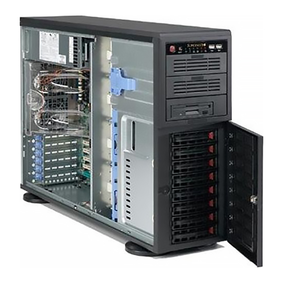
Advanced Chassis Setup This chapter covers the steps required to install components and perform simple maintenance on the SC743TQ-865-SQ chassis. Following the component installa- tion steps in the order given will eliminate most common problems. If some steps are unnecessary, skip ahead to the step that follows. Refer to Chapter 2 for instructions on installing the system as a 4U rackmount. - Page 60 uper orkstation 7045A-C3/7045A-CT User's Manual Figure 6-1. Chassis Front View Main Power System Reset USB Ports 5.25" Drive Bays (2) Floppy Drive 8 SAS/SATA Drive Bays (behind locking bezel)
-
Page 61: Front Control Panel
Front Control Panel The front control panel must be connected to the JF1 connector on the serverboard to provide you with system status and alarm indications. A ribbon cable has bundled these wires together to simplify this connection. Connect the cable from JF1 on the serverboard (making sure the red wire plugs into pin 1) to the appropriate comnnector on the front control panel PCB (printed circuit board). -
Page 62: System Fans
Installing a New Fan Replace the failed fan with an identical one (available from Supermicro) Install it in the same position and orientation as the one you removed; it should click into place when fully inserted. - Page 63 Chapter 6: Advanced Chassis Setup Figure 6-3. Removing a Chassis Fan...
-
Page 64: Drive Bay Installation
uper orkstation 7045A-C3/7045A-CT User's Manual Drive Bay Installation A total of eight SAS (or six SATA) drives may be housed in the SC743TQ-865-SQ chassis. The drive IDs are preconfi gured as 0 through 7 (or 5) in order from bot- tom to top (or from left to right if rackmounted). -
Page 65: Sas/Sata Backplane
Figure 6-4. Removing a SAS/SATA Drive Carrier Figure 6-5. Mounting a SAS/SATA Drive in a Carrier Important! Use extreme caution when working around the SAS/ SATA backplane. Do not touch the backplane with any metal objects and make sure no ribbon cables touch the backplane or obstruct the airfl... -
Page 66: Installing Components In The 5.25" Drive Bays
uper orkstation 7045A-C3/7045A-CT User's Manual Installing Components in the 5.25" Drive Bays The 7045A-C3/7045A-CT has two 5.25" drive bays. Components such as an extra fl oppy drive, IDE hard drives or CD-ROM drives can be installed into these 5.25" drive bays. Removing the Empty Drive Bay First power down the system. -
Page 67: Power Supply
Replace with the same model - PWS-865-PQ, which can be ordered directly from Supermicro (see Contact Information in the Preface). As there is only one power supply unit, the server must be powered down before removing and/or replacing the power supply for whatever reason. - Page 68 uper orkstation 7045A-C3/7045A-CT User's Manual Notes 6-10...
-
Page 69: Chapter 7 Bios
Note: Due to periodic changes to the BIOS, some settings may have been added or deleted and might not yet be recorded in this manual. Please refer to the Manual Download area of the Supermicro web site for any changes to the BIOS that may not be refl ected in this manual. -
Page 70: Running Setup
uper orkstation 7045A-C3/7045A-CT User's Manual Running Setup Default settings are in bold text unless otherwise noted. The BIOS setup options described in this section are selected by choosing the ap- propriate text from the main BIOS Setup screen. All displayed text is described in this section, although the screen display is often all you need to understand how to set the options (see the next page). -
Page 71: Main Bios Setup Menu
Chapter 7: BIOS Main BIOS Setup Menu Main Setup Features System Time To set the system date and time, key in the correct information in the appropriate fi elds. Then press the <Enter> key to save the data. System Date Using the arrow keys, highlight the month, day and year fi... - Page 72 uper orkstation 7045A-C3/7045A-CT User's Manual IDE Primary Master/Slave, IDE Secondary Master/Slave, SATA Port3, SATA Port4 and Ext. Primary Master/Slave These settings allow the user to set the parameters of IDE Primary Master/Slave, IDE Secondary Master/Slave, SATA Port 3, SATA Port 4 and Ext. Primary Master/ Slave.
- Page 73 CHS Format (Available for Primary/Master only) The following items will be displayed by the BIOS: Type: This item displays the type of IDE or SATA Device. Cylinders: This item indicates the status of Cylinders. Headers: This item indicates the number of headers. Sectors: This item displays the number of sectors.
- Page 74 uper orkstation 7045A-C3/7045A-CT User's Manual Serial ATA This setting allows the user to enable or disable the Serial ATA function. The options are Disabled and Enabled. Native Mode Operation Select the native mode for ATA. The options are Parallel ATA, Serial ATA, Both and Auto.
-
Page 75: Advanced Setup
Chapter 7: BIOS Advanced Setup Choose Advanced from the Phoenix BIOS Setup Utility main menu with the ar- row keys. You should see the following display. The items with a triangle beside them have sub menus that can be accessed by highlighting the item and pressing <Enter>. -
Page 76: Memory Cache
uper orkstation 7045A-C3/7045A-CT User's Manual ACPI Sleep Mode UThis feature allows you to decide which ACPI power management mode to use when in sleep mode. The options are S1, S3 and S1S3. Power Button Behavior If set to Instant-Off, the system will power off immediately as soon as the user hits the power button. - Page 77 Chapter 7: BIOS will be reserved for Video BIOS ROM access only. Select Uncached to disable this function and make this area available for other devices. Cache Base 0-512K If enabled, this feature will allow the data stored in the base memory area: block 0-512K to be cached (written) into a buffer, a storage area in the Static DROM (SDROM) or to be written into the L1, L2 cache inside the CPU to speed up CPU operations.
-
Page 78: Pci Configuration
uper orkstation 7045A-C3/7045A-CT User's Manual graphic effects when using a Linux graphic driver that requires the write-combining confi guration with 4GB or more memory. The options are Enabled and Disabled. PCI Confi guration Access the submenu to make changes to the following settings for PCI devices. Onboard GLAN1/Onboard GLAN2 (Gigabit- LAN) OPROM Confi... -
Page 79: Advanced Chipset Control
Advanced Chipset Control Access the submenu to make changes to the following settings. Warning : Use caution when changing the Advanced settings. Incorrect setup, a very high DRAM frequency or an incorrect DRAM timing may cause the sys- tem become unstable. If this occurs, reset the stting to the default setting. Crystal Beach Features Select Enabled to use Intel's I/O AT (Acceleration Technology) to accelerate the performance of TOE devices. -
Page 80: Advanced Processor Options
uper orkstation 7045A-C3/7045A-CT User's Manual USB Host Controller 2 Select Enabled to activate USB Host Controller 2. The settings are Enabled and Disabled. Legacy USB Support This setting allows you to enable support for Legacy USB devices. The settings are Enabled and Disabled. Advanced Processor Options Access the submenu to make changes to the following settings. - Page 81 Chapter 7: BIOS Execute Disable Bit (Available when supported by the CPU and the OS) Set to Enabled to enable Execute Disable Bit and allow the processor to classify areas in memory where an application code can execute and where it cannot, and thus preventing a worm or a virus from inserting and creating a fl...
-
Page 82: I/O Device Configuration
uper orkstation 7045A-C3/7045A-CT User's Manual CPU Cache Control Access the submenu to make changes to the following settings. Direct Cache Access (Available when supported by the CPU) Set to Enable to route inbound network IO traffi c directly into processor caches to reduce memory latency and improve network performance. -
Page 83: Dmi Event Logging
Chapter 7: BIOS Base I/O Address This setting allows you to select the base I/O address for serial port B. The options are 3F8, 2F8, 3E8 and 2E8. Interrupt This setting allows you to select the IRQ (interrupt request) for serial port B. The options are IRQ3 and IRQ4. -
Page 84: Console Redirection
uper orkstation 7045A-C3/7045A-CT User's Manual Event Log Validity This is a display to inform you of the event log validity. It is not a setting. Event Log Capacity This is a display to inform you of the event log capacity. It is not a setting. View DMI Event Log Highlight this item and press <Enter>... -
Page 85: Hardware Monitor Logic
Chapter 7: BIOS Console Connection This item allows you to decide how the console redirection is to be connected: either Direct or Via Modem. Continue CR after POST This item allows you to decide whether you want to continue with the console redirection after POST routines. - Page 86 uper orkstation 7045A-C3/7045A-CT User's Manual Voltage Monitoring The following items will be monitored and displayed: Vcore A, Vcore B, -12V, +12V, P1V5, +3.3V, 5Vsb, 5VDD, P_VTT and Vbat Note: In a Windows OS environment, the Supero Doctor III settings take prece- dence over the BIOS settings.
-
Page 87: System Event Log/System Event Log (List Mode)
Existing Event Log Number This item displays the number of the existing event log. Event Log Control System Firmware Progress Enable this function to log the POST progress. The options are Enabled and Disabled. BIOS POST Errors Enabling this function to log POST errors. The options are Enabled and Dis- abled. -
Page 88: Realtime Sensor Data
uper orkstation 7045A-C3/7045A-CT User's Manual Realtime Sensor Data This feature display information from motherboard sensors, such as temperatures, fan speeds and voltages of various components. 7-20... -
Page 89: Security
Chapter 7: BIOS Security Choose Security from the Phoenix BIOS Setup Utility main menu with the arrow keys. You should see the following display. Security setting options are displayed by highlighting the setting using the arrow keys and pressing <Enter>. All Security BIOS settings are described in this section. - Page 90 uper orkstation 7045A-C3/7045A-CT User's Manual Set User Password When the item Set User Password is highlighted, hit the <Enter> key. When prompted, type the user's password in the dialogue box to set or to change the user's password, which allows access to the system at boot-up. Password on Boot This setting allows you to determine if a password is required for a user to enter the system at bootup.
-
Page 91: Boot
Boot Choose Boot from the Phoenix BIOS Setup Utility main menu with the arrow keys. You should see the following display. See details on how to change the order and specs of boot devices in the Item Specifi c Help window. All Boot BIOS settings are described in this section. -
Page 92: Exit
uper orkstation 7045A-C3/7045A-CT User's Manual Exit Choose Exit from the Phoenix BIOS Setup Utility main menu with the arrow keys. You should see the following display. All Exit BIOS settings are described in this section. Exit Saving Changes Highlight this item and hit <Enter> to save any changes you made and to exit the BIOS Setup utility. -
Page 93: Appendix A Bios Post Messages
Appendix A: BIOS POST Messages Appendix A BIOS POST Messages During the Power-On Self-Test (POST), the BIOS will check for problems. If a problem is found, the BIOS will activate an alarm or display a message. The fol- lowing is a list of such BIOS messages. Failure Fixed Disk Fixed disk is not working or not confi... - Page 94 uper orkstation 7045A-C3/7045A-CT User's Manual System CMOS checksum bad - Default confi guration used System CMOS has been corrupted or modifi ed incorrectly, perhaps by an applica- tion program that changes data stored in CMOS. The BIOS installed Default Setup Values.
- Page 95 Appendix A: BIOS POST Messages slows system performance considerably. CPU ID: CPU socket number for Multi-Processor error. EISA CMOS not writeable ServerBIOS2 test error: Cannot write to EISA CMOS. DMA Test Failed ServerBIOS2 test error: Cannot write to extended DMA (Direct Memory Access) registers.
- Page 96 uper orkstation 7045A-C3/7045A-CT User's Manual I/O device IRQ confl ict I/O device IRQ confl ict error. PS/2 Mouse Boot Summary Screen: PS/2 Mouse installed. nnnn kB Extended RAM Passed Where nnnn is the amount of RAM in kilobytes successfully tested. nnnn Cache SRAM Passed Where nnnn is the amount of system cache in kilobytes successfully tested.
- Page 97 Appendix A: BIOS POST Messages screen (usually an initialization error of an Option ROM, i.e., an add-on card). Write down and follow the information shown on the screen. Press <F2> to enter Setup Optional message displayed during POST. Can be turned off in Setup. PS/2 Mouse: PS/2 mouse identifi...
- Page 98 uper orkstation 7045A-C3/7045A-CT User's Manual Notes...
-
Page 99: Recoverable Post Errors
Appendix B BIOS POST Codes This section lists the POST (Power On Self Test) codes for the PhoenixBIOS. POST codes are divided into two categories: recoverable and terminal. Recoverable POST Errors When a recoverable type of error occurs during POST, the BIOS will display an POST code that describes the problem. - Page 100 uper orkstation 7045A-C3/7045A-CT User's Manual POST Code Description 8254 timer initialization 8237 DMA controller initialization Reset Programmable Interrupt Controller 1-3-1-1 Test DRAM refresh 1-3-1-3 Test 8742 Keyboard Controller Set ES segment register to 4 GB Auto size DRAM Initialize POST Memory Manager Clear 512 kB base RAM 1-3-4-1 RAM failure on address line xxxx* 1-3-4-3 RAM failure on data bits xxxx* of low byte of...
- Page 101 POST Code Description Test RAM between 512 and 640 kB Test extended memory Test extended memory address lines Jump to UserPatch1 Confi gure advanced cache registers Initialize Multi Processor APIC Enable external and CPU caches Setup System Management Mode (SMM) area Display external L2 cache size Load custom defaults (optional) Display shadow-area message...
- Page 102 uper orkstation 7045A-C3/7045A-CT User's Manual POST Code Description Check for SMART Drive (optional) Set up Power Management Initialize security engine (optional) Enable hardware interrupts Determine number of ATA and SCSI drives Set time of day Check key lock Initialize typematic rate Erase <ESC>...
- Page 103 The following are for boot block in Flash ROM POST Code Description Initialize the chipset Initialize the bridge Initialize the CPU Initialize system timer Initialize system I/O Check force recovery boot Checksum BIOS ROM Go to BIOS Set Huge Segment Initialize Multi Processor Initialize OEM special code Initialize PIC and DMA...
- Page 104 uper orkstation 7045A-C3/7045A-CT User's Manual Notes...
-
Page 105: Appendix C Intel Hostraid Setup Guidelines
RAID Utility program to confi gure the RAID Level that you desire before installing the Windows XP/2000/2003 operating system and other software drivers. (The necessary drivers are all included on the Supermicro CD that came packaged with your motherboard.) Note: the current version of the ICH9R SATA RAID Utility can only support Windows XP/2000/2003 Operating Systems. -
Page 106: Raid Configurations
uper orkstation 7045A-C3/7045A-CT User's Manual RAID Confi gurations The following types of RAID confi gurations are supported: RAID 0 (Data Striping): this writes data in parallel, interleaved ("striped") sections of two hard drives. Data transfer rate is doubled over using a single disk. RAID 1 (Data Mirroring): an identical data image from one drive is copied to anoth- er drive. - Page 107 Using the Intel ICH9R SATA RAID Utility Program 1. Creating, Deleting and Resetting RAID Volumes: a. After the system exits from the BIOS Setup Utility, the system will automatically reboot. The following screen appears after Power-On Self Test. b. When you see the above screen, press the <Ctrl> and the <I> keys simultane- ously to have the main menu of the SATA RAID Utility appear: Note: All graphics and screen shots shown in the manual are for reference only.
-
Page 108: Creating A Raid 0 Volume
uper orkstation 7045A-C3/7045A-CT User's Manual Creating a RAID 0 Volume: a. Select "Create RAID Volume" from the main menu and press the <Enter> key. The following screen will appear: b. Specify a name for the RAID 0 set and press the <Tab> key or the <Enter> key to go to the next fi... -
Page 109: Creating A Raid 1 Volume
Appendix C: Intel HostRAID Setup Guidelines Creating a RAID 1 Volume: a. Select "Create RAID Volume" from the main menu and press the <Enter> key. The following screen will appear: b. Specify a name for the RAID 1 set and press the <Tab> key or the <Enter> key to go to the next fi... - Page 110 uper orkstation 7045A-C3/7045A-CT User's Manual Creating a RAID 10 (RAID 1+ RAID 0): a. Select "Create RAID Volume" from the main menu and press the <Enter> key. The following screen will appear: b. Specify a name for the RAID 10 set and press <Enter>. c.
-
Page 111: Creating A Raid 5 Set (Parity)
Appendix C: Intel HostRAID Setup Guidelines Creating a RAID 5 Set (Parity): a. Select "Create RAID Volume" from the main menu and press the <Enter> key. The following screen will appear: b. Specify a name for the RAID 5 set and press <Enter>. c. -
Page 112: Deleting Raid Volume
uper orkstation 7045A-C3/7045A-CT User's Manual Deleting RAID Volume: Warning: Be sure to back up your data before deleting a RAID set. You will lose all data on the disk drives when deleting a RAID set.) a. From the main menu, select item2-Delete RAID Volume, and press <Enter>. b. -
Page 113: Exiting The Intel Matrix Storage Manager Utility
Resetting to Non-RAID and Resetting a RAID HDD Warning: Be cautious when you reset a RAID volume HDD to non- RAID or Resetting a RAID HDD. Resetting a RAID volume HDD or Resetting a RAID HDD will reformat the HDD and delete all internal RAID structure on the drive. - Page 114 After the Windows XP/2000/2003 Installation is completed, the system will automatically reboot. i. Insert the Supermicro Setup CD that came with the package into the CD Drive during system reboot, and the main screen will appear. Note: the current version of the ICH9R SATA RAID Utility can only support the Windows XP/2000/2003 Operating System.
-
Page 115: Appendix D System Specifi Cations
Appendix D: System Specifi cations Appendix D System Specifi cations Processors Single or dual Intel® dual-core Xeon® 5400/5300/5200/5100 Sequence type processors at a front side (system) bus speed of 1333/1066 MHz Note: Please refer to our web site for a complete listing of supported processors. Chipset Intel 5100/ICH9R chipset BIOS... - Page 116 uper orkstation 7045A-C3/7045A-CT User's Manual Expansion Slots One PCI-Express x16, one PCI-Express x4 (in a x16 slot), two 64-bit 133/100 MHz PCI-X, two PCI 33 MHz and an IPMI slot Motherboard 7045A-C3: X7DCA-3 (Extended ATX form factor) 7045A-CT: X7DCA-i (Extended ATX form factor) Dimensions (both): 12 x 13 in (305 x 330 mm) Chassis SC743TQ-865-SQ Form Factor: tower/4U rackmount...
-
Page 117: Regulatory Compliance
Appendix D: System Specifi cations Regulatory Compliance Electromagnetic Emissions: FCC Class B, EN 55022 Class B, EN 61000-3-2/-3-3, CISPR 22 Class B Electromagnetic Immunity: EN 55024/CISPR 24, (EN 61000-4-2, EN 61000-4-3, EN 61000-4-4, EN 61000-4-5, EN 61000-4-6, EN 61000-4-8, EN 61000-4-11) Safety: EN 60950/IEC 60950-Compliant, UL Listed (USA), CUL Listed (Canada), TUV Certifi... - Page 118 uper orkstation 7045A-C3/7045A-CT User's Manual Notes...
Need help?
Do you have a question about the SuperWorkstation 7045A-C3 and is the answer not in the manual?
Questions and answers