
Subscribe to Our Youtube Channel
Related Manuals for Supero SuperWorkstation 7044A-8


Summary of Contents for Supero SuperWorkstation 7044A-8
- Page 1 UPER UPER ORKSTATION UPER ORKSTATION UPER ORKSTATION UPER ORKSTATION USER’S MANUAL 7044A-82 7044A-8 7044A-i2 7044A-i 1.0a ®...
- Page 2 The State of California, County of Santa Clara shall be the exclusive venue for the resolution of any such disputes. Supermicro's total liability for all claims will not exceed the price paid for the hardware product. Unless you request and receive written permission from SUPER MICRO COMPUTER, you may not copy any part of this document.
-
Page 3: About This Manual
About This Manual This manual is written for professional system integrators and PC technicians. It provides information for the installation and use of the SuperWorkstation 7044A- 82/7044A-8/7044A-i2/7044A-i. Installation and maintainance should be per- formed by experienced technicians only. The SuperWorkstation 7044A-82/7044A-8/7044A-i2/7044A-i is a high-end, dual processor workstation based on the SC743S1-645/SC743i-645 4U tower/ rackmount chassis and the X6DA8-G2/X6DA8-G/X6DAE-G2/X6DAE-G, a dual processor serverboard that supports single or dual Intel... - Page 4 UPER ORKSTATION 7044A-82/7044A-8/7044A-i2/7044A-i Manual Chapter 4: System Safety You should thoroughly familiarize yourself with this chapter for a general overview of safety precautions that should be followed when installing and servicing the SuperWorkstation 7044A-82/7044A-8/7044A-i2/7044A-i. Chapter 5: Advanced Serverboard Setup Chapter 5 provides detailed information on the X6DA8-G2/X6DA8-G/X6DAE-G2/ X6DAE-G serverboard, including the locations and functions of connections, headers and jumpers.
- Page 5 Preface Notes...
-
Page 6: Table Of Contents
Manual Organization ... iii Chapter 1: Introduction Overview ... 1-1 Serverboard Features ... 1-2 Server Chassis Features ... 1-3 Contacting Supermicro ... 1-6 Chapter 2: Quick Setup Overview ... 2-1 Unpacking the SuperWorkstation System ... 2-1 Preparing for Setup ... 2-1 Installing the System into a Rack ... - Page 7 Chapter 5: Advanced Serverboard Setup Handling the Serverboard ... 5-1 PGA Processor and Heatsink Installation ... 5-2 Connecting Cables ... 5-5 Connecting Data Cables ... 5-5 Connecting Power Cables ... 5-5 Connecting the Control Panel ... 5-6 I/O Ports ... 5-7 Installing Memory ...
- Page 8 UPER ORKSTATION 7044A-82/7044A-8/7044A-i2/7044A-i Manual CMOS Clear ... 5-18 GLAN Enable/Disable ... 5-19 SCSI Controller Enable/Disable ... 5-19 SCSI Termination Enable/Disable ... 5-19 Watch Dog Enable/Disable ... 5-20 AC'97 Audio Enable/Disable ... 5-20 Third Power Supply Alarm Enable/Disable ... 5-21 Power Force On Enable/Disable ... 5-21 5-10 Onboard Indicators ...
- Page 9 Table of Contents Appendices: Appendix A: BIOS POST Codes ... A-1 Appendix B: Software Installation ... B-1 Appendix C: System Specifications ... C-1...
- Page 10 UPER ORKSTATION 7044A-82/7044A-8/7044A-i2/7044A-i Manual Notes...
-
Page 11: Chapter 1: Introduction
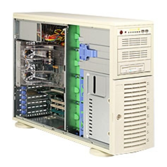
Overview The Supermicro SuperWorkstation 7044A-82/7044A-8/7044A-i2/7044A-i is a high-end dual processor workstation that can be utilized either in a tower or in a rackmount configuration. The 7044A-82/7044A-8/7044A-i2/7044A-i is com- prised of two main subsystems: the SC743S1-645/SC743i-645 high-end server chassis and the X6DA8-G2/X6DA8-G/X6DAE-G2/X6DAE-G dual Xeon sor serverboard. -
Page 12: Serverboard Features
The X6DA8-G2/X6DA8-G/X6DAE-G2/X6DAE-G supports single or dual 604-pin Intel Xeon processors at a FSB speed of 800 MHz. serverboard description pages on our web site for a complete listing of supported processors (http://www.supermicro.com). Memory The X6DA8-G2/X6DAE-G2 has eight 240-pin DIMM slots that can support up to 16 GB of registered ECC DDR2-400 (PC3200) SDRAM. -
Page 13: Server Chassis Features
Onboard Controllers/Ports One floppy drive controller and two onboard ATA/100 controllers are provided to support up to four hard drives or ATAPI devices. The color-coded I/O ports include two COM ports, a parallel port, four USB 2.0 ports, PS/2 mouse and keyboard ports and Line-In, Line-Out and Mic jacks. - Page 14 UPER ORKSTATION 7044A-82/7044A-8/7044A-i2/7044A-i Manual Front Control Panel The SuperWorkstation 7044A-82/7044A-8/7044A-i2/7044A-i's control panel pro- vides you with system monitoring and control. LEDs indicate system power, HDD activity, network activity, overheat condition and power supply failure. A main power button and a system reset button are also included. Note: the power supply fail LED is intended for use with redundant power supply systems and so is not needed for the 7044A-82/7044A-8/7044A-i2/7044A-i.
-
Page 15: System Block Diagram
Figure 1-1. Intel E7525 Chipset: Note: This is a general block diagram. Please see Chapter 5 for details. 1 PCI - X S L OT 1 J 12 1 PCI - X S L OT 2 J 13 S CS I PCI - X BUS ( 100 M HZ) 7902 PCI - X BUS ( 100 M HZ) -
Page 16: Contacting Supermicro
UPER ORKSTATION 7044A-82/7044A-8/7044A-i2/7044A-i Manual Contacting Supermicro Headquarters Address: SuperMicro Computer, Inc. 980 Rock Ave. San Jose, CA 95131 U.S.A. Tel: +1 (408) 503-8000 Fax: +1 (408) 503-8008 Email: marketing@supermicro.com (General Information) support@supermicro.com (Technical Support) Web Site: www.supermicro.com Europe Address: SuperMicro Computer B.V. -
Page 17: Server Installation
Server Installation 2-1 Overview This chapter provides a quick setup checklist to get your SuperWorkstation 7044A-82/7044A-8/7044A-i2/7044A-i up and running. Following these steps in the order given should enable you to have the system operational within a mini- mum amount of time. This quick setup assumes that your system has come to you with the processors and memory preinstalled. -
Page 18: Choosing A Setup Location
UPER ORKSTATION 7044A-82/7044A-8/7044A-i2/7044A-i Manual Choosing a Setup Location: - Leave enough clearance in front of the system to enable you to open the front door completely (~25 inches). - Leave approximately 30 inches of clearance in the back of the system to allow for sufficient airflow and ease in servicing. -
Page 19: Rack Mounting Considerations
Chapter 2: Server Installation Rack Mounting Considerations Ambient Operating Temperature If installed in a closed or multi-unit rack assembly, the ambient operating temperature of the rack environment may be greater than the ambient tem- perature of the room. Therefore, consideration should be given to installing the equipment in an environment compatible with the manufacturer’s maxi- mum rated ambient temperature (Tmra). -
Page 20: Installing The System Into A Rack
UPER ORKSTATION 7044A-82/7044A-8/7044A-i2/7044A-i Manual Installing the System into a Rack This section provides information on installing the system into a rack unit. Rack installation requires the use of the optional rackmount kit [CSE-PT26(B)]. If the system has already been mounted into a rack or if you are using it as a tower, you can skip ahead to Sections 2-5 and 2-6. -
Page 21: Installing The Chassis Rails
Chapter 2: Server Installation Installing the Chassis Rails: You will need to remove the top bezel cover and the feet to add rack rails to the chassis. First, remove the top and right covers (top and left covers when standing as a tower chassis) by first removing the screws that secure them to the chassis. -
Page 22: Installing The Rack Rails
UPER ORKSTATION 7044A-82/7044A-8/7044A-i2/7044A-i Manual Figure 2-3. Installing the Rails to the Chassis Installing the Rack Rails: Determine where you want to place the SuperWorkstation 7044A-82/7044A-8/ 7044A-i2/7044A-i in the rack. (See Rack and Server Precautions in Section 2- 3.) Position the fixed rack rail/sliding rail guide assemblies at the desired location in the rack, keeping the sliding rail guide facing the inside of the rack. -
Page 23: Installing The Server Into The Rack
Chapter 2: Server Installation Installing the Server into the Rack: You should now have rails attached to both the chassis and the rack unit. The next step is to install the server into the rack. You should have two brackets in the rack mount kit. -
Page 24: Checking The Serverboard Setup
UPER ORKSTATION 7044A-82/7044A-8/7044A-i2/7044A-i Manual Checking the Serverboard Setup After setting up the the system, you will need to open the unit to make sure the serverboard is properly installed and all the connections have been made. 1. Accessing the inside of the system (see Figure 2-5): (If rack mounted, first release the retention screws that secure the unit to the rack. -
Page 25: Checking The Drive Bay Setup
Checking the Drive Bay Setup Next, you should check to make sure the peripheral drives and the SCSI drives and SCA backplane have been properly installed and all connections have been made. (SCSI applies to 7044A-82/7044A-8 only.) 1. Accessing the drive bays: All drives can be accessed from the front of the server. - Page 26 UPER ORKSTATION 7044A-82/7044A-8/7044A-i2/7044A-i Manual 6. Supplying power to the system: The last thing you must do is to provide input power to the system. Plug the power cord from the power supply unit into a high-quality power strip that offers protection from electrical noise and power surges.
-
Page 27: Chapter 3: System Interface
Overview There are several LEDs on the control panel as well as two for each SCSI drive carrier (7044A-82/7044A-8 only) and the Ethernet port(s). These LEDs are to keep you constantly informed of the overall status of the system and the activity and health of specific components. -
Page 28: Control Panel Leds
UPER ORKSTATION 7044A-82/7044A-8/7044A-i2/7044A-i Manual Control Panel LEDs The control panel located on the front of the SC743S1-645/SC743i-645 chassis has six LEDs that provide you with critical information related to different parts of the system. This section explains what each LED indicates when illuminated and any corrective action you may need to take. -
Page 29: Power Fail
Power Fail: Indicates a power supply module has failed. This LED is inended for use with systems that have redundant power supply modules and therefore is not used with the SuperWorkstation 7044A-82/7044A-8/7044A-i2/ 7044A-i. SCSI Drive LEDs (7044A-82/7044A-8 only) Each SCSI drive carrier has two LEDs. Green: When illuminated, the green LED on the front of the SCSI drive carrier indicates drive activity. - Page 30 UPER ORKSTATION 7044A-82/7044A-8/7044A-i2/7044A-i Manual Notes...
-
Page 31: Chapter 4: System Safety
Electrical Safety Precautions Basic electrical safety precautions should be followed to protect yourself from harm and the SuperWorkstation 7044A-82/7044A-8/7044A-i2/7044A-i from damage: Be aware of the locations of the power on/off switch on the chassis as well as the room's emergency power-off switch, disconnection switch or electrical outlet. -
Page 32: General Safety Precautions
UPER ORKSTATION 7044A-82/7044A-8/7044A-i2/7044A-i Manual The power supply power cord must include a grounding plug and must be plugged into grounded electrical outlets. Serverboard Battery: CAUTION - There is a danger of explosion if the onboard battery is installed backwards, which will reverse its polarities. -
Page 33: Esd Safety Precautions
where power is present. After accessing the inside of the system, close the system back up and (if rackmounted) secure it to the rack unit with the retention screws after ensuring that all connections have been made. ESD Precautions Electrostatic discharge (ESD) is generated by two objects with different electrical charges coming into contact with each other. -
Page 34: Operating Precautions
UPER ORKSTATION 7044A-82/7044A-8/7044A-i2/7044A-i Manual For grounding purposes, make sure your computer chassis provides excellent conductivity between the power supply, the case, the mounting fasteners and the serverboard. Operating Precautions Care must be taken to assure that all chassis covers are in place when the SuperWorkstation 7044A-82/7044A-8/7044A-i2/7044A-i is operating to ensure proper cooling. -
Page 35: Chapter 5: Advanced Serverboard Setup
Advanced Serverboard Setup This chapter covers the steps required to install processors and heatsinks to the X6DA8-G2/X6DA8-G/X6DAE-G2/X6DAE-G serverboard, connect the data and power cables and install add-on cards. All serverboard jumpers and connections are described and a layout and quick reference chart are included in this chapter. Remember to close the chassis completely when you have finished working on the serverboard to protect and cool the system sufficiently. -
Page 36: Pga Processor And Heatsink Installation
UPER ORKSTATION 7044A-82/7044A-8/7044A-i2/7044A-i Manual PGA Processor and Heatsink Installation When handling the processor package, avoid placing direct pressure on the label area of the fan. Also, do not place the motherboard on a conductive surface, which can damage the BIOS battery and prevent the system from booting up. IMPORTANT: Always connect the power cord last and always remove it before adding, removing or changing any hardware components. - Page 37 Heatsink Installation* 1. Do not apply any thermal com- pound to the heatsink or the CPU die; the required amount has al- ready been applied. 2. Place the heatsink on top of the CPU so that the four mounting holes are aligned with those on the retention mechanism.
- Page 38 UPER ORKSTATION 7044A-82/7044A-8/7044A-i2/7044A-i Manual Removing the Heatsink/CPU IMPORTANT: Removal of the heatsink or the CPU is not recom- mended. However, if you do need to remove the heatsink, please follow the instructions below to prevent damaging the CPU or the CPU socket.
-
Page 39: Connecting Cables
Connecting Cables Now that the processors are installed, the next step is to connect the cables to the serverboard. These include the data (ribbon) cables for the peripherals and control panel and the power cables. Connecting Data Cables The ribbon cables used to transfer data from the peripheral devices have been carefully routed in preconfigured systems to prevent them from block- ing the flow of cooling air that moves through the system from front to back. -
Page 40: Connecting The Control Panel
UPER ORKSTATION 7044A-82/7044A-8/7044A-i2/7044A-i Manual Connecting the Control Panel JF1 contains header pins for various front control panel connectors. See Figure 5-2 for the pin locations of the various front control panel buttons and LED indicators. Please note that even and odd numbered pins are on opposite sides of each header. -
Page 41: I/O Ports
KB/Mouse *Note: The X6DA8-G and X6DAE-G have only a single LAN (Ethernet) port. Installing Memory Note: Check the Supermicro web site for recommended memory modules: http://www.supermicro.com/support/resources/ Exercise extreme care when installing or removing DIMM modules to prevent any possible damage. Also note that the memory is interleaved to improve performance (see step 1). - Page 42 UPER ORKSTATION 7044A-82/7044A-8/7044A-i2/7044A-i Manual Memory Support The X6DA8-G2/X6DAE-G2 has eight 240-pin DIMMs that support up to 16 GB of registered ECC DDR2-400 (PC3200) SDRAM memory. The X6DA8-G2/X6DAE- G2 was designed to support 4 GB modules in each slot, but has only been verified for up to 2 GB modules.
-
Page 43: Adding Pci Cards
Chapter 5: Advanced Serverboard Setup Adding PCI Cards 1. PCI slots: The X6DA8-G2/X6DA8-G/X6DAE-G2/X6DAE-G has has six PCI expansion slots, which includes one x16@4GB/sec PCI-Express slot, one x4@2GB/ sec PCI-Express slot, three 64-bit PCI-X slots (one 64-bit PCI-X 133 slot, one PCI-X 100 slot, one PCI-X 100MHz ZCR slot) and one 32-bit 33MHz PCI slot (w/PCI graphics card support). -
Page 44: X6Da8-G2/X6Da8-G/X6Dae-G2/X6Dae-G Layout
UPER ORKSTATION 7044A-82/7044A-8/7044A-i2/7044A-i Manual Serverboard Details Figure 5-6. SUPER X6DA8-G2/X6DA8-G/X6DAE-G2/X6DAE-G Layout* FAN6 J 3 2 FAN5 J 4 0 DIMM 1B USB0/1/ 2 / 3 DIMM 1A DIMM 2B COM1 DIMM 2A J 2 3 DIMM 3B DIMM 3A DIMM 4B DIMM 4A COM2 LAN1/2... -
Page 45: Quick Reference
X6DA8-G2/X6DA8-G/X6DAE-G2/X6DAE-G Jumper Description JBT1 CMOS Clear JP13 3rd Pwr Supply Alarm Enable/Disable Open (Disabled) JPA1* SCSI Controller Enable/Disable JPA2/JPA3* SCSI Ch. A/B Term. Enable/Disable JPC1 Audio Enable/Disable Power Force On JPL1 Giga-bit LAN Enable/Disable Watch Dog Enable Connector Description J1B4 Primary 24-pin ATX PWR Connector J1D1 12V 8-pin PWR Connector... -
Page 46: Connector Definitions
UPER ORKSTATION 7044A-82/7044A-8/7044A-i2/7044A-i Manual Connector Definitions ATX Power Connector The serverboard includes a 24-pin main power supply connector (J1B4) and a 4-pin CPU PWR connector (J32). These power connectors meet the SSI EPS 12V specification. You can use a 20-pin connector, but con- necting J3 is also required to ensure sufficient power. -
Page 47: Hdd Led
HDD LED The HDD LED (for IDE and SCSI Disk Drives) connection is located on pins 13 and 14 of JF1. Attach the hard drive LED cable to these pins to dis- play disk activity. Refer to the table on the right for pin definitions. NIC LEDs The NIC (Network Interface Control- ler) LED connections for the GLAN... -
Page 48: Reset Button
UPER ORKSTATION 7044A-82/7044A-8/7044A-i2/7044A-i Manual Reset Button The Reset Button connection is lo- cated on pins 3 and 4 of JF1. Attach it to the hardware reset switch on the computer case. Refer to the table on the right for pin definitions. Power Button The Power Button connection is lo- cated on pins 1 and 2 of JF1. -
Page 49: Fan Headers
Fan Headers There are eight fan headers (FAN1- FAN8) on the X6DA8-G2/X6DAE-G2. See the table on the right for pin defi- nitions. (Note: These fan headers are 4-pin fans. Pins 1-3 are backward compatible with traditional 3-pin fans.) Serial Ports The COM1 (J3) and COM2 (J4) serial ports are located under the parallel port (see Figure 2-3). -
Page 50: Power Led/Speaker/Nmi
UPER ORKSTATION 7044A-82/7044A-8/7044A-i2/7044A-i Manual Power LED/Speaker/NMI On the JDI header, pins 1-3 are for a power LED and pins 4-7 are for the speaker. See the table on the right for speaker pin definitions. Note: The speaker connector pins are for use with an external speaker. If you wish to use the onboard speaker, you should close pins 6-7 with a jumper. -
Page 51: Power Fault
Pin Definitions (JP12) Number P/S 1 Fail Signal P/S 2 Fail Signal P/S 3 Fail Signal Reset (from MB) Note: This feature is only available when using redundant Supermicro power supplies. Power Supply Fail Alarm Reset Pin Definitions (JP13) Number Con-... -
Page 52: Jumper Settings
UPER ORKSTATION 7044A-82/7044A-8/7044A-i2/7044A-i Manual Jumper Settings Explanation of Jumpers To modify the operation of the serverboard, jumpers can be used choose optional settings. create shorts between two pins to change the function of the connector. Pin 1 is identified with a square solder pad on the printed circuit board. -
Page 53: Glan Enable/Disable
GLAN Enable/Disable Change the setting of jumper JPL1 to enable or disable the onboard GLAN ports (GLAN1 and GLAN2) on the serverboard. See the table on the right for jumper settings. The default setting is enabled SCSI Controller Enable/ Disable (X6DA8-G2/X6DA8-G only) Jumper JPA1 allows you to enable or disable the SCSI headers. -
Page 54: Watch Dog Enable/Disable
UPER ORKSTATION 7044A-82/7044A-8/7044A-i2/7044A-i Manual Watch Dog Enable/Disable JWD enables the Watch Dog func- tion. Watch Dog is a system moni- tor that can reboot the system when a software application is "hung up". Pins 1-2 will cause WD to reset the system if an application is hung up. -
Page 55: Third Power Supply Alarm Enable/Disable
3rd Power Supply Alarm Enable/Disable The system can notify you in the event of a power supply failure. This feature assumes that three power supply units are installed in the chassis with one acting as a backup. If you only have one or two power supply units installed, you should disable this (the default set- ting) with JP14 to prevent false... -
Page 56: 5-10 Onboard Indicators
UPER ORKSTATION 7044A-82/7044A-8/7044A-i2/7044A-i Manual 5-10 Onboard Indicators GLAN1/GLAN2 LEDs Each of the Ethernet ports (located beside the VGA port) have two LEDs. The yellow LED indicates activity while the other LED may be green, orange or off to indicate the speed of the connection. See the table on the right for the func- tions associated with this second LED. -
Page 57: Floppy Connector
Floppy Connector The floppy connector is located on JP8. See the table below for pin definitions. IDE Connectors There are no jumpers to configure the onboard IDE#1 and #2 connectors. See the table on the right for pin definitions. Chapter 5: Advanced Serverboard Setup Floppy Connector Pin Definitions (JP8) Pin Number Function... -
Page 58: Ultra320 Scsi Connectors
UPER ORKSTATION 7044A-82/7044A-8/7044A-i2/7044A-i Manual Ultra320 SCSI Connectors (X6DA8-G2/X6DA8-G only) Refer to the table below for the pin defini- tions of the Ultra320 SCSI connectors lo- cated at JA1 and JA2. Connector Contact Number Ultra320 SCSI Connectors (JA1, JA2) Connector Contact Signal Names Number +DB(12) -
Page 59: Chapter 6: Advanced Chassis Setup
Advanced Chassis Setup This chapter covers the steps required to install components and perform simple maintenance on the SC743S1-645/SC743i-645 chassis. Following the compo- nent installation steps in the order given will eliminate most common problems. If some steps are unnecessary, skip ahead to the step that follows. Refer to Chapter 2 for instructions on installing the system as a 4U rackmount. - Page 60 UPER ORKSTATION 7044A-82/7044A-8/7044A-i2/7044A-i Manual Figure 6-1. Chassis Front View System LEDs USB Ports Main Power System Reset 5.25" Drive Bays (2) Floppy Drive 8 SCSI Drive Bays (7044A- 82/7044A-8 only) 2 IDE Drive Carriers, 4 hard drives each (7044A- i2/7044A-i only)
-
Page 61: Front Control Panel
Front Control Panel The front control panel must be connected to the JF1 connector on the serverboard to provide you with system status and alarm indications. A ribbon cable has bundled these wires together to simplify this connection. Connect the cable from JF1 on the serverboard (making sure the red wire plugs into pin 1) to the appropriate comnnector on the front control panel PCB (printed circuit board). -
Page 62: System Fans
Installing a new system fan: Replace the failed fan with an identical one (available from Supermicro). Install and reassemble it in the fan housing then plug the housing back into its slot; it should click into place when fully inserted. Check that the fan is working properly and replace the top/left side chassis panel. - Page 63 Chapter 6: Advanced Chassis Setup Figure 6-3. Removing a Chassis Fan Figure 6-4. Removing the Air Shroud...
-
Page 64: Drive Bay Installation
UPER ORKSTATION 7044A-82/7044A-8/7044A-i2/7044A-i Manual Drive Bay Installation SCSI Drives (7044A-82/7044A-8 only) Eight SCSI drives may be housed in the SC743S1-645chassis. The SCSI drive IDs are preconfigured as 0 through 7 in order from right to left (or from bottom to top if rackmounted). Note: You must use standard 1"... - Page 65 Figure 6-5. Removing a SCSI Drive Carrier Figure 6-6. Mounting a SCSI Drive in a Carrier Important: are installed, all SCSI drive carriers must remain in the drive bays to promote proper airflow. SCSI backplane: All eight SCSI drives plug into a single SCSI backplane, which provides Ultra320 single channel operation for all eight SCSI drives.
- Page 66 UPER ORKSTATION 7044A-82/7044A-8/7044A-i2/7044A-i Manual Figure 6-7. SCSI Backplane SCSI LVD Connector Power Connector Jumper Settings JP19: Buzzer Enable, Closed (On) Enabled (default), Open (Off): Disabled LEDs Drive Fail LEDs: Fail1, Fail2, Fail3, Fail4, Fail5, Fail6, Fail7, Fail8 Activity LEDs: ACT1, ACT2, ACT3, ACT4, ACT5, ACT6, ACT7, ACT8...
-
Page 67: Installing Components In The 5.25" Drive Bays
Installing Components in the 5.25" Drive Bays Drive bay configuration The 7044A-82/7044A-i2 has two 5.25" drive bays. Components such as an extra floppy drive, IDE hard drives or CD-ROM drives can be installed in these 5.25" drive bays. Mounting components in the drive bays First power down the system and then remove the top/left chassis cover to access the drive components. -
Page 68: Power Supply
If the power supply unit fails, the system will shut down and you will need to replace the unit. Replacement units can be ordered directly from Supermicro (see contact information in the Preface). As there is only one power supply... -
Page 69: Chapter 7: Bios
Note: Due to periodic changes to the BIOS, some settings may have been added or deleted and might not yet be recorded in this manual. Please refer to the Manual Download area of the Supermicro web site (http://www.supermicro.com) for any changes to the BIOS that may not be reflected in this manual. -
Page 70: Running Setup
UPER ORKSTATION 7044A-82/7044A-8/7044A-i2/7044A-i Manual Running Setup *Default settings are in bold text unless otherwise noted. The BIOS setup options described in this section are selected by choosing the appropriate text from the main BIOS Setup screen. All displayed text is described in this section, although the screen display is often all you need to understand how to set the options (see on next page). -
Page 71: Main Bios Setup Menu
Chapter 7: BIOS Main BIOS Setup Menu Main Setup Features System Time To set the system date and time, key in the correct information in the appropriate fields. Then press the <Enter> key to save the data. System Date Using the arrow keys, highlight the month, day and year fields and enter the correct data. - Page 72 UPER ORKSTATION 7044A-82/7044A-8/7044A-i2/7044A-i Manual Legacy Diskette A This setting allows the user to set the type of floppy disk drive installed as diskette A. The options are Disabled, 360Kb 5.25 in, 1.2MB 5.25 in, 720Kb 3.5 in, 1.44/1.25MB, 3.5 in and 2.88MB 3.5 in. Parallel ATA This setting allows the user to enable or disable the funciton of Parallel ATA.
- Page 73 Chapter 7: BIOS Type Selects the type of IDE hard drive. The options are Auto (allows the BIOS to automatically determine the hard drive's capacity, number of heads, etc.), a number from 1-39 to select a predetermined type of hard drive, CD-ROM and ATAPI Removable.
- Page 74 UPER ORKSTATION 7044A-82/7044A-8/7044A-i2/7044A-i Manual LBA Mode Control This item determines whether The Phoenix BIOS will access the IDEChannel 0 Master Device via the LBA mode. The options are Disabled and Enabled. 32 Bit I/O This option allows the user to enable or disable the function of 32-bit datea transfer.
-
Page 75: Advanced Setup
Advanced Setup Choose Advanced from the Phoenix BIOS Setup Utility main menu with the arrow keys. You should see the following display. The items with a triangle beside them have sub menus that can be accessed by highlighting the item and pressing <Enter>. - Page 76 UPER ORKSTATION 7044A-82/7044A-8/7044A-i2/7044A-i Manual ACPI Mode Use the setting to determine if you want to employ ACPI (Advanced Configuration and Power Interface) power management on your system. The options are Yes and No. ACPI Sleep Mode Selects the sleep mode for ACPI. The options are S1(-Stanby) and S3 (-Suspend to RAM).
- Page 77 Chapter 7: BIOS to enable the function and this area will be reserved for the BIOS ROM access only. Select "Uncached" to disable this function and make this area available for other devices. Cache Base 0-512K If enabled, this feature will allow the data stored in the base memory area: block 0-512K to be cached (written) into a buffer, a storage area in the Static DRM (SDROM) or written into L1, L2, L3 cache inside the CPU to speed up CPU operations .
- Page 78 UPER ORKSTATION 7044A-82/7044A-8/7044A-i2/7044A-i Manual 512K. Select "Write Back" to allow CPU to write data back directly from the buffer without writing data to the System Memory for fast CPU data processing and operation. The options are "Uncached", "Write Through", "Write Protect", and "Write Back". PCI Configuration Access the submenu to make changes to the following settings for PCI devices.
- Page 79 Option ROM Scan When enabled, this setting will initialize the device expansion ROM. The options are Enabled and Disabled. Enable Master This setting allows you to enable the selected device as the PCI bus master. The options are Enabled and Disabled. Latency Timer This setting allows you to set the clock rate for Bus Master.A high- prioity, high-throughout device may benefit from a greater Clock rate.
- Page 80 UPER ORKSTATION 7044A-82/7044A-8/7044A-i2/7044A-i Manual PCI-E Express Jitter Tolerance This feature allows the user to set the PCI-E Jitter Tolerance Level. options are: 4 to 12. PCI-E Port A Device 2/PCI-E Port B Device 4 If enabled, the feature allows you to set the device selected to be compliant with the PCI-Express Compliance 1.0 Mode.
- Page 81 Chapter 7: BIOS USB Device 29, Function 0 & 1 & 2 & 3 This setting allows you to Enable or Disable all functions for the USB devices specified. Legacy USB Support This setting allows you to enable support for Legacy USB devices. The settings are Enabled and Disabled.
- Page 82 UPER ORKSTATION 7044A-82/7044A-8/7044A-i2/7044A-i Manual I/O Device Configuration Access the submenu to make changes to the following settings. Serial Port A This setting allows you to assign control of serial port A. The options are Enabled (user defined), Disabled, Auto (BIOS controlled) and OS Controlled.
- Page 83 Interrupt Select the IRQ (interrupt request) for the parallel port. The options are IRQ5 and IRQ7. Mode Specify the parallel port mode. The options are Output, Bi-directional, ECP and EPP. DMA Channel Specify the DMA channel. The options are DMA1 and DMA3. Floppy Disk Controller This setting allows you to assign control of the floppy disk controller.
- Page 84 UPER ORKSTATION 7044A-82/7044A-8/7044A-i2/7044A-i Manual DMI Event Logging Access the submenu to make changes to the following settings. Event Log Validity This is a display, not a setting, informing you of the event log validity. Event Log Capacity This is a display, not a setting, informing you of the event log capacity. View DMI Event Log Highlight this item and press <Enter>...
- Page 85 Chapter 7: BIOS Console Redirection Access the submenu to make changes to the following settings. COM Port Address Specifies to redirect the console to On-board COM A or On-board COM B. This setting can also be Disabled. BAUD Rate Select the BAUD rate for console redirection. The options are 300, 1200, 2400, 9600, 19.2K, 38.4K, 57.6K and 115.2K.
- Page 86 UPER ORKSTATION 7044A-82/7044A-8/7044A-i2/7044A-i Manual Hardware Monitor Logic CPU Temperature Threshold This option allows the user to set a CPU temperature threshold that will activate the alarm system when the CPU temperature reaches this pre-set temperature threshold. The options are 70 C, 75 C, 80 C and...
-
Page 87: Security
Chapter 7: BIOS Security Choose Security from the Phoenix BIOS Setup Utility main menu with the arrow keys. You should see the following display. Security setting options are displayed by highlighting the setting using the arrow keys and pressing <Enter>. All Security BIOS settings are described in this section. - Page 88 UPER ORKSTATION 7044A-82/7044A-8/7044A-i2/7044A-i Manual Set Supervisor Password When the item "Set Supervisor Password" is highlighted, hit the <Enter> key. When prompted, type the Supervisor's password in the dialogue box to set or to change supervisor's password, which allows access to the BIOS. Set User Password When the item "Set User Password"...
-
Page 89: Boot
Chapter 7: BIOS Boot Choose Boot from the Phoenix BIOS Setup Utility main menu with the arrow keys. You should see the following display. Highlighting a setting with a + or - will expand or collapse that entry. See details on how to change the order and specs of boot devices in the Item Specific Help window. -
Page 90: Exit
UPER ORKSTATION 7044A-82/7044A-8/7044A-i2/7044A-i Manual Exit Choose Exit from the Phoenix BIOS Setup Utility main menu with the arrow keys. You should see the following display. All Exit BIOS settings are described in this section. Exit Saving Changes Highlight this item and hit <Enter> to save any changes you made and to exit the BIOS Setup utility. - Page 91 Chapter 7: BIOS Discard Changes Highlight this item and hit <Enter> to discard (cancel) any changes you made. You will remain in the Setup utility. Save Changes Highlight this item and hit <Enter> to save any changes you made. You will remain in the Setup utility.
- Page 92 UPER ORKSTATION 7044A-82/7044A-8/7044A-i2/7044A-i Manual Notes 7-24...
-
Page 93: Appendix A: Bios Post Codes
BIOS POST Codes This section lists the POST (Power On Self Test) codes for the PhoenixBIOS. POST codes are divided into two categories: recoverable and terminal. Recoverable POST Errors When a recoverable type of error occurs during POST, the BIOS will display an POST code that describes the problem. - Page 94 UPER ORKSTATION 7044A-82/7044A-8/7044A-i2/7044A-i Manual POST Code Description 8254 timer initialization 8237 DMA controller initialization Reset Programmable Interrupt Controller 1-3-1-1 Test DRAM refresh 1-3-1-3 Test 8742 Keyboard Controller Set ES segment register to 4 GB Auto size DRAM Initialize POST Memory Manager Clear 512 kB base RAM 1-3-4-1 RAM failure on address line xxxx* 1-3-4-3 RAM failure on data bits xxxx* of low byte of memory bus...
- Page 95 POST Code Description Test RAM between 512 and 640 kB Test extended memory Test extended memory address lines Jump to UserPatch1 Configure advanced cache registers Initialize Multi Processor APIC Enable external and CPU caches Setup System Management Mode (SMM) area Display external L2 cache size Load custom defaults (optional) Display shadow-area message...
- Page 96 UPER ORKSTATION 7044A-82/7044A-8/7044A-i2/7044A-i Manual POST Code Description Check for SMART Drive (optional) Shadow option ROMs Set up Power Management Initialize security engine (optional) Enable hardware interrupts Determine number of ATA and SCSI drives Set time of day Check key lock Initialize typematic rate Erase F2 prompt Scan for F2 key stroke...
- Page 97 POST Code Description Re-map I/O and memory for PCMCIA Initialize digitizer and display message Unknown interrupt The following are for boot block in Flash ROM POST Code Description Initialize the chipset Initialize the bridge Initialize the CPU Initialize system timer Initialize system I/O Check force recovery boot Checksum BIOS ROM...
- Page 98 UPER ORKSTATION 7044A-82/7044A-8/7044A-i2/7044A-i Manual Notes...
-
Page 99: Appendix B: Software Installation
After all the hardware has been installed, you must first configure the Adaptec Embedded Serial ATA RAID Driver before you install the Windows operating system. The necessary drivers are all included on the Supermicro bootable CDs that came packaged with your motherboard. - Page 100 UPER ORKSTATION 7044A-82/7044A-8/7044A-i2/7044A-i Manual Configuring BIOS for SATA RAID Functions 1. Press the <Del> key during system bootup to enter the BIOS Setup Utility. Note: If it is the first time to power on the system, we recommend that you load the Optimized Default Settings.
- Page 101 I/O throughput and providing data accessibility regardless of a single disk failure. By incorporating the Adaptec Embedded Serial ATA into the motherboard design, Supermicro's X6DA8-G2 offers the user with the benefits of SATARAID without the high costs associated with hardware RAID applications.
- Page 102 UPER ORKSTATION 7044A-82/7044A-8/7044A-i2/7044A-i Manual Managing Arrays Select this option to view array properties, and delete arrays. The following sections describe the operations Of "Managing Arrays". To select this option, use the arrow keys and the <enter> key to select "Managing Arrays" from the main menu (as shown above).
- Page 103 Viewing Array Properties To view the properties of an existing array: 1. At the BIOS prompt, press Ctrl+A. 2. From the ARC menu, select Array Configuration Utility (ACU). 3. From the ACU menu, select Manage Arrays (as shown on the previous screen.) 4.
- Page 104 UPER ORKSTATION 7044A-82/7044A-8/7044A-i2/7044A-i Manual Creating Arrays Before creating arrays, make sure the disks for the array are connected and installed in your system. Note that disks with no usable space, or disks that are un-initialized are shown in gray and cannot be used.
- Page 105 Appendix B: Software Installation Assigning Array Properties Once you've create a new array, you are ready to assign the properties to the array. *Caution: Once the array is created and its properties are assigned, you cannot change the array properties using the ACU. You will need to use the Adaptec Storage Manager - Browser Edition.
- Page 106 UPER ORKSTATION 7044A-82/7044A-8/7044A-i2/7044A-i Manual 2. Under the item "Arrays Label", type in an label and press Enter. (*Note: The label shall not be more than 15 characters.) 3. For RAID 0, select the desired stripe size. (*Note: Available stripe sizes are 16, 32, and 64 KB-default.
- Page 107 Appendix B: Software Installation 5. When you are finished, press Done (as the screen shown below). Notes: 1. Before adding a new drive to an array, back up any data contained on the new drive. Otherwise, all data will be lost. 2.
- Page 108 UPER ORKSTATION 7044A-82/7044A-8/7044A-i2/7044A-i Manual Adding a Bootable Array To make an array bootable: 1. From the Main menu, select Manage Arrays. 2. From the List of Arrays, select the array you want to make bootable, and press Ctrl+B. 3. Enter Y to create a bootable array when the following message is displayed: "This will make all other existing bootable array non-bootable.
- Page 109 Appendix B: Software Installation Adding/Deleting Hotspares (*Note: In order to rebuild a RAID (RAID 0 or RAID 1), you would need to add a new HDD as a hotspare.) 1. Turn on your computer and press Ctrl+A as prompted to access the ARC Utility.
-
Page 110: Initializing Disk Drives
UPER ORKSTATION 7044A-82/7044A-8/7044A-i2/7044A-i Manual Initializing Disk Drives If an installed disk does not appear in the disk selection list for creating a new array, or if it appears grayed out, you may have to initialize it before you can use it as part of an array. Drives attached to the controller must be initialized before they can be used in an array. - Page 111 Appendix B: Software Installation 4. Use the up and down arrow keys to highlight the disk you wish to initialize and press Insert (as shown in the screen below). B-13...
- Page 112 UPER ORKSTATION 7044A-82/7044A-8/7044A-i2/7044A-i Manual 5. Repeat Step 4 so that both drives to be initialized are selected (as shown in the screen below). 6. Press Enter. 7. Read the warning message as shown in the screen. 8. Make sure that you have selected the correct disk drives to initialize. If correct, type Y to continue.
- Page 113 Appendix B: Software Installation Rebuilding Arrays *Note 1: Rebuilding applies to Fault Tolerant array (RAID 1) only. If an array Build process (or initialization) is interrupted or critical with one member missing, you must perform a Rebuild to optimized its function- ality.
-
Page 114: Using The Disk Utilities
UPER ORKSTATION 7044A-82/7044A-8/7044A-i2/7044A-i Manual Using the Disk Utilities The Disk Utilities enable you to format or verify the media of your Serial ATA hard disks. To access the disk utilities: 1. Turn on your computer and press Ctrl+A when prompted to access the ARC utility (as shown in the screen below.) B-16... - Page 115 Appendix B: Software Installation 2. From the ARC menu, select Disk Utilities as shown in the screen below. 3 Select the desired disk and press Enter (as shown in the screen below.) B-17...
- Page 116 2. Press Yes to exit the Utility. (*For more information regarding Adaptec RAID Utility, please refer to Adaptec's User's Guide in the CD included in your shipping package. You can also download a copy of Adaptec User's Guide from our web site at: www. supermicro.com.) B-18...
- Page 117 Appendix B: Software Installation B-2 Installing Intel's ICH5R Driver w/ Adaptec and Windows OS a. Insert Supermicro's bootable CD that came with the package into the CD Drive during the system reboot, and the screen:"Super Micro Driver Diskette Maker" will appear.
- Page 118 UPER ORKSTATION 7044A-82/7044A-8/7044A-i2/7044A-i Manual B-3 Installing Other Software Programs and Drivers A. Installing Drivers other than Adaptec Embedded Serial ATA RAID Controller Driver After you've installed Windows Operating System, a screen as shown be- low will appear. You are ready to install software programs and that have not yet been installed.
- Page 119 Appendix B: Software Installation Supero Doctor III The Supero Doctor III program is a Web base management tool that supports remote management capability. It includes Remote and Local Management tools. The local management is called SD III Client. The Supero Doctor III program included on the CDROM that came with your motherboard allows you to monitor the environment and operations of your system.
- Page 120 Supero Doctor III Interface Display Screen-II (Remote Control) (*Note: SD III Software Revision 1.0 can be downloaded from our Web site at: ftp://ftp.supermicro.com/utility/Supero_Doctor_III/. You can also download SDIII User's Guide at: http://www.supermicro.com/PRODUCT/ Manuals/SDIII/UserGuide.pdf. For Linux, we will still recommend Supero Doctor II.)
-
Page 121: Appendix C: System Specifications
System Specifications Processors Single or dual 604-pin Intel bus speed of 800 MHz. (Please refer to the support section of our web site for a complete listing of supported processors: (http://www.supermicro.com). Chipset Intel E7525 chipset BIOS ® 8 MB Phoenix... - Page 122 UPER ORKSTATION 7044A-82/7044A-8/7044A-i2/7044A-i Manual Serverboard Model: X6DA8-G2 (7044A-82), X6DA8-G (7044A-8), X6DAE-G2 (7044A-i2), X6DAE-G (7044A-i) Form Factor: Extended ATX Dimensions: 12 x 13.05 in (304.8 x 331.5 mm) Chassis Model: SC743S1-645 (7044A-82 and 7044A-8), SC743i-645 (7044A-i2 and 7044A-i) Form Factor: 4U rackmount/tower Dimensions: (WxHxD as 4U) 6.94"...
- Page 123 Appendix C: System Specifications Electromagnetic Immunity: EN 55024/CISPR 24, (EN 61000-4-2, EN 61000-4-3, EN 61000-4-4, EN 61000-4-5, EN 61000-4-6, EN 61000-4-8, EN 61000-4-11) Safety: EN 60950/IEC 60950-Compliant UL Listed (USA) CUL Listed (Canada) TUV Certified (Germany) CE Marking (Europe)
- Page 124 UPER ORKSTATION 7044A-82/7044A-8/7044A-i2/7044A-i Manual Notes...
Need help?
Do you have a question about the SuperWorkstation 7044A-8 and is the answer not in the manual?
Questions and answers