Alto S-12 User Manual
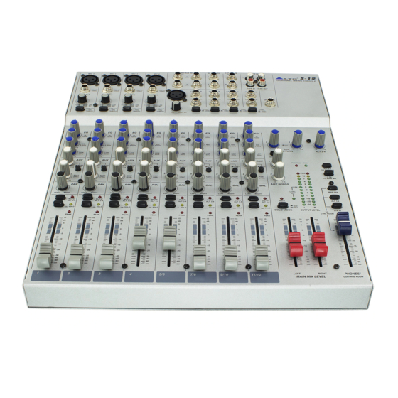
12-channel mixing console
Hide thumbs
Also See for S-12:
- Service manual (41 pages) ,
- Operating instructions and repair parts list (22 pages) ,
- Operating instructions manual (22 pages)
Table of Contents
Advertisement
Quick Links
Download this manual
See also:
Service Manual
Advertisement
Table of Contents

Related Manuals for Alto S-12


Summary of Contents for Alto S-12
- Page 1 User's Manual S-12 12-CHANNEL MIXING CONSOLE www.altoproaudio.com Version 2.0 January 2003 English...
- Page 2 the recommended fuse type as indicated in this manual. SAFETY RELATED SYMBOLS Do not short-circuit the fuse holder. Before replacing the fuse, make sure that the product is OFF and disconnected CAUTION from the AC outlet. RISK OF ELECTRIC SHOCK DO NOT OPEN Protective Ground This symbol, wherever used, alerts you to the pre-...
- Page 3 LTO S-12 is an extremely flexible, ultra-low noise 12-channel console, configured with 4 mono and 4 stereo input channels, each channel is equipped with a variety of key features including a warm, natural sounding EQ, Peak LEDs MUTE/ALT3-4, SOLO-in-place and high quality fader.
-
Page 4: Table Of Contents
TABLE OF CONTENTS 1.INTRODUCTION................................4 2.FEATURES................................5 3.GETTING STARTED..............................6 4.CONTROL ELEMENTS.............................7 The mono MIC/LINE channels..........................8 INPUT LEVEL setting............................8 LOW CUT FILTER............................8 STEREO INPUTS.............................9 +4dBu / -10dBV..............................9 PHONES................................9 The 3 BANDS EQUALISER..........................9 AUX SEND ..............................10 PAN..................................10 4.10 MUTE / ALT 3-4 .............................10 4.11 SOLO ................................10 4.12 SOLO LED ..............................10 4.13 PEAK................................10 4.14 FADER................................10... -
Page 5: Introduction
1.INTRODUCTION Your S-12 is a 12-channel mixer and it is one of the most popular compact mixing consoles in the world. In fact it has been sold already in terms of thousands of units worldwide. Despite its compact dimensions, great performances and sound quality are insured thanks to the specification of the components used and the building quality. -
Page 6: Features
2. FEATURES The S-12 12-Channel Mixing Console is designed for the professional application, and presents with the following specific features: -. Ultra-low noise 12-channel 2+2-bus mixing console -. 4 MIC input channels with gold plated XLRs and balanced Line inputs -. -
Page 7: Getting Started
3.3 Before turning on the S-12 you shall connect it to a power amplifier and turn-on the mixer BEFORE the power amp- lifier. Once you have finished your working session you shall turn the mixer off AFTER the power amplifier. -
Page 8: Control Elements
4. CONTROL ELEMENTS CTRL ROOM STEREO AUX RETURN AUX SEND 2-TRACK IN/OUT OUTPUT MIC 1 MIC 2 MIC 3 MIC 4 LEFT(MONO) RIGHT 12-CHANNEL MIXING CONSOLE LEFT RIGHT TAPE IN TAPE OUT BAL OR BAL OR BAL OR BAL OR LINE IN 5/6 LINE IN 7/8 LINE IN 9/10... -
Page 9: The Mono Mic/Line Channels
4.1 The mono MIC/LINE channels These are Channel 1 through Channel 4. You can connect balanced, low im- pedance microphones to the XLR socket. On the 1/4" phone jack you can connect either a microphone or a line level instrument. You shall never connect MIC 1 an unbalanced microphone to the XLR socket if you do not want to damage both the Microphone and the Mixer. -
Page 10: Stereo Inputs
4.4 STEREO INPUTS These are Channel 5 through 12. They are LINE IN 5/6 LINE IN 7/8 LINE IN 9/10 LINE IN 11/12 organised in stereo pair and they are provided with 1/4" TRS phone sockets. LEFT (MONO) LEFT (MONO) LEFT (MONO) LEFT(MONO) PHONES... -
Page 11: Aux Send
4.13 PEAK Inside your S-12 the audio signal is monitored in several different stages and then sent to the PEAK Led. When this Led blinks, it warns you that you are reaching signal saturation and possible distortion. The PEAK Led will blink with a level that is 6dB before actual clipping. -
Page 12: Insert
4.15 INSERT Insert points are provided for the Mono Mic Channels. CHANNEL INSERT When you insert a jack in the insert socket, the signal -FADER/PRE-EQ TIP SEND/RING RETURN) will be taken out after the Input Gain Control (Trim), sent to an external processor such a compressor- limiter, and returned into the channel strip immediately before the EQ section. - Page 13 -. AUX SEND The both switches are used to determine the master AUX SEND levels. The adjustable range is from - to +15dB. When the effect unit connected to mixer has no input gain control, you can get a further +15dB gain available from these AUX SEND outputs.
- Page 14 -. POWER This LED indicates when the Power is on in your S-12. -. PHANTOM This LED indicates when the Phantom Power is switched on.
-
Page 15: Rear Panel
4.17 REAR PANEL -. AC INLET & FUSE HOLDER Use it to connect your S-12 to the Main AC with the supplied AC cord. Please check the Voltage available in your Country and how the Voltage for your S-12 is configured before attempting to... -
Page 16: Installation & Connection
5. INSTALLATION & CONNECTION Ok, you have got to this point you are now in the position to successfully operate your S-12. However, we advise you to read carefully the following section to be the real Master of your own Mix. Not paying attention enough to the Input signal level, to the routing of the signal and the assignment of the signal will result in unwanted distortion, a corrupted signal or no sound at all. - Page 17 B. Wiring Configuration You can connect unbalanced equipment to balanced inputs and outputs. Simply follow these schematics. Ring=Right Signal Sleeve Ring Strain Clamp Tip=Left Signal Sleeve=Ground/Screen Use for Headphone, Stereo Return 1/4" Stereo (TRS) Jack Plug Sleeve Tip=Signal Strain Clamp Sleeve=Ground/Screen Use for Mono Line In, Mono 1/4"Jack Plugs 1/4"...
- Page 18 Ring=Return Signal (Connected together) To Channel Insert Sleeve=Ground/Screen Tip=Signal To Tape or FX Input Sleeve=Ground/Screen 'Tapped' Connection Direct Output Lead (Enables the Insert to be used as a Direct Output while maintaining the channel signal flow) To Processor Input Sleeve=Ground/Screen Tip=Send Signal To Channel Insert Ring=Return Signal...
-
Page 19: For The Experts Who Want To Know More
6. FOR THE EXPERTS WHO WANT TO KNOW MORE As we have told you previously in this Manual, the Aux Send 2 Control both on Mono and stereo channels is factory wired as POST-FADER. If you have some skill in electronic components soldering you can modify this setting and have all your AUX sends configured as PRE-FADER. -
Page 20: System Block Diagrams
7. SYSTEM BLOCK DIAGRAMS LOGIC SEND SEND SOLO(PFL) SOLO(PFL) AFL-R AFL-L AUX-2 AUX-2 AUX-1 AUX-1 ALT-4(R) ALT-4(R) ALT-3(L) ALT-3(L) RIGHT-BUS RIGHT-BUS LEFT-BUS LEFT-BUS... -
Page 21: Technical Specifications
8. TECHNICAL SPECIFICATIONS Mono input channels Microphone input electronically balanced, discrete input configuration Frequency response 10Hz to 55kHz, +/-3dB Distortion (THD&N) 0.005% at +4dBu, 1kHz Gain range 0dB to 60dB(MIC), SNR (Signal Noise Rated) 115dB Line input electronically balanced Frequency response 10Hz to 55kHz, +/-3dB Distortion (THD&N) 0.005% at +4dBu, 1kHz... -
Page 22: Warranty
9. WARRANTY 1. WARRANTY REGISTRATION CARD To obtain Warranty Service, the buyer should first fill out and return the enclosed Warranty Registration Card within 10 days of the Purchase Date. All the information presented in this Warranty Registration Card gives the manufacturer a better understanding of the sales status, so as to purport a more effective and efficient after-sales warranty service. - Page 23 Tel: 886-4-22313737 email: info@altomobile.com Fax: 886-4-22346757 All rights reserved to ALTO Mobile. Due to continued development in response to customer feedback, product features, specifications and/or internal/external design may be changed without prior notice. No photocopying, translation or reproduction of any part of this user manual is allowed without prior written permission.Copyright...
Need help?
Do you have a question about the S-12 and is the answer not in the manual?
Questions and answers