
Subscribe to Our Youtube Channel
Related Manuals for Alto AMX-140FX USB


Summary of Contents for Alto AMX-140FX USB
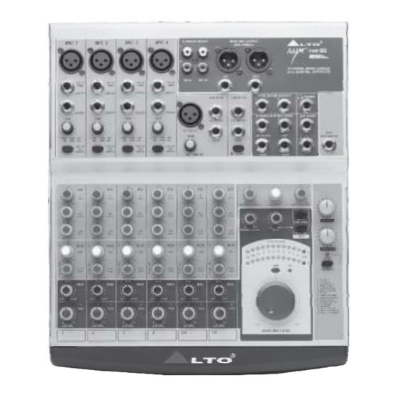
- Page 1 User's Manual AMX-140FX USB 14-CHANNEL MIXING CONSOLE/ with DIGITAL EFFECTS www.altoproaudio.com Version 1.0 February 2006 English...
- Page 2 SAFETY RELATED SYMBOLS Fuse To prevent fire and damage to the product, use only the recommended fuse type as indicated in this CAUTION manual. Do not short-circuit the fuse holder. Before RISK OF ELECTRIC SHOCK DO NOT OPEN replacing the fuse, make sure that the product is OFF and disconnected from the AC outlet.
- Page 3 LTO AMX-140FX USB mixing console is equipped with 4 mono input channels (these are provided with ultra low noise microphone pre-amplifiers and phantom power at +48 Volt), 2 stereo input channels, 2 stereo aux returns and 2TK IN.
-
Page 4: Table Of Contents
TABLE OF CONTENTS 1.INTRODUCTION..............................4 2.FEATURES................................5 3.READY TO START?...............................6 4.CONTROL ELEMENTS............................7 MONO MIC/LINE Channels .........................8 INPUT LEVEL Setting ..........................8 MONO Channel INSERT ..........................8 LOW CUT Switch ............................8 STEREO Inputs ............................9 3 BANDS EQUALIZER Controls ........................9 AUX SENDS Controls ..........................9 PAN/BAL Control ............................10 PEAK LED ..............................10 4.10 LEVEL Control ............................10 4.11 MAIN MIX LEVEL Dial ..........................10... -
Page 5: Introduction
PA installations. The AMX-140FX USB mixing console is packed with some key features that can not be found in other consoles of its size: 4 mono (these are provided with ultra low noise microphone pre-amplifiers and phantom power at +48 Volt) and 2 stereo input channels, and each of them is provided with a 3 bands graphic equalizer for HI, MID and LOW controls ;... -
Page 6: Features
2. FEATURES The AMX-140FX USB mixing console is designed for professional application. It will provide the following features: The common features: 5 MIC input channels with gold plated XLRs and balanced LINE input 2 stereo input channels with balanced TRS jacks... -
Page 7: Ready To Start
3.3 Before turning on the AMX-140FX USB you shall connect it to a power amplifier and turn-on the mixer BEFORE the power amplifier. Once you have finished your working session you shall turn the mixer off AFTER the power amplifier. -
Page 8: Control Elements
4. CONTROL ELEMENTS CAUTION RISK OF ELECTRIC SHOCK DO NOT OPEN WARNING: SHOCK HAZARD - DO NOT OPEN AVIS: RISQUE DE CHOC ELECTRIQUE - NE PAS OUVRIR MAIN MAIN 18VAC~ MIX. MIX. RECORD PLAYBACK POWER PHANTOM RATED POWER CONSUMPTION: 27W... -
Page 9: Mono Mic/Line Channels
4.1 MONO MIC/LINE Channels MIC 1 These are channel 1 through channel 4. You can connect balanced, low impe- dance microphones to the XLR socket. On the 1/4" phone jack you can connect either a microphone or a line level instrument. You shall never connect an un- J.T. -
Page 10: Stereo Inputs
4.5 STEREO Inputs LINE IN 5/6 LINE IN 7/8 These are Channel 5 through 8. They are organised in stereo pair and provided with 1/4" TRS sockets. J.T. J.T. If you connect only the left jack, the input will operate LEFT(MONO) LEFT(MONO) in mono mode. -
Page 11: Pan/Bal Control
4.9 PEAK LED Inside your AMX-140FX USB the audio signal is monitored in several different stages and then sent to the PEAK LED. When this LED blinks, it warns you that you are reaching signal saturation and possible distortion. The PEAK LED will blink with a level that is 6dB before actual clipping. -
Page 12: 2Tk In Control
DFX TO AUX1 knob to control the input level. In AMX-140FX USB model, AUX RETURN2 (DFX) is connected rightly with the output of the internal digital effects, but, this signal flow will be broken, if you have any external signal inserted from these two jacks. -
Page 13: Bit Digital Effects
4.23 24 BIT DIGITAL EFFECTS - PRESETS Control Adjust this knob to select the right effect you wish to perform. There are total 16 options for you: several kinds of reverb, mono and stereo delay, effects with modulation, and versatile two-effect combination. -
Page 14: Main Mix Output Connectors
4.25 MAIN MIX OUTPUT Connectors MAIN MIX OUTPUT (BAL/UNBAL) The stereo output is supplied both with XLR and 1/4" TRS sockets, which is used to send the audio signal to an amplifier. Through the main mix level control, you can adjust the output level from - to +15dB. -
Page 15: Installation And Connection
Connect phantom powered microphones before switching on the +48Volt phantom power switch. If you have a power amplifier connected to your AMX-140FX USB set the level of the amplifier at no more than 75%. Now, set the CONTROL ROOM/PHONES level at no more than 50%. In this way you will be able to hear later what you are doing connecting a pair of headphones or a pair of powered studio monitor speakers. - Page 16 5.1 Audio Connection Both XLR and 1/4 " TRS connectors are available on the unit. In this way you can interface the unit in several different ways without experiencing any noise or signal loss. You can use the unit with single instruments using The mixer's main insert or on "in-line"...
- Page 17 - Insert Points Connection If you are connecting to a mixing console's main inserts, you may have a single TRS jack for Send and Return, in this case, use an insert "Y" cable that configured like the examples below. Insert Leads 1/4"...
-
Page 18: For The Experts Who Want To Know More
6. FOR THE EXPERTS WHO WANT TO KNOW MORE As we have told you previously in this manual, the AUX SEND2 control both on mono and on stereo channels is factory wired as POST-FADER. If you have some skill in electronic components soldering you can modify this setting and have all your AUX SENDS configured as PRE-FADER. -
Page 19: Preset List
7. PRESET LIST Controllable parameter Description Preset Parameter Variable range Decay time 0.8~1.1s VOCAL 1 Simulate a room with small delay time. Pre-delay 0~79ms VOCAL 2 Simulate a small space with slight decay time. Decay time 0.8~2.5s Pre-delay 0~79ms LARGE HALL Simulate a large acoustic space of the sound. -
Page 21: Technical Specification
9. TECHNICAL SPECIFICATION Mono input channels Microphone input electronically balanced, discrete input configuration Frequency response 10Hz to 55kHz, + Distortion (THD & N) 0.005% at 4dBu, 1kHz Gain range 0dB to 44dB (MIC) SNR (Signal to Noise Ratio) 115dB Line input electronically balanced Frequency response 10Hz to 55kHz,... - Page 22 Power supply (AC/AC Adaptor) Main voltage USA/Canada 100 120V~, 60Hz Europe 210 240V~, 50Hz U.K./Australia 240V~, 50Hz Power Consumption 27watts Physical Dimension (W D H) 270mm 310mm 43mm (10.63" 12.20" 1.69") Net weight 2.5Kg (6.61lb)
-
Page 23: Warranty
10. WARRANTY 1. WARRANTY REGISTRATION CARD To obtain Warranty Service, the buyer should first fill out and return the enclosed Warranty Registration Card within 10 days of the Purchase Date. All the information presented in this Warranty Registration Card gives the manufacturer a better understanding of the sales status, so as to purport a more effective and efficient after-sales warranty service. - Page 24 No. 1, Lane 17, Sec. 2, Han Shi West Road, Taichung 40151, Taiwan http://www.altoproaudio.com Tel: 886-4-22313737 email: alto@altoproaudio.com Fax: 886-4-22346757 All rights reserved to ALTO. All features and content might be changed without prior notice. Any photocopy, translation, or reproduction of part of this manual without written permission is forbidden. Copyright 2006 SEIKAKU GROUP NF02624-V1.0...
Need help?
Do you have a question about the AMX-140FX USB and is the answer not in the manual?
Questions and answers