Advertisement
Optical DVI+USB
Extender
User's Manual
for the M5-1001
Manual Contents
__________________________________________
Manual Contents
Pictorials
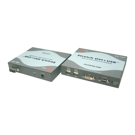
Figure 1 - Overall Optical DVI+USB Extender system
Figure 2 - Connection of DVI, USB, and RS232 cables
between Uplink box and a computer
Figure 3 - Connection of DVI, USB, and RS232 cables
between Downlink box and display
and devices
Figure 4 - Connection of duplex SC fiber cables
Figure 5 - Connection of AC/DC power adaptor
1- 0 Manual Contents
1-0
1-1
1-2
1-3
1-5
1-6
1-7
1-8
1-1
1-3
1-3
1-4
1-4
Advertisement
Table of Contents

Related Manuals for opticis M5-1001


Summary of Contents for opticis M5-1001
- Page 1 Figure 3 – Connection of DVI, USB, and RS232 cables between Downlink box and display and devices Figure 4 – Connection of duplex SC fiber cables Figure 5 – Connection of AC/DC power adaptor User’s Manual for the M5-1001 1- 0 Manual Contents...
-
Page 2: Product Description
4 port USB hubs. AC/DC Power Adapter Technical Advisory The power of M5-1001 is designed to supply to each module of Tx and Rx by plugging to each of the power plugs. Figure 1 – Overall Optical DVI+USB Extender system... - Page 3 Installation Step 4 Remove the module dust covers and connect a duplex SC fiber cable to SC Important: Please use the installation procedure below. Improper, or no receptacles of the Transmitter and Receiver boxes, as shown in Fig. 4. operation may result if the start-up sequence is not correctly followed. Carefully ensure the duplex connectors are fully engaged.
-
Page 4: Troubleshooting
60Hz refresh rate in ultimate operation. Distances up to booted. 10km (32,800feet) using Virtual DDC-EEPROM. Reset the M5-1001 using Reset button on Uplink and Downlink • Ensure your graphic card is set at not higher than SXGA •... -
Page 5: Warranty Information
This equipment has been tested and found to one (1) year from the date of purchase from Opticis or its authorized resellers. comply with the limits for a Class B digital device, pursuant to part 15 and 2 of FCC Rules, EN 55022/55024/61000-3 for CE certification. - Page 6 Canada N7M 1P7 462-120, South Korea Tel: +82 (31) 737-8033 Tel: (519) 355-0819 Fax: +82 (31) 737-8079 Fax: (519) 355-0520 For order support, please contact your Distributor or Reseller. For technical support, check with the Opticis web site www.opticis.com contact techsupp@opticis.com...
Need help?
Do you have a question about the M5-1001 and is the answer not in the manual?
Questions and answers