Table of Contents
Advertisement
Quick Links
Download this manual
See also:
Configuration Manual
Advertisement
Table of Contents

Subscribe to Our Youtube Channel
Related Manuals for B&B Electronics SPECTRE


Summary of Contents for B&B Electronics SPECTRE
-
Page 1: User Manual
SPECTRE Router USER MANUAL SPECTRE_User_Manual_2912m www.bb-elec.com www.bb-europe.com... - Page 2 B&B Electronics, Inc. SPECTRE User Manual International Headquarters B&B Electronics Mfg. Co. Inc. 707 Dayton Road Ottawa, IL 61350 USA Phone (815) 433-5100 -- General Fax (815) 433-5105 Website: www.bb-elec.com European Headquarters B&B Electronics Ltd. Westlink Commercial Park Oranmore, Co. Galway, Ireland...
- Page 3 The properties and settings associated with the cellular network connection are not available in non- cellular SPECTRE RT routers. PPPoE configuration is only available on SPECTRE RT routers. It is used to set the PPPoE connection over Ethernet. Declared quality system ISO 9001 B&B Electronics...
-
Page 4: Table Of Contents
B&B Electronics, Inc. SPECTRE User Manual Contents Safety Instructions Compliance Product disposal instructions Router Description Description Examples of possible applications: Package Contents Model Numbers Dimensions Mounting Recommendations User Interfaces Connectors Status Indicators 4.2.1 Auxiliary Port Status Indicators 4.2.1.1 Ethernet Ports 4.2.1.2 RS-232 Ports... - Page 5 Fig. 3: Recommended clearance around antennas ................. 12 Fig. 4: Cable routing ..........................13 Fig. 5: Space in front connectors ...................... 14 Fig. 6: Front panel SPECTRE 3G ....................... 15 Fig. 7: Power connector ........................18 Fig. 8: Connection of power supply connector ................18 Fig.
- Page 6 B&B Electronics, Inc. SPECTRE User Manual Table list Table 1: Auxiliary port possibilities ....................10 Table 2: Model numbers ........................10 Table 3: Front panel description ......................15 Table 4: Router status indication ....................... 16 Table 5: Ethernet LED status indication ................... 17 Table 6: RS-232 LED status indication ....................
-
Page 7: Safety Instructions
B&B Electronics, Inc. SPECTRE User Manual 1. Safety Instructions Compliance Please observe the following instructions: The router must be used in compliance with all applicable international and national laws and in compliance with any special restrictions regulating the use of the router in prescribed applications and environments. -
Page 8: Router Description
2. Router Description Description The SPECTRE industrial router series is used to connect Ethernet equipment and devices to the Internet or intranet. The SPECTRE 3G cellular router adds wireless connectivity. Thanks to the high data transfer speed of up to 14.4 Mbit/s (download) and 5.7 Mbit/s (upload),... -
Page 9: Package Contents
B&B Electronics, Inc. SPECTRE User Manual Package Contents The basic router package includes: Router Power supply (3G models only) Crossover Ethernet cable External antenna (3G models only) DIN rail adapter Installation CD Quick Start Guide Fig. 1: Contents of package SPECTRE_User_Manual_2912m www.bb-elec.com... -
Page 10: Model Numbers
B&B Electronics, Inc. SPECTRE User Manual Model Numbers Standard Features on Spectre Routers: 10/100 Ethernet, USB Host Port, Binary I/O Port, Dual SIM Card slots Auxiliary Port Functions (Model Dependent): The router can be connected as follows. PORT 1 RS232, RS485/422, ETHERNET, CNT, XC-SW (in combination with PORT 2) -
Page 11: Dimensions
B&B Electronics, Inc. SPECTRE User Manual Dimensions Fig. 2: Basic dimensions, metal box SPECTRE_User_Manual_2912m www.bb-elec.com www.bb-europe.com... -
Page 12: Mounting Recommendations
B&B Electronics, Inc. SPECTRE User Manual 3. Mounting Recommendations For best performance, please consider the following: The router should be mounted on a flat solid work surface. The DIN rail adapter is included for DIN rail mounting. Whip antennas should be kept at least 6 cm from cables and metal surfaces on all sides. -
Page 13: Fig. 4: Cable Routing
B&B Electronics, Inc. SPECTRE User Manual The cables should be bundled together and kept as far away from the antennas as possible. 1. Length: The combination of power supply and data cables can be a maximum of 1.5 meters. 2. If the length of the data cables exceeds 1.5 meters, overvoltage protectors (surge suppressors) should be used. -
Page 14: Fig. 5: Space In Front Connectors
B&B Electronics, Inc. SPECTRE User Manual Fig. 5: Space in front connectors The router must be securely grounded to earth ground for proper operation. SPECTRE_User_Manual_2912m www.bb-elec.com www.bb-europe.com... -
Page 15: User Interfaces
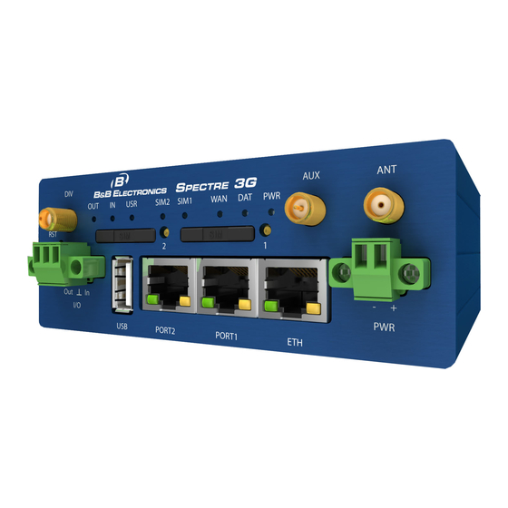
DIV* Diversity antenna USB-A Host USB connector. 3-pin Binary input and output. SIM1* SIM card holder 1 SIM2* SIM card holder 2 * 3G models only Table 3: Front panel description Fig. 6: Front panel SPECTRE 3G SPECTRE_User_Manual_2912m www.bb-elec.com www.bb-europe.com... -
Page 16: Status Indicators
B&B Electronics, Inc. SPECTRE User Manual Status Indicators Label Color State Description Blinking Router is ready Green Router is initializing. WAN* Blinking Communication in progress Flashing PPP connection established 1 x flash per Signal strength is from –50 dBm to –69 dBm... -
Page 17: Auxiliary Port Status Indicators
B&B Electronics, Inc. SPECTRE User Manual 4.2.1 Auxiliary Port Status Indicators 4.2.1.1 Ethernet Ports LED port indicator Green LED On ...... selected 100 Mbit/s Off ...... selected 10 Mbit/s Yellow LED On......the network cable is connected Blinking ………..data transmission Off ....... -
Page 18: Power Connector
B&B Electronics, Inc. SPECTRE User Manual Power Connector 2-PIN PANEL SOCKET Signal Description number mark VCC (+) Positive input of DC supply voltage (+10 to +30 VDC) GND (-) Negative input of DC supply voltage Table 9: Connection of power connector Fig. -
Page 19: Antenna Connector
B&B Electronics, Inc. SPECTRE User Manual Antenna Connector The antenna is connected to the router using the SMA connector on the front panel. The router cannot operate without the main antenna. (The port is labeled as ANT.) The ANT connector is used to connect the main antenna router. To connect the second antenna for diversity, use the connector labeled DIV. -
Page 20: Sim Card Reader
B&B Electronics, Inc. SPECTRE User Manual SIM Card Reader The SIM card reader supports 3 V and 1.8 V SIM cards. It is located on the front panel of the router. The router will not operate on UMTS networks unless an activated SIM card with an unblocked PIN is in the reader. -
Page 21: Ethernet Port
B&B Electronics, Inc. SPECTRE User Manual Ethernet Port PANEL SOCKET RJ45 Signal mark Description Data flow direction number Transmit Data – positive pole TXD+ Input/Output Transmit Data – negative pole TXD- Input/Output Receive Data – positive pole RXD+ Input/Output Receive Data – negative pole... -
Page 22: Auxiliary Port Connectors
B&B Electronics, Inc. SPECTRE User Manual The Ethernet router connection: Fig. 15: Example of router connection Auxiliary Port Connectors Port 1 Port One may configured for Ethernet, serial communications (RS-232/485/422), or (I/O – CNT) based on the router model number. Port Two may be configured for serial communications (RS-232/485/422), or (I/O –... -
Page 23: Fig. 16: Rs232 Port Connector
B&B Electronics, Inc. SPECTRE User Manual Fig. 16: RS232 port connector Signal mark Description Direction Request To Send Input Clear To Send Output Data Terminal Ready Input Data Set Ready Output Signal ground Receive Data Output Carrier Detect Output Transmit Data... -
Page 24: Rs-485/422 Ports
B&B Electronics, Inc. SPECTRE User Manual Example of a PC connection to the router: Fig. 18: PC connection to router Cable KD2 is connected to serial port PC (example COM1) Example of the RS232 equipment connection to router (possibility to use all RS232 ports): Fig. -
Page 25: Fig. 20: Jumper Position For External Supply
B&B Electronics, Inc. SPECTRE User Manual Jumper J3 Jumper J3 Jumper J2 Jumper J2 Fig. 20: Jumper Position for external supply Fig. 22: Jumper Position for internal supply Jumpery J4 and J5 Jumper J6 Fig. 23: Jumper Position for RS-422 Fig. -
Page 26: Fig. 24: Rs485/422 Connector
B&B Electronics, Inc. SPECTRE User Manual Connector Pinout Fig. 24: RS485/422 connector RS-485 Mode Signal mark Description Data flow direction number Signal and supply ground Signal and supply ground TxRx- RS485 B (-) Input/Output TxRx+ RS485 A (+) Input/Output TxRx-... -
Page 27: Fig. 26: Connection To The Router With Data Cable Length More Than 10 M
B&B Electronics, Inc. SPECTRE User Manual Fig. 26: Connection to the router with data cable length more than 10 m With a RS-485 data cable more than 10m, it is necessary to use overvoltage protection on the router side! RS-422 Mode... -
Page 28: Fig. 27: Connection To The Router With Data Cable Length Less Than 10 M
B&B Electronics, Inc. SPECTRE User Manual Fig. 27: Connection to the router with data cable length less than 10 m Fig. 28: Connection to the router with data cable length more than 10 m With a RS422 data cable more than 10m long, it is necessary to use overvoltage protection... -
Page 29: I/O Port
B&B Electronics, Inc. SPECTRE User Manual 4.7.3 I/O Port The I/O port user interface (CNT) is used to monitor analog and binary input signals and to control binary output signals. The interface has 6 inputs and 1 output. Two of the inputs can be configured as binary counter inputs or general purpose binary inputs. -
Page 30: Selecting The Binary Input Current
B&B Electronics, Inc. SPECTRE User Manual 4.7.3.5 Selecting the Binary Input Current The input threshold for detecting a logic 1 can be set at either 8uA or 20mA using a jumper on the module board. When jumper J4 is shorted, the threshold current level is 20 mA. -
Page 31: Input/Output Connector
B&B Electronics, Inc. SPECTRE User Manual 4.7.3.6 Input/Output Connector Panel socket RJ45. Pin number Signal mark Description Data flow direction Binary input/counter input Input BIN1/CNT1 Binary input/counter input Input BIN2/CNT2 Binary input Input BIN3 Binary input Input BIN4 Signal ground... -
Page 32: Fig. 29: Connection Of The I/O Port Circuitry
B&B Electronics, Inc. SPECTRE User Manual Typical connection of the I/O port circuits: Fig. 29: Connection of the I/O Port circuitry The I/O Port registers are read and written using MODBUS ASCII slave protocol over serial port 1. Using this protocol, it is possible to configure the I/O board, read the input status, and control the output. - Page 33 B&B Electronics, Inc. SPECTRE User Manual bit 8 – Binary output OUT1 bit 9 – Automatic feeder control bit 10 – Full duplex counter CNT1/CNT2 0x0004 Maximum log entries in buffer 0x0005 Marker of log launching and alarms work 0x0006...
- Page 34 B&B Electronics, Inc. SPECTRE User Manual bit 5 – analog input upper limit overrun AN1 bit 6 – analog input lower limit overrun AN2 bit 7 – analog input upper limit overrun AN2 bit 8 – limit frequency overrun CNT1 bit 9 –...
- Page 35 B&B Electronics, Inc. SPECTRE User Manual 1. log – lower 16 bits of counter CNT2 value 0x100F 1. log – prompt frequency CNT2 0x1010 1. log – average frequency CNT2 0x1011 1. log – minimal frequency CNT2 0x1012 1. log – maximal frequency CNT2...
- Page 36 B&B Electronics, Inc. SPECTRE User Manual AN1 – upper limit (with sign) 0xF305 0xF306 bits 7-3: AN1 – metering circuit switch time 0 → 1/64 sec 1 → 2/64 sec 30 → 31/64 sec bits 2-0: AN1 – samples number for average 0 →...
-
Page 37: Table 15: Modbus Input/Output Address Space
B&B Electronics, Inc. SPECTRE User Manual CNT2 – multiplicative constant 0xF600 CNT2 – upper limit 0xF601 CNT2 – time of limit overrun [sec] 0xF602 CNT2 – time for metering reset [sec] 0xF603 0xFFFF Switch main supply off on set time [min]... -
Page 38: Usb Port
B&B Electronics, Inc. SPECTRE User Manual USB Port PANEL SOCKET USB-A Signal mark Description Data flow direction number Positive pole of 5V DC supply voltage USB data - USB data signal – negative pole Input/Output USB data + USB data signal – positive pole... -
Page 39: Fig. 31: Connecting A Plc To The Router
B&B Electronics, Inc. SPECTRE User Manual Example of connecting devices with a serial interface to the USB router: Fig. 31: Connecting a PLC to the router Connecting a USB flash drive to the USB router: Fig. 32: Connecting USB memory stick to the router SPECTRE_User_Manual_2912m www.bb-elec.com... -
Page 40: Fig. 33: I/O Connection
B&B Electronics, Inc. SPECTRE User Manual I/O Port 3-PIN PANEL SOCKET Pin no. Signal mark Description Data flow direction BIN0 Binary input Input Signal ground OUT0 Binary output Output Table 17: I/O port Connection Fig. 33: I/O connection The user interface I/O is for the processing of binary input signals and for control (settings) of binary output signals. -
Page 41: Fig. 35: Connection Of Binary Input And Output Of Router
B&B Electronics, Inc. SPECTRE User Manual Circuit example of a binary input or output connected to the router: Fig. 35: Connection of binary input and output of router SPECTRE_User_Manual_2912m www.bb-elec.com www.bb-europe.com... -
Page 42: Resetting Or Rebooting The Router
B&B Electronics, Inc. SPECTRE User Manual 5. Resetting or Rebooting the Router It is important to distinguish between resetting and rebooting the router. Action Router behavior Actions Reboot Turn off and then turn on router Disconnect and connect the power. -
Page 43: Initial Setup
B&B Electronics, Inc. SPECTRE User Manual 6. Initial Setup Before you can set up the router you will need to make all of the necessary connections. The router cannot operate without a connected antenna, SIM card (for UMTS networks), and a power supply. -
Page 44: Starting The Router
B&B Electronics, Inc. SPECTRE User Manual Starting the Router Connect power to the router. In the default setting the router will start to login automatically to the preset APN. The Ethernet port DHCP server will assign device addresses. The behavior of the router can be modified by means of the Web or Telnet interface, as described in the configuration manual. -
Page 45: Technical Parameters
Transmit: GPRS* to 3.5 W (GPRS transmission) Transmit: UMTS to 5.5 W (UMTS/HSDPA transmission) /HSDPA/EVDO* Dimensions 42x76x113 mm (DIN 35mm) SPECTRE 3G – 280 g Weight Antenna connector* SMA– 50 Ohm User interface Ethernet (10/100 Mbit/s) USB 2.0 type A host... -
Page 46: Table 21: Processor Specifications
B&B Electronics, Inc. SPECTRE User Manual 32b ARM microprocessor Memory 512 Mb DDR SDRAM 128 Mb FLASH 1 Mb MRAM Interface Serial interface RS232 Ethernet interface 10/100Mbit/s USB 2.0 interface Table 21: Processor Specifications Port IO Input/Output Binary input reed contact with trigger level 1.3 up... -
Page 47: Troubleshooting
B&B Electronics, Inc. SPECTRE User Manual 7. Troubleshooting Q. I have NAT enabled. My equipment is not connecting to the network The device's gateway has to be configured as the router. Q. The router resets itself and the Ethernet connection fails. - Page 48 B&B Electronics, Inc. SPECTRE User Manual Q. I switched the router to offline mode by SMS message, but the router is in online mode after restart. SMS messages do not permanently change the router configuration. They remain in effect only until the router is restarted.
-
Page 49: Customer Support
B&B Electronics, Inc. SPECTRE User Manual 8. Customer Support Up to date information product information is on the product website: http://www.bb-elec.com/ Maintenance: Handle the SIM card carefully. Do not bend, scratch or expose the card to static electricity. Do not clean the router with harsh chemicals, solvents or abrasive cleaners.
Need help?
Do you have a question about the SPECTRE and is the answer not in the manual?
Questions and answers