Table of Contents
Advertisement
Quick Links
History
Company was established on 15th of April 1998.
Main residence is based in Vilnius.
company started with production of
telecommunication devices.
In 2001 company expanded its fields of activity
by starting design and manufacturing of
electronical systems for wireless data transfer.
In 2002 contract of partnership and
collaboration was signed with company Pro-
Sign GmbH (Germany), considering design and
representation of graphic programming interface
iCon-L in Eastern Europe.
In 2003 Teltonika and NOKIA became partners
and started integration of NOKIA M2M
technology using NOKIA N12 module. It was
the beginning of wireless technology
development process.
In 2004, NOKIA invited Teltonika to join
presentation of M2M technology innovations in
CeBIT 2004. It was very high evaluation of a
small Lithuanian company and its possibilities,
which helped to feel peculiarities of international
business.
In 2004 Teltonika produced more than 10 new
products and solutions using EDGE
technology. It was a condition that made
Teltonika a leader of M2M integration solutions
using EDGE not only in Lithuania, but also in
Europe.
2005 was the year of two successful
international exhibitions: CEBIT 2005 and
HANNOVER MESSE 2005. These
shows opened new possibilities for offering our
products and solutions for all world.
In the year 2005 Teltonika became an
international company. We became Lithuanian -
Finnish Company. A few employees from
NOKIA joined Teltonika's staff. Presently they
successfully develop activity of new companies:
Teltonika International GmbH (Düsseldorf)
and Teltonika International Oy (Helsinki).
VoiceUSB/G10
User manual v1.0
Our vision
Our vision is to provide added value for
people and companies by
creating electronical devices and solutions,
which are based on the latest achievements
of science and technology.
We aim to help people to integrate the
latest technologies in real life, what would
bring more cosiness, comfort, freedom of
mobility and security to their everyday life.
We seek to make all our solutions an
inconceivable part of people lives.
Advertisement
Table of Contents

Related Manuals for Teltonika G10


Summary of Contents for Teltonika G10
- Page 1 Main residence is based in Vilnius. people and companies by creating electronical devices and solutions, company started with production of In 2004 Teltonika produced more than 10 new which are based on the latest achievements telecommunication devices. products and solutions using EDGE of science and technology.
- Page 2 All rights reserved. Reproduction, transfer, distribution or storage of part or all of the contents in this document in any form without the prior written permission of UAB “Teltonika“is prohibited. Other products and company name mentioned herein may be trademarks or trade names of their respective owners...
-
Page 3: Table Of Contents
VoiceUSB /G10 User Manual Table of Contents ATTENTION................................4 GENERAL SAFETY REQUIREMENTS......................4 ABOUT THE DOCUMENT ........................7 INTRODUCTION............................7 PACKAGE CONTENTS ..........................8 TECHNICAL CHARACTERISTCS......................8 Data Transfer ............................8 Mechanical characteristics ........................8 Operating characteristics ........................9 Indication ...............................10 VoiceUSB PREPARATION TO WORK ....................11 Connection of antenna.........................11 Inserting SIM card ..........................11... -
Page 4: Attention
VoiceUSB /G10 User Manual ATTENTION Do not rip the device. Do not touch the device if the device block is broken or its connecting wires are without isolation. All wireless devices for data transferring may be susceptible to interference, which could affect performance. - Page 5 VoiceUSB /G10 User Manual VoiceUSB device requires 9V 1.12 A constant power supply source that satisfies all safety requirements listed in EN 60950-1 standard. The PC and power supply source, to which the device VoiceUSB is connected, should satisfy LST EN 60950 standard. The device VoiceUSB can be used on first (Personal Computer) or second (Notebook) computer safety class.
- Page 6 VoiceUSB /G10 User Manual Wall Outlet Grouding Electrical PHASE Switch NULL Board Automatic Shutdown Device Personal Computer Picture 1.Connection scheme of VoiceUSB device VoiceUSB device can be directly connected to phone line. Disconnect device from power supply before connecting it to the phone line.
-
Page 7: About The Document
VoiceUSB /G10 User Manual ABOUT THE DOCUMENT In this document VoiceUSB device technical characteristics are presented, also it is described how to connect VoiceUSB device to other devices and how to configure it.. VoiceUSB device is being continuously improved: working quality, adding specific requirements from the clients. -
Page 8: Package Contents
VoiceUSB /G10 User Manual PACKAGE CONTENTS VoiceUSB device is delivered to the client in cardboard box with all required supplements necessary for work. Package consists of: Cardboard box. VoiceUSB device. USB A USB mini B connection cable. AC/DC power supply adapter. -
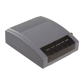
Page 9: Operating Characteristics
VoiceUSB /G10 User Manual Picture 4.2.1. External view and measurements of the device Operating characteristics The device is powered from a 9 V (DC) power supply. The PC to which the VoiceUSB device is connected must have a USB interface corresponding to USB 1.1 or USB 2.0 standards. Electrical parameters of the device are shown in Table 4.3.1. -
Page 10: Indication
VoiceUSB /G10 User Manual Indication VoiceUSB has 5 LEDs for device status indication. They are located at the top part of the device. The indication statuses of the device are described in Table 4.4.1. Table 4.4.1. Device status description Status... -
Page 11: Voiceusb Preparation To Work
VoiceUSB /G10 User Manual VoiceUSB PREPARATION TO WORK Before starting working with VoiceUSB device, antenna must be connected (see chapter 5.1). Then, insert SIM card and make sure that it is inserted properly. Connection of antenna Antenna mounting place is chosen according to mounting place features. It is recommended to mount the antenna inside the building. -
Page 12: Devices Connection To Voiceusb
VoiceUSB /G10 User Manual VoiceUSB Devices connection to Depending on what action the VoiceUSB device must perform, the following connections are to be made: Phone Computer. Picture 5.3.1 Devices connection to VoiceUSB VoiceUSB can operate in two modes: Trunk and Extension. - Page 13 VoiceUSB /G10 User Manual 5.3.1.1 Connecting phone to VoiceUSB (Trunk mode) Module also generates the voltages necessary for the call. The phone connected to the VoiceUSB device can make and receive incoming calls from the GSM network. The connection to the device is shown in picture 5.3.2.
- Page 14 VoiceUSB /G10 User Manual Picture 5.3.3. Phone call from phone to mobile phone using Trunk mode Trunk Phone call from mobile phone to phone using the mode Dial the number of the SIM card inserted in the VoiceUSB and wait for the signal.
- Page 15 VoiceUSB /G10 User Manual Step 2 Step 1 Picture 5.3.5 PBX connection to the VoiceUSB 5.3.1.2.1 Phone call examples In order to make a phone call, connect PBX to VoiceUSB (picture 5.3.5), insert the SIM card and plug the power supply.
- Page 16 VoiceUSB /G10 User Manual External Line Prefix Picture 5.3.6. Phone call from internal line number to a mobile phone using the Trunk mode Trunk Phone call from mobile phone to an internal line number using the mode Let’s say you want to make a phone call from the GSM network to an internal line number (picture 5.3.7).
- Page 17 VoiceUSB /G10 User Manual External Line Prefix Picture 5.3.7. Phone call from mobile phone to an internal line number using the Trunk mode 5.3.1.3 Trunk mode parameters All parameters can be changed with Service menu or VoiceUSB Configuration Tool. Caller ID The device supports the incoming call ID display function.
-
Page 18: Extension Mode
VoiceUSB /G10 User Manual Prefix blocking This mode allows to create a blacklist of number prefixes so the user would not be able to make a call to the number which starts with them. If user dialls a forbidden prefix, VoiceUSB will restart itself. - Page 19 VoiceUSB /G10 User Manual 5.3.2.1.1 Calling examples In order to make a phone call, connect VoiceUSB to one of the PBX Extensions sockets (picture 5.3.8), insert the SIM card and plug the power supply. Note: Calling mode may not work in the following situations: a) when VoiceUSB device is connected to the Internet;...
- Page 20 VoiceUSB /G10 User Manual Picture 5.3.9. Phone call from internal line number to a mobile phone using the Extension mode Extension Phone call from a mobile phone to internal line number using the mode Let’s say you want to make a phone call from the GSM network to the internal line number (picture 5.3.10).
- Page 21 VoiceUSB /G10 User Manual Picture 5.3.10. Phone call from a mobile phone to internal line number using the Extension mode 5.3.2.1.2 Call Through Extension mode allows you to use Call Through function, which makes calling from mobile to internal number much easier.
- Page 22 VoiceUSB /G10 User Manual Each mobile phone has it’s own way to make a pause. Please see below: For a Nokia phone: Step 1. Dial phone number of a SIM card inserted into VoiceUSB device Step 2. Press * 3 times to show ‘p’. (This causes dialing to pause) Step 3.
-
Page 23: Connecting Voiceusb To The Pc
VoiceUSB /G10 User Manual Allowed Numbers This mode allows to create a list of numbers that will be allowed to use Trunk mode. If caller‘s number will not match any number from the list, VoicUSB, will reject the call. VoiceUSB device in Extension mode was tested on PANASONIC KX – TEM284 and AGFEO AC 12 USB PBX stations. -
Page 24: Connection Of The Power Supply
VoiceUSB /G10 User Manual Connection of the power supply VoiceUSB module uses 9V 1.12 A direct current power supply source which goes with the package. The connection of the power supply is shown in picture 5.5.1 . AC/DC 9V Picture 5.5.1. Connection of the power supply... -
Page 25: Manual Pin Code Entering
VoiceUSB /G10 User Manual 5.7.1 Manual PIN code entering If SIM card PIN code request is activated, Error LED starts blinking after VoiceUSB is turned on and phone gives busy signal. This means, that the module is waiting for the PIN code which must be entered with the help of the phone buttons. -
Page 26: Voiceusb Service Menu
VoiceUSB /G10 User Manual VoiceUSB Service menu VoiceUSB device parameters can be changed using ordinary telephone connected to VoiceUSB device through a standard RJ11 connector named PHONE (see chapter 5.3.1.1. ). When the device is turned on, wait until it sets for work. If required enter PIN code of the SIM card. After a long beep, enter Service menu password. -
Page 27: General Parameters
VoiceUSB /G10 User Manual General Parameters 6.1.1 Device operating mode control VoiceUSB device operating mode can be changed with the help of telephone. This Service menu function is activated by presing 1# on telephone. ##1111# ... 0# 1# activates Extension mode. -
Page 28: Number Dial Interval
VoiceUSB /G10 User Manual VoiceUSB device supports two USB connection modes. In Data mode device switches to data transfer mode (transfer speed – 115200bps). In FAX mode device switches to PC fax mode (data transfer speed – 19200bps). VoiceUSB device USB connection mode can be change with telephone. This Service menu function is activated by dialing 3#. -
Page 29: Pin Code Entering Control
VoiceUSB /G10 User Manual ##1111# 5# < ... # Enter new 4 digit user password and press #. ##1111# 5# < New 4 digit menu password > New Service menu password will be stored in the memory of the device. After saving the password, the device returns to the main menu. -
Page 30: Trunk Mode Parameters
VoiceUSB /G10 User Manual Trunk mode parameters 6.3.1 Caller ID type display VoiceUSB device has Caller ID recognition function. This function displays incoming caller ID. To use this function, telephone must have a display for ID showing. In Service menu dial 7# to get to Caller ID type display menu. -
Page 31: Polarity Reverse
VoiceUSB /G10 User Manual ##1111# 8# 3# <Prefix># Example. Activate prefix function by entering ##1111#8#1#0# combination. Then enter a prefix, in this case 370 and dial ##1111#8#3#370#0# combination. Now each time you dial number 123456 in VoiceUSB device, in telephone number will be dialled with prefix 370 123456. -
Page 32: Extension Mode Parameters
VoiceUSB /G10 User Manual Extension mode parameters 6.4.1 DTMF sensitivity in Extension mode Dial 11# in main menu to get to DTMF sensitivity in Extension mode menu. Dialled digits in Extension mode signal level can be changed in DTMF sensitivity in Extension mode menu. -
Page 33: Number Blocking In Trunk Mode
VoiceUSB /G10 User Manual This command activates entry supplement function. When the function is activated, place in the list has to be chosen. This is done by dialing the list place number from 0 to 9 and pressing #. In such matter the particular list place is chosen for the blocked prefix. -
Page 34: Allowed Numbers In Extension Mode
VoiceUSB /G10 User Manual 6.5.2.1 Add entry Dial 3# in Number blocking menu to add new entry. ##1111# 13# … 0# This command activates number adding function When the function is activated, choose an entry number in the list. This is done by dialing the list place number from 0 to 9 and pressing #. The specified place in the list for the blocked number will be selected. -
Page 35: Restoring Default Settings
VoiceUSB /G10 User Manual Dial 2# to disable allowed numbers‘ list function. ##1111# 14# When the mode is activated, the phone calls can be made only from the numbers in the formed list. Other numbers will be ignored. 6.5.3.1 Add entry Dial 3# to add new entry to allowed numbers‘... -
Page 36: Default Settings
VoiceUSB /G10 User Manual ##1111# 6.6.1 Default settings Default parameters Device operating mode Trunk Country Lithuania* USB connection mode Data Number dial interval Service menu password 1111 PIN code entering Manual PIN code Caller ID display Number prefix Polarity reverse... -
Page 37: Table Of Parameters
VoiceUSB /G10 User Manual Table of Parameters ##1111# 1# 1# 0# Activate Extension mode ##1111# 1# 2# 0# Activate Trunk mode ##1111# 2# <Country code># Coutry selection ##1111# 3# 1# 0# USB connection in Data mode ##1111# 3# 2# 0# USB connection in FAX mode ##1111# 4# (2...6) # 0#... -
Page 38: Acronyms
VoiceUSB device drivers and software from www.teltonika.com, download the newest VoiceUSB device firmware and update it from www.teltonika.com. If all direction above were performed but the problem still remains please contact our technical support team via e-mail support@teltonika.lt. We will be glad to help You. -
Page 39: List Of Countries
VoiceUSB /G10 User Manual List of Countries Default Denmark2 106. Madagascar2 157. Senegal Albania Dominica 107. Malawi 158. Seychelles Andorra Dominican Republic 108. Malaysia1 159. Sierra Leone1 Angola Ecuador 109. Malaysia2 160. Sierra Leone2 Anguilla El Salvador 110. Mali 161. Singapore...
Need help?
Do you have a question about the G10 and is the answer not in the manual?
Questions and answers