
Related Manuals for Liebert GXT2-10000RT208


Summary of Contents for Liebert GXT2-10000RT208
- Page 1 DISCONTINUED PRODUCT AC Power For Business-Critical Continuity™ Liebert GXT2-10000RT208 ® ™ User Manual–10kVA, 60 Hz, 120/208/240V...
- Page 2 DISCONTINUED PRODUCT...
-
Page 3: Table Of Contents
ROGRAM Liebert GXT2-10000RT208 Configuration Program Features ..... . . 20 What You Will Need ............20... - Page 4 Options Tab..............25 Options Tab Used With Earlier Liebert GXT2 Models ......26 Battery Tab .
- Page 5 11.1.1 DB-9 Interface Port ............32 11.1.2 Communications—Liebert SNMP/OCWEBCARD SNMP Adapter ..... 33 11.2...
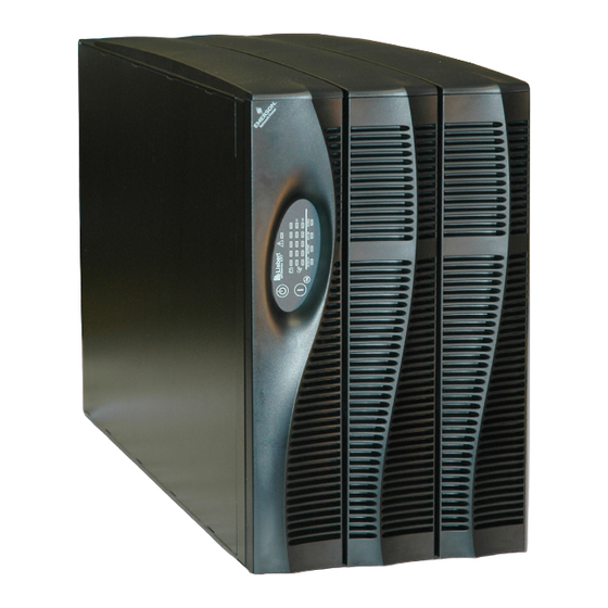
- Page 6 FIGURES Figure 1 10 kVA Dual Inverter Liebert GXT2-10000RT208, front and rear views ....7 Figure 2 Internal battery pack and connector ..........7 Figure 3 Hardwire terminal blocks .
-
Page 7: Important Safety Instructions
Do not continue to use the UPS if the front panel indications are not in accordance with these operating instructions or if the UPS performance alters in use. Refer all faults to your local dealer, Liebert representative or the Liebert Worldwide Support Group. - Page 8 When replacing batteries, replace with the same Liebert authorized replacement battery kits. When replacing the power module, replace it with the same Liebert authorized replacement power module kit. CAUTION Do not dispose of battery or batteries in a fire. The battery may explode.
-
Page 9: Glossary Of Symbols
Glossary of Symbols LOSSARY OF YMBOLS Risk of electrical shock Indicates caution followed by important instructions AC input AC output Requests the user to consult the manual Indicates the unit contains a valve-regulated lead acid battery PbH2SO4 Recycle DC voltage Equipment grounding conductor Bonded to ground AC voltage... -
Page 10: Introduction And System Description
Sensitive electronic equipment operates best from sinewave power. For ease of use, the Liebert GXT2-10000RT208 features a light-emitting diode (LED) display to indi- cate both load percentage and battery capacity. It also provides self-diagnostic tests, a combination ON/Alarm Silence/Battery Test button, a Standby button, user configurable program and two levels of alarms when the unit is operating on battery. -
Page 11: System Description
Battery Charger The battery charger utilizes energy from the utility power and precisely regulates it to continuously float charge the batteries. The batteries are being charged whenever the Liebert GXT2-10000RT208 is plugged in, even when the UPS is not turned on. -
Page 12: Dc To Dc Converter
(20°C to 25°C). Optional external battery cabinets are available to extend battery run times. Static Bypass The Liebert GXT2-10000RT208 provides an alternate path for utility power to the connected load in the unlikely event of a UPS malfunction. Should the UPS have an overload, overtemperature or UPS failure condition, the UPS automatically transfers the connected load to bypass. -
Page 13: Major Components
Major Components AJOR OMPONENTS The Liebert GXT2-10000RT208 is composed of three major assemblies to provide easier handling, installation and versatility. Main Frame and Electronics This 6U cabinet arrives without internal batteries to lighten the UPS for easier installation. Once the cabinet has been placed in its final floor or rack position, the internal batteries may be installed. -
Page 14: Input/Output Terminal Blocks And Optional Output Distribution
Major Components Input/Output Terminal Blocks and Optional Output Distribution The UPS is shipped with hardwire terminal blocks. For maximum flexibility, additional distribution options are available that provide the benefit of output receptacle convenience. Figure 3 Hardwire terminal blocks INPUT OUTPUT Figure 4 Optional output distribution modules PD-101... -
Page 15: What
• Battery cover grille • Power Module cover grille • Battery pack brackets - 2 • Liebert MultiLink software CD • Liebert MultiLink serial cable, 10 ft. (3m) • Rack mount handles • Support bases - 2 • Mounting hardware •... -
Page 16: Installation And Configuration
UPS operation in sustained temperatures above 77°F (25°C) reduces battery life. Install the Main Cabinet The Liebert GXT2-10000RT208 may be installed either as a tower unit or in a rack, depending on available space and use considerations. Determine the type of installation and follow the appropriate instructions in either 6.1.1 - Tower UPS Installation or 6.1.2 - Installing the Adjustable Rack-... -
Page 17: Installing The Adjustable Rack-Mount Kit-Sold Separately
This kit contains parts needed to mount several different models of UPS and external battery cabi- nets into EIA310-D standard four-post racks that are 18-32" deep (457-813mm). The weight limit per pair of adjustable rack-mounting brackets is 200 pounds (91 kg). Liebert rack-mount bracket kit, part # RMKIT18-32, includes: Item Quantity... - Page 18 Installation and Configuration 4. Get eight (8) M4 screws and eight (8) M4 nuts from the M4 nuts screws hardware pack in this kit. Each nut has a locking, nylon insert that begins gripping the screw when it is halfway tight.
-
Page 19: External Battery Cabinet Installation
Installation and Configuration External Battery Cabinet Installation Optional Liebert external battery cabinets may be connected to the UPS to provide additional battery run time. External battery cabinets are designed to be placed on one side of the UPS or stacked beneath the UPS. -
Page 20: Connect Input/Output Power
Installation and Configuration Connect Input/Output Power The UPS has hardwire terminal blocks for input and output electrical connections. Optional output distribution modules permit connecting additional loads to the UPS. These optional plug-and-play distribution modules offer different types and numbers of connection plugs. WARNING The UPS must be completely powered down before beginning to make these electrical connections. -
Page 21: Input & Output Terminal Block Connections
Installation and Configuration 6.3.2 Input & Output Terminal Block Connections Conduit entry holes are provided on the rear and side of the box. Input and output wiring should not share the same conduit. Table 1 Electrical requirements Recommended Wire Maximum Wire Terminal Input Current Recommended (Max.) External... -
Page 22: Add An Output Power Distribution Module-Optional
6.3.3 Add an Output Power Distribution Module—Optional To add an optional output distribution module to the Liebert GXT2 10000RT208: 1. Remove the four screws securing the blank output distribution cover plate to the rear of the UPS. The cover is at top left corner in the tower configuration and at the bottom left in the rack configuration. -
Page 23: Install The Internal Battery Packs
Installation and Configuration Install the Internal Battery Packs To facilitate shipping and installation, the Liebert GXT2-10000RT208 ships without the internal bat- tery packs installed. Once the UPS is installed in place, the internal battery packs must be installed. Controls and... -
Page 24: Initial Startup And Electrical Checks
Initial Startup and Electrical Checks NITIAL TARTUP AND LECTRICAL HECKS Initial Startup and the Configuration Program—The UPS ships with a default 120 VAC L-N setting. This is also the most robust setting in that it can operate with either input phase angle (120 or 180 degrees). -
Page 25: Output Receptacle Distribution Options
Initial Startup and Electrical Checks 18. Press the On button for one second. The bypass indicator will light for several seconds before the UPS On indicator turns on continuously. If the batteries are charged above 90% of capacity, automatic battery test will run for about 15 seconds. 19. -
Page 26: Configuration Program
• Select the number of external battery cabinets connected to the UPS to adjust the remaining run- time calculations reported by the UPS Liebert software products • Modify the shutdown setting of DB-9 pin 6 (for information on pin assignments, see 11.0 - Com-... -
Page 27: Configuration Program-Installation
NOTE If an accessory communication card has been installed in the Liebert IntelliSlot port in the UPS, the option card must be removed while using the configuration program. Use the serial communication cable to connect COM1 or COM2 of the host computer to the DB-9 com- munication port on the rear of the UPS. -
Page 28: Configuration Program-Operation
COM port. Liebert MultiLink typically restarts automatically whenever the computer restarts. • The Liebert IntelliSlot port in the UPS CANNOT be in use by an internal, optional communica- tion card in the UPS card slot. Remove the option card. -
Page 29: On-Screen Reminders
Configuration Program 8.5.4 On-Screen Reminders As pending changes are selected, on-screen messages will remind the user if the UPS may be On, or must be Off, for the setting to be pro- grammed once the Apply or OK button is pressed. -
Page 30: Ups Tab
L-N voltages available. Select the voltage that matches the nominal utility in your location. Output Voltage Selection Notes For the Liebert GXT2 dual inverter models, this sets the L1-N and the L2-N nominal voltage. The L1-L2 voltage depends upon the phase angle of the input utility and is auto-detected when power is first applied. -
Page 31: Frequency Selection
Configuration Program 8.6.3 Frequency Selection The UPS is normally designed for 50Hz or 60Hz operation. The factory default corresponds to the model. All models are capable of being used as 50Hz or 60Hz systems. The UPS will Auto-sense the utility frequency when first plugged in and set the nominal frequency to match. Therefore, for all nor- mal use the Auto Sense button should be selected. -
Page 32: Options Tab Used With Earlier Liebert Gxt2 Models
This version of the configuration program will accompany Liebert GXT2 UPS models that support new programming features accessible using the Options Tab. If Version 1.6 (or later) is used with an earlier Liebert GXT2 model (with an earlier UPS firmware version), the Any Mode Shutdown features cannot be changed. -
Page 33: Battery Tab
The Liebert GXT2-10000RT208 automatically detects external battery cabinets when they are connected. Use the Battery Cabinets Number selection box to select non-Liebert battery cabinets when used with the UPS. 8.9.1 Low Battery Time Warning The UPS will estimate remaining operating time when on batteries. A low battery alarm is activated if the estimated time reaches the Low Battery Time. -
Page 34: About Tab
Configuration Program 8.10 About Tab Version number may be confirmed using the About Tab. DISCONTINUED PRODUCT... -
Page 35: Controls And Indicators
ON - Pressing this button will start up the UPS in order to provide conditioned and protected power. Alarm Silence - To silence alarms, press this button for at least one Second. After the alarm is silenced, the Liebert GXT2-10000RT208 will reactivate the alarm system to alert of additional problems. NOTE The LOW BATTERY and BYPASS reminder alarms CANNOT be silenced. -
Page 36: L1 & L2 Load Level Indicators (Two Rows Of Indicators: 4 Green, 1 Amber)
Should the battery fail this test, the red Fault indicator along with the A and C diagnostic indicators will illuminate and an alarm will sound (refer to 13.0 - Troubleshooting). The remote test feature functions with Liebert MultiLink 3 software and can remotely initiate the battery test. Fault Indicator (Red) The Fault indicator is illuminated if the UPS has detected a problem. -
Page 37: Modes Of Operation
Modes of Operation 10.0 M ODES OF PERATION 10.1 Normal Mode Operation During normal operation, utility power provides energy to the UPS. The filters, power factor correction circuit and the inverter process this power to provide computer grade power to connected loads. The UPS maintains the batteries in a fully charged state. -
Page 38: Communications
OMMUNICATIONS 11.1 Communications Interface Port The Liebert GXT2-10000RT208 UPS has a standard DB-9 serial port female connector located on the rear of the UPS unit. Several signals are provided on this port and are assigned as follows: Table 2 DB-9 pin assignment... -
Page 39: 11.1.2 Communications-Liebert Snmp/Ocwebcard Snmp Adapter
2. Pin 4 requires a 5-12 VDC signal to shutdown. This normally comes form the serial port using Liebert’s contact closure cable. It cannot be used with just a contact closure unless the relay is used to switch a voltage source. A 5-12 VDC signal for 1.5 seconds or greater is required to signal a shutdown. -
Page 40: Remote Emergency Power Off
Communications 11.4 Remote Emergency Power Off The UPS is equipped with a Remote Emergency Power Off (REPO) connector. The user must supply a means of interfacing with the REPO circuit to allow disconnecting the UPS input feeder breaker to remove all sources of power to the UPS and connected equipment to comply with national and local wiring codes and regulations. -
Page 41: Maintenance
Failure to recharge the batteries peri- odically will permanently degrade battery capacity. The Liebert GXT2-10000RT208 is designed to allow the user to safely replace the internal batteries. Read the safety cautions before proceeding. Contact your local dealer or Liebert representative to obtain the appropriate replacement battery kit part number and pricing. -
Page 42: Ups Power Module Replacement
Maintenance 12.2 UPS Power Module Replacement CAUTION The UPS must be switched to manual bypass before personnel begin to replace the power module. NOTE During the procedure, the connected load will not be protected from power disturbances, such as spikes, sags and failure. To remove the UPS power module without shutting off power to the connected load: 1. -
Page 43: Figure 10 Ups Back Panel-Control Location
Maintenance Figure 10 UPS back panel—control location Output Input Bypass Inverter Output Breaker 60A 250V~/T Input Breaker 60A 250V~/T Figure 11 Power module replacement Power module pulled out of UPS (Retaining grilles removed for clarity) DISCONTINUED PRODUCT... -
Page 44: Troubleshooting
Troubleshooting 13.0 T ROUBLESHOOTING The information below indicates various symptoms a user may encounter in the event the Liebert GXT2-10000RT208 develops a problem. Use this information to determine whether external factors caused the problem and how to remedy the situation. -
Page 45: Table 4 Alarm Conditions
5 minutes while the battery charger is not operational. If a problem persists, consult your local dealer, Liebert representative or contact the Liebert World- wide Support Group. Please have the UPS model number and serial number available at the time of your inquiry. -
Page 46: Troubleshooting Guide
Wait 30 minutes to allow UPS to cool, then restart UPS. illuminated. condition. Load is on bypass If UPS does not restart, contact your local dealer, Liebert power. representative or the Liebert Worldwide Support Group. Fault and Bypass indicators UPS internal DC bus UPS requires service. - Page 47 Liebert representative or the Liebert Worldwide Support Group. Fault indicator and diagnostic UPS requires service. Contact your local dealer, Liebert indicators D and E are UPS charger fault. Representative or the Liebert Worldwide Support Group.
-
Page 48: Table 6 Battery Run Times
Troubleshooting Using the configuration program, the user may specify the number of GXT2-288VBATT external bat- tery cabinets attached to the UPS. The factory default is programmed for internal batteries only. Table 6 shows estimated run times at different loads. Table 6 Battery run times Battery/External 10000VA Run Time... -
Page 49: Auto-Learning Battery Run Times
13.1 Auto-Learning Battery Run Times As batteries age, the estimated run times may become less accurate. The Liebert GXT2-10000RT208 is programmed to “learn” from a full battery discharge and modify the estimated run time for the measured battery capacity. This can improve accuracy and compensate for aging batteries or batter- ies that operate at different ambient temperatures. -
Page 50: Specifications
Specifications 14.0 S PECIFICATIONS Table 7 UPS specifications Model Number Liebert GXT2-10000RT208 8000W/8660VA at 127/220 (120 or 240 degrees only) 8000W/8660VA at 120/208 (120 or 240 degrees) 8000W/10000VA at 120/240 (180 degrees) Model Rating 8000W/10000VA at 115/230 (180 degrees only) -
Page 51: Table 8 Battery Specifications
Specifications Table 7 UPS specifications (continued) Model Number Liebert GXT2-10000RT208 Bypass Protection Limits Disable Bypass Operation If input voltage exceeds ±15% of the nominal voltage Re-enable Bypass Operation If input voltage returns to within ±10% of nominal output voltage Disable Bypass Operation... -
Page 52: Table 10 Optional Output Distribution Specifications-Pd-102
Specifications Table 10 Optional output distribution specifications—PD-102 Model Number PD-102 DIMENSIONS, W x D x H Shipping, in. (mm) 8.86 x 10.43 x 7.87 (225 x 265 x 200) WEIGHT lb (kg) Unit 4.6 (2.1) Shipping 6.0 (2.7) ELECTRICAL SPECIFICATIONS Amp Rating 60 Amps Input Power Connections... -
Page 53: Product Warranty Registration
• Visit the Quick Links section of our Website at: http://www.liebert.com • Click on Product Warranty Registration and fill in the form. If you have any questions, please contact us at: US: 800-222-5877 Outside the US: 614-841-6755 upstech@emersonnetworkpower.com Contact Liebert Global Services at: US: 800-LIEBERT (800-543-2378) powertech@emersonnetworkpower.com DISCONTINUED PRODUCT... - Page 54 Specifications DISCONTINUED PRODUCT...
- Page 55 DISCONTINUED PRODUCT...
- Page 56 +39 049 9719 111 While every precaution has been taken to ensure the accuracy Fax: +39 049 5841 257 and completeness of this literature, Liebert Corporation assumes no Asia responsibility and disclaims all liability for damages resulting from use of 7/F, Dah Sing Financial Centre this information or for any errors or omissions.
Need help?
Do you have a question about the GXT2-10000RT208 and is the answer not in the manual?
Questions and answers