
Related Manuals for Liebert GXT


Summary of Contents for Liebert GXT
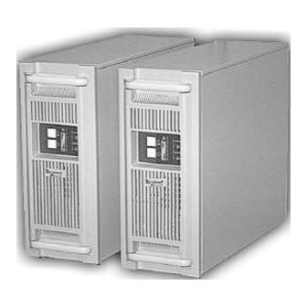
- Page 1 OWER ROTECTION UPStation GXT™ 1800-2700 VA 208V ANUAL English / Español...
-
Page 2: Important Safety Instructions
IMPORTANT SAFETY INSTRUCTIONS WARNING: Do not attempt to service this product yourself except to replace the battery. Opening or removing the cover may expose you to dangerous voltages, even when the AC cord is disconnected from the electrical outlet. Refer all servicing to qualified service personnel. SAVE THESE INSTRUCTIONS. -
Page 3: Introduction And System Description
The UPStation GXT™, 208 VAC models comes in nominal power ratings of 1800 or 2700 VA. Complete specifications appear near the end of this section. The UPStation GXT™ is a compact, “on-line” UPS. -
Page 4: Major Components
UPS, and the amount of distortion reflected on the utility is reduced. This results in cleaner power being available to other devices in the building not being protected by the UPStation GXT™. INVERTER In normal operation, the inverter utilizes the DC output of the power factor correction circuit and “inverts”... -
Page 5: General Installation
For battery run times, refer to the Typical Battery Discharge Curves. DYNAMIC BYPASS The UPStation GXT™ provides an alternate path for utility power to the connected load, in the unlikely event of a UPS malfunction. Should the UPS have an overload, over temperature, or UPS failure condition, the UPS automatically transfers the connected load to bypass. - Page 6 Support Base Rack-Tower models are stabilized by the supplied support bases. RACK-MOUNT CONVERSION DIAGRAMS Cover Screws RACK-MOUNT UPS CONVERSION AND INSTALLATION Unpack the UPS carefully noting the packing method. Retain the box and packing material for possible future shipment. CAUTION: The UPS is heavy (see specifications). Take proper precautions when lifting or moving it.
- Page 7 4 and 5. Remove display template to change the orientation of the display. You may also rotate the “Liebert UPStation GXT™” plate located at left of display area. NOTE: UPS unit MUST be supported by a shelf, brackets or slide rails on each side.
- Page 8 OPTIONAL BATTERY CABINET(S) INSTALLATION Up to two optional battery cabinets may be connected to the UPS to provide additional run time. Battery cabinets are designed to be placed on either side or beneath the UPS. Unpack the UPS battery cabinet(s) carefully noting the packing method. Retain the box and packing material for possible future shipment.
- Page 9 2- DB-9 Interface Port 3- AC Inlet 4- Intellislot TM Communications Port 5- Circuit Protector or fuse 6- Output Voltage Selector Switches 7- Battery Cable Connector UPStation GXT™ 2700 VA 1800 VA Rack Tower Rack Tower Fault Indicator Bypass Indicator UPS On Indicator...
-
Page 10: Controls And Indicators
To silence alarms, press this button for at least one half second while alarm conditions are present. After the alarm is silenced, the UPStation GXT™ will reactivate the alarm system to alert of additional problems. Note: The low battery and bypass reminder alarms cannot be silenced. -
Page 11: Operation
UPS On Indicator (Green) The UPS On indicator is illuminated when the UPS inverter is operating and supplying power to your connected loads. Battery Indicator (Amber) The Battery indicator is illuminated when the UPS is operating from the battery system. AC Input Indicator (Green) The AC Input indicator is illuminated when utility power is available and within the input specification. - Page 12 Figure 1- Normal Mode Operation at 51-75% loading BATTERY MODE OPERATION Battery mode occurs in event of an extreme input voltage condition or complete utility failure. The battery system supplies power through the DC-DC converter to the inverter to generate power for the connected load. During battery mode an alarm sounds every 10 seconds.
-
Page 13: Communications Interface Port
Monitoring of the UPS via a computer system is easily made with a Liebert SiteNet® 1 shutdown kit (sold separately). -
Page 14: Ups Intelligent Communications
24 hours every four to six months to ensure full recharge of the batteries. The UPStation GXT™ UPS is designed to allow the user to safely replace the batteries. Read the safety cautions before proceeding. Contact your dealer to obtain the appropriate replacement battery kit. -
Page 15: Battery Replacement Procedures
It is not necessary to turn off and disconnect the UPS from the utility power prior to opening the battery replacement door; however, it is your option. The UPStation GXT batteries can be replaced without turning off the UPS or your connected equipment. - Page 16 Connect the battery wire connectors together. Slide battery assembly completely into the UPS, reposition the large battery door and replace the screws removed in step 3. 10. Reposition small battery door and replace the screws removed in step 2 to lock top battery door closed.
-
Page 17: Rack/Tower Battery Replacement
RACK / TOWER BATTERY REPLACEMENT Rear View Top cover screws Two front rubber feet Large battery door Screw hidden by small battery door Large battery door Flange screws Aerial View w/top cover removed Front bezel (cover) Small battery door Battery connector... - Page 18 UPStation GXT™ BATTERY RUN TIMES (Discharge times are at 25° C ambient) 1800 VA Rack Tower 2700 VA Rack Tower...
-
Page 19: Troubleshooting
Battery Test failure TROUBLESHOOTING The information below indicates various symptoms a user may encounter in the event the UPStation GXT™ develops a problem. Use this information to determine whether external factors cause the problem and how to remedy the situation. -
Page 20: Troubleshooting Guide
TROUBLESHOOTING GUIDE PROBLEM UPS fails to start when on button is pressed Battery indicator is illuminated UPS has reduced battery time Fault and Bypass indicators and all load level LEDs are illuminated Fault and Bypass indicators and diagnostic LED A are illuminated Fault and Bypass indicators and diagnostic LED B are illuminated... -
Page 21: Specifications
MODEL NUMBER MODEL RATING VA/W DIMENSIONS: in (mm) Unit W x D x H Shipping 13.38 x 26.0 x 22.25 W x D x H WEIGHT: lbs (kg) Unit Shipping INPUT AC PARAMETERS Voltage Range (typical) 100% - 90% Loading 90% - 70% Loading 70% - 30% Loading 30% - 0% Loading... -
Page 22: Limited Warranty
(4) to six (6) months when not in use. If the UPS fails to conform with the above warranty within the two year warranty period, Liebert will repair or replace the UPS, at Liebert's option. Repairs or replacements are warranted for the remainder of the original warranty period. -
Page 23: Technical Support
Worldwide FAX tech support The Company Behind The Products With more than 500,000 installations around the globe, Liebert is the world leader in computer protection systems. Since its founding in 1965, Liebert has developed a complete range of support and protection systems for sensitive...
Need help?
Do you have a question about the GXT and is the answer not in the manual?
Questions and answers