Murphy PowerView PV1000 Operation Manual
Powerview
Hide thumbs
Also See for PowerView PV1000:
- Brochure & specs (6 pages) ,
- Hardware installation manual (18 pages)
Table of Contents
Advertisement
Quick Links
Advertisement
Table of Contents

Related Manuals for Murphy PowerView PV1000


Summary of Contents for Murphy PowerView PV1000
- Page 1 PowerView™ Model PV1000 Operations Manual 00-02-0619 01-22-08 Section 78...
- Page 2 The latest version of this manual can be found at www.fwmurphy.com. Warranty A limited warranty on materials and workmanship is given with this FW Murphy product. A copy of the warranty may be viewed or printed by going to www.fwmurphy.com/support/warranty.htm Please read the following information before installing.
-
Page 3: Table Of Contents
Mounting Options ......................2 PV1000 Navigation........................3 Fixed Buttons .......................3 Virtual Buttons......................4 Menu ..........................5 Popup...........................5 Setting Up your PV1000 Display for the First Time............. 6 Product Features........................8 Power Up ........................8 Main Menu ........................8 Gauge Display......................9 GPS Display.......................12 Engine Diagnostics ....................15 Fault Code Popups ....................17... - Page 4 (THIS PAGE INTENTIONALLY LEFT BLANK)
-
Page 5: Product Information
The PowerView™ Model PV1000 display is designed for instrumentation and control on electronically controlled engines communicating using SAE J1939 and NMEA 2000. The PV1000 display is a multifunction tool that enables equipment operators to view many different engine, transmission, and equipment parameters and service codes. -
Page 6: Mounting Options
Mounting Options Two mounting options are provided for the PV1000 display. The in-dash mounting option will require a hole to be cut for insertion of the display. A template is provided with the depth and dimensions of the display for easy installation. The gimbal-mount method enables the display to be installed on top of the dash. -
Page 7: Pv1000 Navigation
PV1000 Navigation Navigating the PV1000 display is accomplished using two sets of buttons - one fixed and one virtual - to access menus, popups, and make selections from available options. Each time a button is pressed, confirmation of the button press is indicated by the amber light at the lower left corner of the display. -
Page 8: Virtual Buttons
Virtual Buttons A column of vertical buttons located to the right of the display are virtual buttons. They will change according to the options available for the screen being displayed. Section 78 00-02-0619 01-22-08 - 4 -... -
Page 9: Menu
Menu The Menu can be accessed at any time, from any screen being displayed, by pressing the Menu button. The Menu button symbol is always located in the first position of the fixed buttons. Popup The Popup button utilizes the virtual keys to the right of the display to provide shortcuts for navigation and display options. -
Page 10: Setting Up Your Pv1000 Display For The First Time
Setting Up your PV1000 Display for the First Time The guidelines presented below are intended for setting up the PV1000 display for the first time. Once the configuration is set up, there is no need to revisit or change any of the settings. - Page 11 • (F) NMEA – Plug D NOTE: This setting needs to match the wiring configuration for how your PV1000 display was installed. Refer to the “Wiring Instructions” section of the “PowerView Model PV1000 Installation Manual” for the associated wiring diagrams for each of these options.
-
Page 12: Product Features
Product Features Power Up The PowerView display is most frequently installed with power connected to the ignition. When the ignition is turned on, the PowerView display powers up and the engine health statistics can be viewed via preset gauges. To see more gauge screens, press the Next or Previous buttons. -
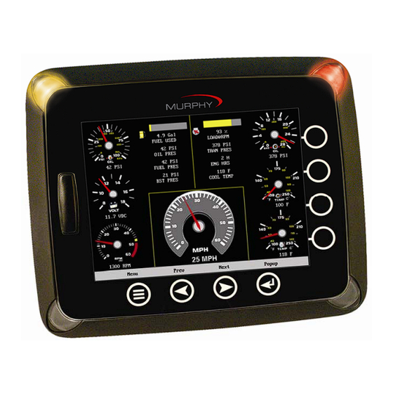
Page 13: Gauge Display
Gauge Display The Gauge Display screen consists of several predefined layouts that contain combinations of analog gauges, curved bar (half-moon) gauges, straight bar gauges, or digital (text) readouts. These screens are displayed upon startup. You can scroll through the various gauge screens by pressing the Next and Previous buttons. This can be repeated until all screens have been viewed. - Page 14 Screen Names - When selected, a small window appears at the top right of the display. This window contains the names of each of the screens that are currently “Turned ON”. Using the Previous and Next buttons allows you to scroll through and display the various gauge configurations.
- Page 15 Day/Night - Allows you to toggle the display screen between Day View and Night View. NOTE: This feature can also be changed in the “User Settings” section of this manual. Home - This one-touch navigation feature allows a pre-defined Home screen to be accessed from the available Gauge Display screens.
-
Page 16: Gps Display
NOTE: See “GPS Utilities” for information on setting GPS display options. NOTE: In order for this information to be available on the PV1000, a GPS antenna (P/N 78-70-0250) that is NMEA2000 compatible must be installed. This NMEA2000 device (along with any others) should be networked using valid NMEA2000 cabling and terminating resistors (Installation Kit P/N 78-70-0261). - Page 17 Split Mode – toggles between a split screen with up to 3 gauges, or a full grid screen without gauges, as shown below. Current Position – is used to return to the current machine/satellite position after having moved the cross-hairs to another location on the map. WPT –...
- Page 18 Tracking shows the current route and any waypoints you have set. A green arrow indicates your current position, while the red square indicates the initial point of tracking. The green dot represents a waypoint. Save Track – saves the current track line. Gauge Display –...
-
Page 19: Engine Diagnostics
Engine Diagnostics When choosing this selection, the display will query the engine(s) ECU and provide feedback on any diagnostic codes that have been activated and stored in the ECU for service needs. The Engine Diagnostics option displays faults based on engine or auxiliary source. Section 78 00-02-0619 01-22-08... - Page 20 • Description – Most common SPN's and FMI's have text for the description stored in the PV1000 display. If there is no text, then this SPN and FMI must be defined by referring to the engine manufacturer, or the SAE J1939 standard.
-
Page 21: Fault Code Popups
Fault Code Popups A fault condition will trigger a popup dialog box on the screen describing the nature of the fault. Corresponding red or amber fault lights on the corners of the unit are also activated to indicate the severity of the fault. The following screens are examples of warning and shutdown fault code popups. -
Page 22: User Settings
User Settings User Settings provides options to specify viewing preferences for the PV1000 DISPLAY. Pressing Prev and Next navigates through the options, and Up and Down scrolls through the selections for each option. Ambient Light Night and Day options are provided for ambient lighting. The screens below illustrate these options. -
Page 23: Home Screen
Brightness You can set the brightness control by using the UP and DOWN virtual buttons to change the settings in 5% increments until the desired brightness is achieved. Units Select how units are displayed by using the UP and DOWN virtual buttons to select: •... -
Page 24: Utilities
Utilities is selected. System Settings The System Settings screen displays the current software version loaded on the PV1000 DISPLAY. You can set individual settings for the available options, or choose to select “Restore Defaults” for the factory settings. - Page 25 Splash screens contain the graphics that are displayed during start-up and also to the right of the menus. There are default splash screens with the Murphy logo and user splash screens that allow you to load your own custom pictures or graphics to display.
- Page 26 Utilities menu. Press Select to display the custom graphic. Restore Default Splash If custom user graphics have been loaded and are currently being displayed, selecting this option will restore the default splash screens with the Murphy logo. Section 78 00-02-0619 01-22-08...
- Page 27 Engine Configuration This features provides a quick look at your engine configuration and current status of each source parameter. The following is a list of field definitions contained on the ENGINE CONFIGURATION screen: • Plug – identifies the connector plug (A,B,C, or D) on back of the PowerView unit. •...
- Page 28 Snapshot Display The Snapshot feature contains several screens of graphs representing current readings for various parameters such as Engine Oil Pressure, Fuel Temperature, and Fuel Delivery Pressure. Four graphs are displayed at a time. Use UP and DOWN to navigate to the other snapshot screens.
- Page 29 Use Snapshot Setup to determine which parameters are displayed on the snapshot graphs. Press UP and DOWN to highlight the desired parameter in the list and press MODIFY PARAMETER. Then press Next to move the cursor to the “Group” field and press UP or DOWN to scroll through the options.
- Page 30 Press RESTORE DEFAULTS to replace all user selected settings with factory default settings. Section 78 00-02-0619 01-22-08 - 26 -...
- Page 31 Service Reminder This feature allows the configuration of several countdown timers that indicate when to perform preventative maintenance. To set the ‘Timeout Duration’ field, press Next to highlight the desired item in the list, then press UP and DOWN to increase the timeout duration in 100 hour increments. Once set, pressing RESET TIMER starts the clock countdown and is shown in the ‘Hours Remaining’...
- Page 32 Pressing RESTORE DEFAULTS will reset all values in the ‘Timeout Duration’ and ‘Hours Remaining’ fields to zero. To complete the action press RESTORE, or CANCEL to abort. Section 78 00-02-0619 01-22-08 - 28 -...
-
Page 33: Gps Utilities
GPS Utilities When using a GPS device, GPS Utilities will allow you to configure and monitor satellite tracking data. The following sub-menu is displayed when GPS Utilities is selected. Satellite Status This feature displays a graphic indicating the satellites currently visible in orbit and the signal strength of each satellite. - Page 34 Track and Position Setup This feature allows you to define the amount of detail to display, including longitude and latitude information, on the GPS map. Position Format Selection – determines how longitude and latitude information is displayed. Chart Presentation – select US or International chart presentation. Press Prev or Next to move from field to field, then press UP and DOWN to scroll through the options.
- Page 35 Chart and Time Setup This menu option allows you to set up viewing options for the GPS Display. Chart Setup Parameters – use the Check/Uncheck button to select the information you want displayed on the GPS screen. Splitscreen Gauge Selection – allows you to custom configure the type of gauges you want to display in split screen mode.
- Page 36 Waypoint Manager Waypoints allow you to mark specific locations by latitude and longitude. Once the waypoints are established, the Waypoint Manager allows you to associate an icon with them for identification. You can delete a single waypoint by using the Delete button, or all of them at once with Delete All.
- Page 37 Track Manager The Track Manager feature allows you to show and hide tracks on the GPS map. You can selectively delete tracks or delete all tracks at once. Press UP or DOWN to select the desired track, then press SHOW/HIDE to toggle the status of the track or DELETE to delete it.
-
Page 38: Reprogramming The Pv1000 Display
Reprogramming the PV1000 Display The SD card slot on the front of the unit is used for reprogramming the unit. If you have been asked to create the card to reprogram the unit, you should: 1. Insert card into reader/writer. -
Page 39: Specifications
Specifications Electrical Display 6.4” Color transmissive TFT LCD Resolution VGA, 640 x 480 pixels Orientation Landscape Backlighting CCFL, 350 cd/m² (50,000 h lifetime) not replaceable Sharp ARM9 LH7A404, 200 MHz Processor Philips ARM7 LPC2194 70 MHz Flash Memory 16 Mbytes 32 Mbytes SDRAM EEPROM 32 Kbytes... - Page 40 Environmental Operating Temperature -20º C to +85º C (-40º C with optional heater) Storage Temperature -40º C to +85º C Protection IP68 Emissions IEC 60945, 95/54/EC Immunity SAE J1113, ISO 11452 Section 78 00-02-0619 01-22-08 - 36 -...
- Page 41 Section 78 00-02-0619 01-22-08 - 37 -...
- Page 42 Murphy Industries, Inc. This document, including textual matter and illustrations, is copyright protected by Murphy Industries, Inc., with all rights reserved. (c) 2008 Murphy Industries, Inc. Other third party product or trade names referenced herein are the property of their respective owners and are used for identification purposes only.
Need help?
Do you have a question about the PowerView PV1000 and is the answer not in the manual?
Questions and answers