
Subscribe to Our Youtube Channel
Related Manuals for Murphy PowerView PV750


Summary of Contents for Murphy PowerView PV750
- Page 1 PowerView™ Model PV750 Installation and Operations Manual 00-02-0686 08-20-10 Section 78 1-800-548-1191 - http://www.partdeal.com - info@partdeal.com...
- Page 2 The latest version of this manual can be found at www.fwmurphy.com. Please read the following information before installing. BEFORE BEGINNING INSTALLATION OF THIS MURPHY PRODUCT: Read and follow all installation instructions. Please contact FW MURPHY immediately if you have any questions. 1-800-548-1191 - http://www.partdeal.com - info@partdeal.com...
-
Page 3: Table Of Contents
Table of Contents Table of Contents ........................iii Hardware Installation ......................1 Inspecting Package Contents ..................1 Dash-Mounted Installation.................... 1 Wiring Instructions ......................... 5 Single Engine ....................... 5 PVA and Dual Engine Gages ..................6 ... - Page 4 (THIS PAGE INTENTIONALLY LEFT BLANK) 1-800-548-1191 - http://www.partdeal.com - info@partdeal.com...
-
Page 5: Hardware Installation
NOTE: When using the paper template from the manual, if you downloaded this document from the FW Murphy website, be aware that the pdf file may not automatically print to scale. When submitting the file for print, you will need to select “None”... - Page 6 Mounting the Unit 1. Place the back side of the display through the opening in the dash. 2. Use the four screws to line up the unit with the drilled holes. 3. Push the unit through the opening and screws through the drilled holes until the back of the case is flush.
-
Page 7: Wiring Instructions
Wiring Instructions The following illustrations are examples of various typical quick-connect options for setup. Wiring harnesses are sold separately. Single Engine Section 78 00-02-0686 08-20-10 - 5 - 1-800-548-1191 - http://www.partdeal.com - info@partdeal.com... -
Page 8: Pva And Dual Engine Gages
PVA and Dual Engine Gages NOTE: Port B and C connectors are keyed differently than Port A and D connectors to ensure proper connection. If both PVA gages and Video camera are going to be utilized, an extra harness is needed. -
Page 9: Usb Wiring
USB Wiring Section 78 00-02-0686 08-20-10 - 7 - 1-800-548-1191 - http://www.partdeal.com - info@partdeal.com... -
Page 10: Analog Video
Analog Video NOTE: If both PVA gages and video camera are going to be utilized, an extra harness is needed. P/N 78000688 PVW-750-MINI. Section 78 00-02-0686 08-20-10 - 8 - 1-800-548-1191 - http://www.partdeal.com - info@partdeal.com... -
Page 11: Nmea Wiring
NMEA Wiring Section 78 00-02-0686 08-20-10 - 9 - 1-800-548-1191 - http://www.partdeal.com - info@partdeal.com... -
Page 12: Pin Specifications For Deutsch Dt04-6P Style Connections
Pin Specifications for Deutsch DT04-6P Style Connections Signal Definitions CAN: 3 ports according to CAN specification 2.; 1 port isolated according to NMEA 2000 USB 2.0 host Video input (optional): NTSC/PAL Inputs (3) 0-5 VDC analog inputs, (1) input configurable to support measurement frequencies from 2 Hz - 10kHz values from 0-100% duty cycle Output: Digital, capable of sinking 500mA. -
Page 13: Wiring Schematic
Wiring Schematic Section 78 00-02-0686 08-20-10 - 11 - 1-800-548-1191 - http://www.partdeal.com - info@partdeal.com... -
Page 14: Pv750 Features And Operations
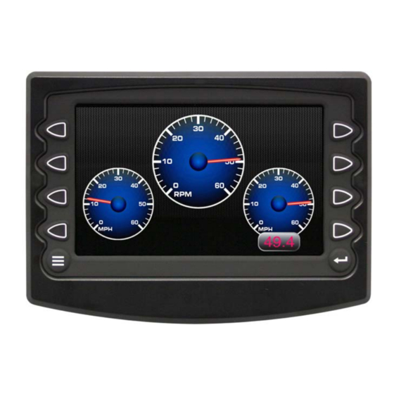
PV750 Features and Operations Flat Screen Display A color screen displays gauges, soft key commands, and fault messages, as well as menu options for setup and configuration. Soft Key Commands Columns of vertical commands may be located to the left and/or right of the display. They will change according to the options available for the screen being displayed. -
Page 15: Setting Up Your Pv750 Display For The First Time
The guidelines presented below are intended for setting up the PV750 display for the first time. Once the configuration is set up, there is no need to revisit or change any of the settings. NOTE: If you require assistance during the set up process, contact FW Murphy customer support at (918) 317-4100. - Page 16 3. From the ‘Utilities’ sub-menu, select ‘System Settings’. The following screen is displayed. 4. With the cursor highlighting the J1939 source addresses, use the left side soft keys to scroll through the ports and the right side soft keys to change the address. Press the Save key to save selected changes or the Restore Defaults key to return to the default settings.
-
Page 17: Product Features
Product Features Power Up The PowerView display is most frequently installed with power connected to the ignition. When the ignition is turned on, the PowerView display powers up and the engine health statistics can be viewed via preset gauges. To see more gauge screens, press the Enter key. Main Menu The main menu is activated at any time by pressing the Menu key on the display. -
Page 18: Gauge Display
Gauge Display The Gauge Display screen consists of several predefined layouts that contain combinations of analog gauges, straight bar gauges, or digital (text) readouts. These screens are displayed upon startup. To scroll through the various gauge screens, press the Prev and Next soft keys. This can be repeated until all screens have been viewed. - Page 19 Home - This one-touch navigation feature allows a pre-defined Home screen to be accessed from the available Gauge Display screens. Once selected, the Home screen will be displayed anytime the Home key is pressed. NOTE: For instructions on how to setup the Home screen, refer to the “User Settings”...
- Page 20 .Previous and Next keys allow you to scroll through and display the various gauge screens. NOTE: For instructions on how to turn screens ON or OFF, refer to the “User Settings” section of this manual. Section 78 00-02-0686 08-20-10 - 18 - 1-800-548-1191 - http://www.partdeal.com - info@partdeal.com...
-
Page 21: Engine Diagnostics
Engine Diagnostics Choosing Engine Diagnostics from the Menu, the display will query the engine(s) ECU and provide feedback on any diagnostic codes that have been activated and stored in the ECU for service needs. The Engine Diagnostics option displays faults based on engine or auxiliary source. Section 78 00-02-0686 08-20-10... - Page 22 The following is a list of field definitions contained on the Engine Diagnostics screen: • Source – identifies the component having the fault; engine 1, 2, or auxiliary. • Status – indicates whether the fault has been corrected. • SPN –"Suspect Parameter Number" - fault code If not translated into text by the PV750 display, see the engine manufacturer's literature for the definition of the SPN number.
-
Page 23: Fault Code Popups
Fault Code Popups A fault condition will trigger a popup dialog box on the screen describing the nature of the fault. Corresponding red or amber fault lights on the corners of the unit are also activated to indicate the severity of the fault. The following screens are examples of warning and shutdown fault code popups. -
Page 24: User Settings
User Settings User Settings provides options to specify viewing preferences for the PV750 Display. Pressing Up and Down navigates through the options. To change an option, press the corresponding soft key next to the desired soft key command. Ambient Light Night and Day options are provided for ambient lighting. - Page 25 Brightness You can set the brightness control by using the soft keys to change the settings in +1% and +5% increments until the desired brightness is achieved. NOTE: Brightness level will change with ambient light setting. Two brightness levels are saved; one for day and one for night. Units Select how units are displayed by using the soft keys to select from the following: •...
- Page 26 Language This option allows you to select the language that will be displayed on the PowerView. Available languages include English, French, Spanish, German, Italian, and Chinese. Languages are selected from the soft keys. Press More to view additional languages. Home Screen The Home Screen option allows you to specify a favorite screen from the Screen Names list that can be used as a shortcut back to that screen.
- Page 27 Screen Setup The Screen Setup option provides a list of screens that may be shown when accessing the Gauge Display screens. The ‘Status’ field will indicate which screen has been specified as the HOME screen. It also provides the user the ability to turn the screens ON or OFF by pressing the Enable/Disable soft key.
- Page 28 Restore Defaults Restore Defaults sets the display to the original factory settings. During troubleshooting, this can be used as a last resort to completely reset the display to a known state. To restore the default user settings, press Restore Defaults. The following confirmation screen is displayed.
-
Page 29: Utilities
Utilities Utilities allow you to reset external gauges and configure communication settings. It is typically only accessed when the unit is first installed in order to configure the unit. The following sub- menu is displayed when Utilities is selected. System Settings The System Settings screen displays the current software version loaded on the PV750 display. - Page 30 Service Reminders This option allows you to reset the 5 built-in service reminders: • Change Engine Oil – Default interval 50.0 Hrs. • Chang Air Filters – Default interval 75.0 Hrs. • Change Hydraulic Oil – Default interval 100.0 Hrs. •...
-
Page 31: Specifications
Specifications Electrical Display 7” / 178mm color transmissive TFT LCD Resolution WVGA, 800 x 480 pixels, 16-bit color Aspect Ratio 16:9 Orientation Landscape or portrait Backlighting LED, 400-500 cd/mC (50,000 h lifetime) Microprocessor Freescale IMX.31 32bit, 400 MHz Operating System QNX operating system Flash Memory 2 GB... - Page 32 Mechanical (W x H) 8.37 x 6.0 in (212.5 x 152.3mm) landscape Dimensions Unit Depth – 3.57 in (90.8mm) Shipping Weight Approximately 2.5 lbs. (1.13 kg) Case Material Polycarbonate back case Section 78 00-02-0686 08-20-10 - 30 - 1-800-548-1191 - http://www.partdeal.com - info@partdeal.com...
- Page 33 1-800-548-1191 - http://www.partdeal.com - info@partdeal.com...
- Page 34 1-800-548-1191 - http://www.partdeal.com - info@partdeal.com...
- Page 35 Section 78 00-02-0686 08-13-10 - 33 - 1-800-548-1191 - http://www.partdeal.com - info@partdeal.com...
- Page 36 1-800-548-1191 - http://www.partdeal.com - info@partdeal.com...
Need help?
Do you have a question about the PowerView PV750 and is the answer not in the manual?
Questions and answers