Table of Contents
Advertisement
Advertisement
Table of Contents

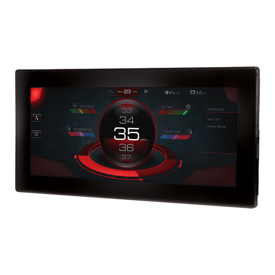
Summary of Contents for Murphy PowerView PV1200
- Page 1 PowerView ® Model PV1200 Installation Manual 00-02-1021 2018-07-16 Section 78...
- Page 2 In order to consistently bring you the highest quality, full-featured products, we reserve the right to change our specifications and designs at any time. The latest version of this manual can be found at enovationcontrols.com. Please read the following information before installing. BEFORE BEGINNING INSTALLATION OF THIS MURPHY PRODUCT: Read and follow all installation instructions.
-
Page 3: Table Of Contents
Table of Contents Hardware Installation ......................... 3 Inspecting Package Contents ..................3 Dash-Mounted Installation....................3 Preparing the Dash ....................4 Mounting the Unit ..................... 5 Available Accessories for the PV1200 ..............5 Wiring Information ........................6 Pinout Specifications ....................6 Configuration Information ......................8 Wiring Schematics –... - Page 4 THIS PAGE INTENTIONALLY LEFT BLANK...
-
Page 5: Hardware Installation
Hardware Installation The following instructions will guide you through installing the PowerView display. Inspecting Package Contents Before attempting to install the product, it is recommended that you ensure all parts are accounted for and inspect each item for damage (which sometimes occurs during shipping). The items included in the box are: •... -
Page 6: Preparing The Dash
Tools needed. • Drill with 7/32 in. size bit • Jigsaw • Screw Driver Preparing the Dash Determine the location of the PV1200 in the dash. Cut a hole in the dash to these dimensions: (For actual cutout template, see support.enovationcontrols.com, then search for PV1200) •... -
Page 7: Mounting The Unit
Mounting the Unit 1. Place the back side of the display through the opening in the dash. 2. Use the four included screws from the mounting kit (78-00-1294) to attach the unit to the bracket and torque to 10 inch-pounds. Available Accessories for the PV1200 The following PV1200 accessories are available through Enovation Controls: Part Number... -
Page 8: Wiring Information
Wiring Information Pinout Specifications Black Connector Digital Input 1 Analog Input 3 Analog Input 2 Analog Input 1 CAN1 Low CAN1 High Battery Ground Analog Input 3 Ground Analog Input 2 Ground Analog Input 1 Ground Digital Input 3 Digital Input 2 Frequency Output 1 Ignition Input AMP 770680-1... - Page 9 Gray Connector Video Input 1 Video Input 2 Video Input 3 RS-485 High RS-485 Low No Connect No Connect No Connect Video Input 1 Ground Video Input 2 Ground Video Input 3 Ground No Connect Frequency Input AMP 770680-4 Frequency Return No Connect USB D- USB D+...
-
Page 10: Configuration Information
Ethernet (M12) Connector Ethernet TX+ Ethernet RX+ Ethernet TX- Ethernet RX- M-12, 5-pos, A-coded, Ethernet Ground Plastic Knurl Connector Only NOTE: Ethernet connectivity is optional. Configuration Information Follow these steps to download a custom configuration to the PV1200 display: Step Action Turn off the display. -
Page 11: Wiring Schematics - Black Connector
Wiring Schematics – Black Connector WARNING: Failure to install the unit per the specified wiring diagrams may cause damage to the unit. DO NOT connect power to the video ground. Warranty is void for damage caused by incorrect wiring. Section 78 00-02-1021 2018-07-16 - 9 -... -
Page 12: Wiring Schematics - Gray Connector
Wiring Schematics – Gray Connector WARNING: Failure to install the unit per the specified wiring diagrams may cause damage to the unit. DO NOT connect power to the video ground. Warranty is void for damage caused by incorrect wiring. Section 78 00-02-1021 2018-07-16 - 10 -... -
Page 13: Specifications
Specifications Computing Main Processor: Renesas R-Car M2, 32-Bit Arm Cortex A15 Processor @ 1.5 GHz Operating System: Real-time Operating System ® Storage: 8GB Flash memory for Operating System, Application and Configuration Ram: 512 Mb DDR3-SDRAM Graphics: Renesas graphics processor Displays 12.3”... - Page 14 Electrical Operating Volts: 6-36 VDC, Reverse polarity protected (1) 500 mA Switched Low-side Outputs: (1) Frequency Output (2Hz – 3KHz) (3) Analog 0-5 VDC, 4-20mA, Resistive, 10-bit resolution Inputs: (5) Discrete digital, active high (1) Frequency In (2Hz – 10KHz) 5V pk-pk min, 120V pk-pk max Environmental Operating -40°C to +70°C (-40°F to +158°F)
-
Page 15: Dimensions
Dimensions Section 78 00-02-1021 2018-07-16 - 13 -... - Page 16 Section 78 00-02-1021 2018-07-16 - 14 -...


Need help?
Do you have a question about the PowerView PV1200 and is the answer not in the manual?
Questions and answers