
Related Manuals for X-TREME XB-610


Summary of Contents for X-TREME XB-610
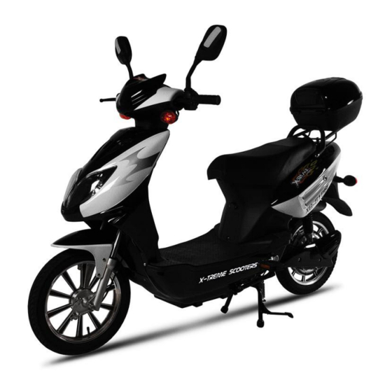
- Page 1 X-Treme Electric Moped XB-610 Electric Bicycle Owner Manual Read this manual completely before riding your electric bicycle...
-
Page 2: Table Of Contents
Contents Table of Contents………………………………………………………………………….. 2-3 Riding Safety ……………………………………………………………………………… 4-6 Product Features…………………………………………………………………………… 7 Package Contents………………………………………………….……………………….. 8 Installation Instructions…………………………………………….……………………… 8-12 Front Wheel & Brake………………………….……………………………………… 8 Handle Bar Installation………………………..……………………………………… 9 Trunk/Pedals/Mirror Installation……….…………………………………………….. 10 Battery Connection & Initial Charging Instructions………………………………… 11 Tire Inflation…………………………………………………………………………. 12 Product Specification…………….……………………………………………………….. - Page 3 How To Test Motor Sensors………………………………………………………….. 20-21 Troubleshooting…………………………………………………………………………… 21-28 Scooter Won’t Run, Charger Light Stays Green…………………………………….. 21 Scooter Won’t Run, Charger Light Stays Red & Green……………………………… 21 Is It My Throttle Or My Controller?................21-22 Throttle Voltage Test…………………………………………………………………. 22 Intermitted Power Loss………………………………………………………………. 22-23 No Power……………………………………………………………………………..
-
Page 4: Riding Safety
RIDING SAFETY Like any sport, biking carries the risk of injury and damage. By choosing to ride the electric bicycle, you assume all responsibility for these risks. Thus, you need to know and practice the rules of safe and responsible riding. YOUR INSURANCE POLICIES MAY NOT PROVIDE COVERAGE FOR ACCIDENTS INVOLVING THE USE OF THIS ELECTRIC BICYCLE. - Page 5 Never ride your electric bicycle while under the influence of alcohol or other drugs. If possible, avoid riding in bad weather, when visibility is obscured, at dusk or in the dark, or when you are very tired. Each of these conditions increases the risk of accident. Never allow children to ride.
- Page 6 night riding; follow the Rules of the Road, and take the following precautions: Make sure that your electric bicycle is equipped with correctly positioned and securely mounted reflectors. Make sure your clothing or cargo does not obstruct a reflector or light. Wear light colored, reflective clothing and accessories, any reflective device or light source that moves will help you get the attention of approaching motorists, pedestrians and other traffic.
-
Page 7: Product Features
Product features... -
Page 8: Package Contents
Package Contents: Electric Bicycle 48V 20AH Charger Left & Right Mirrors Front Tire Front Fender Left & Right Foot Pedals Ignition Keys Foot Pad Trunk User Manual Preparation for Assembly A. - Page 9 1.) INSTALLATION OF FRONT WHEEL AND BRAKE. Insert brake hub onto wheel as shown above. Slide wheel into front forks being sure to align brake hub bracket with right side fork. See image below. (When sitting on bike, front brake is on riders left side of front wheel) Slide axle thru left fork, then spacer before inserting it into the left side of front wheel.
-
Page 10: 2.) Handlebar Installation
2.) HANDLEBAR INSTALLATION Locate and remove the handlebar bolt, washer & nut as shown. For access to the nut on the back side, turn the handlebars fully to the right. Slide handlebars over post in the correct position, then insert the bolt & concave washer into the front (speedometer side) of the handlebars and secure with nut on the back (riders side). -
Page 11: Trunk/Pedals/Mirror Installation
3-5.) TRUNK/PEDALS & MIRROR INSTALLATION Attach trunk to back cargo rack using the four (4) enclosed bolts/nuts & washers. Secure to rack with the washers & nuts on the underside. Attach left & right foot pedals according to correct side by lining up pedal with bearing on pedal shaft and snap into place. -
Page 12: Battery Connection & Initial Charging Instructions
6.) BATTERY CONNECTION & INITIAL CHARGING Remove battery pack and locate plug. Plug battery wire into battery pack and reinstall battery pack under foot plate. IMPORTANT: Completely charge battery for a maximum of 8 hours before use. DO NOT CHARGE FOR MORE THAN 8 HOURS THIS DAMAGE... -
Page 13: Product Specification
Product Specifications 1. Wire diagram 2. Specifications Battery Voltage 48Volt Dc,20Ah Motor Wattage 600W Wheel Size 16 inch Top Speed 35km/h Charging Time 6-8h Distance of full charge 50km Battery charging cycles <300 times Max rider weight 300lbs Two rider Left and Right Indicators Rear View mirrors... -
Page 14: Operation
Operation Your new Electric Bicycle/scooter is a revolutionary new transport product using a sealed lead acid batteries and a super high efficiency electric hub motor designed to ASSIST in the propulsion of you and your bicycle. It is important to note the following riding guidelines to ensure you get the best possible experience from your electric bicycle. -
Page 15: Battery Charging & Safety
6. Do not attempt to change any electronic components except changing light bulbs. 7. DO not attempt to modify, open or perform maintenance on the Hub Motor. 8. Any attempt to modify electrical components will void the warranty unless specifically requested by a X-treme Scooters representative. - Page 16 Maintenance ----Schedule Service Interval Daily Monthly Every Yearly Months Inspect Tires for wear and condition and inflation Check and adjust Brake Check operation of all lighting and horn devices. Replace globes if necessary Test Battery Capacity Replace Wheel Baring Grease Full Brake Pad Change over Check condition and torque settings of wheel nuts and...
-
Page 17: How To Fix Wobbly Handle Bars
How To Fix Wobbly Handle Bars Remove the instrument panel by taking out the six (6) screws from the bottom and disconnecting the wire connectors Look at the bolt that clamps the handle bars to the steering stem: is the gold spacer seated correctly? Tighten the bolt by using two 14mm wrenches –... -
Page 18: How To Replace Rear Inner Tube
Remove entire Seat and Seat Barrel from scooter. Unscrew your old controller from the frame - Leave wires connected. Mount the New Controller in its location. Transfer One Connector at a time from the old controller to the new controller. Re-install Battery. -
Page 19: How To Adjust Drum Brakes
connection. Tug on each wire to make sure its locked into the connector. Open seat and remove the 4 bolts that attaches the seat barrel to the scooter. 2 bolts on each side of the seat latch and the other 2 are in down in bottom front of seat barrel. Lift off the seat and seat barrel as one piece. -
Page 20: How To Align Front Forks
Unplug six pin and one pin connectors from instrument panel. Follow wire from throttle housing to white connector and unplug, (should be 3-pin connector with black, red and white wires). Loosen small allen head bolt from throttle housing and slide throttle from handlebar. How To Align Front Forks Remove the dash on the backside. -
Page 21: How To Test Motor Sensors
supply to the throttle, and should be within this range ( 4.9 - 5.5) Now remove the red probe from the Red wire and put it on the Green wire and need 2 recorded readings one @ no throttle and other @ 100% throttle. Should be about .2vdc @ 0 Throttle and 4.9vdc @ 100% Throttle. -
Page 22: Troubleshooting
with +5 volts from a workbench power supply--set up a multi-meter to monitor the sensor's output on one of the 3 wires. Connect the Black Voltmeter Lead to the small black wire by inserting the probe in where the wire goes into the connector. Attach the Red Voltmeter to one of the 3 wires to be tested. -
Page 23: Throttle Voltage Test
analog resistance meter of any kind, as it could damage the chip if it's a Hall-effect chip), you can test whether it's a potentiometer or not. If it is, you should get 5K ohms across red and black, and of course, 0-5K from red or black to the third wire (usually green or yellow). -
Page 24: No Power
used on a computer which has the same type of plug that will plug into the charger port, with a wire length of 2' and cut wire and discard the rest. What we are going to do is attach the voltmeter leads to this computer wire and plug into the socket to watch actual voltage while riding and mounting the voltmeter is a spot and secure it so it doesn't move but be able to watch it while on test runs. -
Page 25: After Fully Charging, Powers Only For Short Distance Use
variable controls. The brake lever has a power cut-off switch. The throttle variably controls the speed of the scooter. The scooter On/Off switch can be defective. Without a good switch the scooter has no power, but the test of this is the power light. Does the power light come on when the switch is activated to the On position? Troubleshooting: After Fully Charging, Powers Only For Short Distance Use... -
Page 26: Scooter On, Won't Run
Troubleshooting: Scooter On, Won’t Run A) If the scooter is moving when you turn the key to the “on” position without turning the throttle you will need to replace the throttle or control box. B) If scooter takes off without turning the key to “on” – you need to replace the control box. Troubleshooting: Scooter Will Not Move Scooter not moving and Lights do not work using battery, but lights do work when you plug the charger into the side of the scooter and also plug the charger into the wall-Scooter will not move at... -
Page 27: Hub Motor Tests
should change to RED or RED/RED. If you plug the charger into the scooter and no change appears, this means that you have an open circuit which could be a fuse not installed or power plug not plugged into bottom of battery pack or a bad connection. All Chargers should change state even for a few minutes if batteries are fully charged. - Page 28 2. Place the negative lead of the meter into the sensor connector where the black wire is located. Place the positive meter lead into the sensor connector where the green wire is located. Slow rotate the tire. The meter should alternate between 5 volts and 0 volts if the sensor is good. Test the other two sensor wires the same way.
-
Page 30: Diagrams
Battery Wiring Diagram... -
Page 31: Support
DO NOT RETURN TO STORE! IF YOU NEED HELP CALL TOLL FREE OR GO ONLINE 1-253-777-0690 www.x-tremescooters.com/support/ For General Information or Parts Visit www.x-tremescooters.com Revised 9/08/11...
Need help?
Do you have a question about the XB-610 and is the answer not in the manual?
Questions and answers