
Subscribe to Our Youtube Channel
Related Manuals for X-TREME XB-502


Summary of Contents for X-TREME XB-502
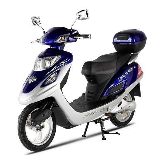
- Page 1 X-Treme Electric Moped XB-502 Electric Moped/Bicycle Owner’s Manual Read this manual completely before riding your electric bicycle...
-
Page 2: Table Of Contents
Table of Contents Table of Contents…………………………………………………………………………………. 2-3 Riding Safety……………………………………………………………………………………….. 4-6 Product Specifications……………………………………………………………………………. 7 Package Contents………………………………………………….……………………………… 8 Installation Instructions…………………………………………….……………………………… 8-12 Front Wheel & Brake………………………….…………………………………………….. 8 Handle Bar Installation………………………..…………………………………………….. 9 Headlight/Headlight Fairing Installation..…….……………………………………………. 10 Trunk/Pedals/Mirror Installation……….…………………………………………………… 11 Battery Connection & Initial Charging Instructions………………………………………. 12 Tire Inflation………………………………………………………………………………….. - Page 3 How To Test Motor Sensors……………………………………………………………….. 23-24 Troubleshooting…………………………………………………………………………………… 24-30 Scooter Won’t Run, Charger Light Stays Green…………………………………………. 24 Scooter Won’t Run, Charger Light Stays Red & Green………………………………… 24 Is It My Throttle or My Controller?................. 24-25 Throttle Voltage Test………………………………………………………………………… 25 Intermitted Power Loss…………………………………………………………………….. 25-26 No Power……………………………………………………………………………………..
-
Page 4: Riding Safety
Never carry a passenger. The maximum carrying capacity is 300 lbs. Never ride barefoot or wearing sandals. Don’t jump with your XB-502. It puts great stress on everything from frame and forks to drive train. Riders who insist on jumping their XB-502 risk serious damage to their XB-502 as well as to themselves. - Page 5 Operating Reminders and Suggestions Review all instructions carefully before riding the XB-502. Follow all rules and regulations in your area for operating a motorized bicycle. Obey the same road laws as all other road vehicles, including yielding the right-of-way to pedestrians, and stopping at red lights and stop signs.
- Page 6 90 days. Do not store your XB-502 in direct sunlight for an extended time. Store your XB-502 in a dry place. Exposing your XB-502 to rain, snow, or other precipitation may result in damage. DO NOT RETURN TO STORE! Do not use this vehicle for the first time until you have inflated the tires to the correct PSI and completely charged the battery.
-
Page 7: Product Specifications
Product features... -
Page 8: Package Contents
Remove axle from front fork & shipping crate and set aside, do not discard. There are 8 installation steps that must be done prior to using your XB-502. Be sure to do them in order and do not skip a step. 1.) INSTALLATION OF FRONT WHEEL AND BRAKE. -
Page 9: 2.) Handlebar Installation
Slide axle thru left fork, then spacer before inserting it into the left side of front wheel. Secure with nut on right side (brake side) and tighten securely 2.) HANDLEBAR INSTALLATION Locate and remove the handlebar bolt, washer & nut as shown above. Slide handlebars over post in the correct position, then insert the bolt &... -
Page 10: Headlight/Headlight Fairing Installation
3.) HEADLIGHT/HEADLIGHT FAIRING INSTALLATION Locate and remove packing material from the front headlight fairing. Attach wire clips as shown. Line up headlight fairing to front of scooter being careful not to break the plastic clips underneath. Slide the headlight fairing into place and snap. -
Page 11: Battery Connection & Initial Charging Instructions
Attach left & right foot pedals according to correct side by lining up pedal with bearing on pedal shaft and snap into place. Screw left & right mirrors into place and adjust to appropriate riding need. 7.) BATTERY CONNECTION & INITIAL CHARGING Remove battery pack and locate plug. -
Page 12: Product Specification
Product Specifications 1. Wire diagram 2. Specifications Battery Voltage 48Volt Dc,12Ah Motor Wattage 500W Wheel Size 16 inch Top Speed 20 MPH Charging Time 6-8h Distance of full charge 20 - 25 miles Battery charging cycles Around 350 times Max rider weight 300 Lbs Two rider Left and Right Indicators... -
Page 13: Operation
Operation Your new Electric Bicycle/scooter is a revolutionary new transport product using a sealed lead acid batteries and a super high efficiency electric hub motor designed to ASSIST in the propulsion of you and your bicycle. It is important to note the following riding guidelines to ensure you get the best possible experience from your electric bicycle. - Page 14 Battery Charging and & Battery Safety Charging figure 1-4 Specification: 1.Input(AC) : 100-240V frequency:50Hz/60Hz 2.Output: 54.60 ± 0.2V 3.Charge current:1.8±0.2A Charging (see figure 1-4) Ensure bike is turned off and key is removed. 1.First connect to the battery charger to the charging socket located below the front of the seat or under the front seat.
-
Page 15: Battery Charging & Safety
4) Plug the end of the charger’s cord into the socket of the adaptor first. Next connect the adaptor to the XB-502 (the charger port in located below the front of the seat). Then plug the chargers’ AC cords into the wall outlet. - Page 16 Maintenance ----Schedule Service Interval Daily Monthly Every Yearly Months Inspect Tires for wear and condition and inflation Check and adjust Brake Check operation of all lighting and horn devices. Replace globes if necessary Test Battery Capacity Replace Wheel Baring Grease Full Brake Pad Change over Check condition and torque settings of wheel nuts and...
-
Page 17: How To Guide
How To Assemble Rear Wheel 1. First, remove the two screws that hold the plastic plates on both sides of rear wheel. See figure 1-5: figure 1-5 2. Remove the screw from the end of Brake Cable, and then pull the cable out. See figure 1-6: figure 1-6 3. -
Page 18: How To Remove Front Wheel
4. Remove the two nuts on both sides of the rear wheel. See figure 1-9 figure 1-9 5. Slide the wheel forward to allow slack in the chain. 6. Now slide the chain over the rear flywheel and remove the wheel from the bicycle. How To Remove Front Wheel 1. -
Page 19: How To Install Front Wheel
How To Install Front Wheel Set your bike on a strong table or workbench to make access easier. Lift the front forks and install the front wheel. Ensure the locking washers are inserted into the holes on the forks. Insert the axle and spacer as shown above (in reverse) Install the two nuts on the end of the axle and tighten. -
Page 20: How To Replace Dash
inside and remove from scooter. Follow the wire coming out of side of motor and cut the tie straps leading up the controller. Remove the wheel nuts and remove the brake adjustment nut and remove the wheel. Let all air out of tire and use either a tire wrench or couple dull screw drivers to remove tire bead from one side of rim to remove and install the tube. -
Page 21: How To Adjust Drum Brakes
seat and seat barrel as one piece. Location of brake safety connection: You should see a box with several wires coming out of it. You will also see these wires go into quick disconnects and locate a 4 wire plug. There will only be one and on the controller side of the connector the wire colors are: Yellow, Red, Black and Green. -
Page 22: How To Test Rear Wheel & Controller
with your legs and turn the handlebars into position. Tighten the 12mm bolt and reassemble the dash. How To Test Rear Wheel & Controller Place scooter up on center kickstand, turn scooter ignition in the "ON" position. Spin rear wheel by hand and check to see if it falls in one of the following conditions: A.) Wheel spins with slight resistance –... -
Page 23: How To Test Motor Sensors
+50vdc when the ignition key switch is in the ON position. 4. DC/DC controller check. This is the smaller silver box under the headlight assembly and has 3 wires coming out of it. Red & Black wire should have 48vdc with the key on, and Yellow and Black should have 12vdc before and after the Glass Fuse. -
Page 24: Troubleshooting
unlock the lock tab one of the good pins. And pull the wire out of the controller and reconnect the connector. Tape off the gold pin so you can protect it. Return to above instructions above. Troubleshooting: Scooter Won’t Run, Charger Light Stays Green When you plug your charger into your scooter and the wall outlet the charger light stays green. -
Page 25: Throttle Voltage Test
You should also check the brake inhibit switch (there should be a wire cable coming from your brake handle), to see if it is making and breaking continuity. The brake inhibit switch turns the throttle off when you put the brakes on. It functions like a 'kill switch' should anything go wrong. You should also test the key switch in the same way. -
Page 26: No Power
2. Unplug the Large Red and Orange 2 wire connector on controller. This connection is for the Ignition switch test, on the side that has the Red and white wire by looking down inside you will see 2 silver pins and there is a little tab that you push towards the pin and the wire will come out of the connector. -
Page 27: After Fully Charging, Powers Only For Short Distance Use
Troubleshooting: After Fully Charging, Powers Only For Short Distance Use 1. Suspect the battery charger or the battery as the primary cause of short distance riding after a lengthy or full charge. If your battery charger does not have charging indicator lights then you may not be charging the battery at all if the charger is defective. -
Page 28: Scooter Will Not Move
Troubleshooting: Scooter Will Not Move Scooter not moving and Lights do not work using battery, but lights do work when you plug the charger into the side of the scooter and also plug the charger into the wall-Scooter will not move at all and all lights do not work (lights do work when you plug the charger into wall): A) No fuse in fuse assembly= add one of the fuses includes with the scooters B) Bad Fuse= unscrew the cap only on the fuse holder. -
Page 29: Hub Motor Tests
Troubleshooting: Hub Motor Tests 1. With any one of the three sensors disconnected the moped will run very jerky. It may stop but will start again if the throttle is release and then turn. If two or more sensors are disconnected the motor will not start. 3. - Page 30 Motor Winding Test: Test all motor leads from lead to lead. All readings should be .6-.7 ohms. Controller Test: Disconnect all the motor wires from the controller to run these test. Set the volt-meter to read ohms. If your meter does not auto-range set meter to 20K ohms. Check between the red and black power wires.
-
Page 31: Diagrams
Controller Connector Placement Wiring Diagram... -
Page 32: Voltmeter Wiring Diagram
Voltmeter Connection Diagram... -
Page 33: Rear Motor Diagrams
Rear Motor Diagrams... -
Page 35: Battery Wiring Diagrams
Battery Wiring Diagrams... -
Page 36: Support
DO NOT RETURN TO STORE! IF YOU NEED HELP CALL OR GO ONLINE 1-253-777-0690 www.x-tremescooters.com/support/ For General Information or Parts Visit www.x-tremescooters.com Revised 2/28/12...
Need help?
Do you have a question about the XB-502 and is the answer not in the manual?
Questions and answers