
Related Manuals for Fujitsu Siemens Computers D1858


Summary of Contents for Fujitsu Siemens Computers D1858
- Page 1 Technisches Handbuch / Technical Manual Mainboard D1858 Deutsch / English...
- Page 2 Sie haben ..technische Fragen oder Probleme? Wenden Sie sich bitte an: ● Ihren zuständigen Vertriebspartner ● Ihre Verkaufsstelle ● unsere Hotline für Kunden, die ein einzelnes Mainboard gekauft haben: +49(0) 180 3777 005 Aktuelle Informationen und Updates (z. B. BIOS-Update) zu unseren Mainboards finden Sie im Internet: http://www.fujitsu-siemens.com/mainboards Are there ...
- Page 4 Questo manuale è stato stampato su carta da riciclaggio. Denna handbok är tryckt på recyclingpapper. Dit handboek werd op recycling-papier gedrukt. Herausgegeben von/Published by Fujitsu Siemens Computers GmbH Bestell-Nr./Order No.: A26361-D1858-Z120-1-7419 Printed in the Federal Republic of Germany AG 0405...
- Page 5 Deutsch English Mainboard D1858 Technisches Handbuch Technical Manual Ausgabe April 2005 April 2005 edition...
- Page 6 Alle weiteren genannten Warenzeichen sind Warenzeichen oder eingetragene Warenzeichen der jeweiligen Inhaber und werden als geschützt anerkannt. Copyright Fujitsu Siemens Computers GmbH 2004 Alle Rechte vorbehalten, insbesondere (auch auszugsweise) die der Übersetzung, des Nachdrucks, der Wiedergabe durch Kopieren oder ähnliche Verfahren.
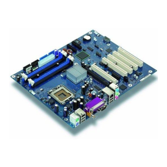
- Page 7 Übersicht/Overview Mainboard D1858 Diskettenlaufwerk / Floppy disk drive Interne Anschlüsse und Steckplätze / Stromversorgungsüberwachung / Internal connectors and slots Power supply control Bedienfeld / Front panel SCSI LED Stromversorgung / Power supply IDE-Laufwerke 1/2 / IDE-drives 1/2 Serial ATA3 Serial ATA4...
-
Page 9: Table Of Contents
Replacing the lithium battery....................26 BIOS update............................27 BIOS Recovery - Recovering System BIOS..................28 Microcode Update..........................29 Drivers .............................30 Annex .............................31 Mainboard Revision and BIOS Version....................31 Electrical Properties.........................32 APM and ACPI system status, energy-saving modes ..............33 Error messages ..........................34 Glossary ............................38 A26361-D1858-Z120-1-7419, Edition 2 English... -
Page 11: Mainboard D1858
Text in this typeface indicates screen outputs. Text in this bold typeface indicates the entries you make via the keyboard. Text in italics indicates commands or menu items. "Quotation marks" indicate names of chapters or terms. A26361-D1858-Z120-1-7419, Edition 2 English - 1... -
Page 12: Important Notes
Remove the power plug from the mains supply before inserting or removing boards containing ESDs. ● Always hold boards with ESDs by their edges. ● Never touch pins or conductors on boards fitted with ESDs. 2 - English A26361-D1858-Z120-1-7419, Edition 2... -
Page 13: List Of Features
(FAN3) Temperature monitoring CPU/ONB1/ONB2/OFFB ! / ! / ! / - SmartCard SystemLock (USB / serial) ! / - Fujitsu Siemens Computers Keyboard Power Button Support Special onboard features Silent Fan / Silent Fan LT ! / - System Guard / Silent Drives... - Page 14 FireWire™ * (6-Pin, IEEE 1394 port) USB Ports (2.0, ~480 Mbit/s) Serial Ports (RS232, FIFO, 16550 compatible) Parallel Port (EPP/ECP) for use with internal devices or optional Front or Rear panel not supported by standard power supplies 4 - English A26361-D1858-Z120-1-7419, Edition 2...
-
Page 15: Special Features
Silent Fan A micro controller developed by Fujitsu Siemens Computers monitors and controls the fans in the PC and thus prevents any unnecessary noise annoyance. Should the processor become in spite of full turning ventilator too hot, then the processor clock rate will automatically be reduced so that the system continues to run stably. - Page 16 USB Security is a BIOS function that offers protection against unauthorised access regardless of the operating system used. If USB Security is activated, the system can only be started, if the MemoryBird of Fujitsu Siemens Computers is connected to one of the existing USB-ports.
-
Page 17: Brief Instructions On Installing Mainboard
Equip the mainboard with the processor, heat sink and memory modules before installation if possible. Further information can be found in "Installing processor with heat sink" chapter. ► Open the casing as described in the operating manual. A26361-D1858-Z120-1-7419, Edition 2 English - 7... -
Page 18: Driver Installation
Driver installation ► Install the drivers for the chipset. You may find the driver on the "Drivers & Utilities" CD. Please refer to chapter "Drivers" for a description of installing drivers. 8 - English A26361-D1858-Z120-1-7419, Edition 2... -
Page 19: Interfaces And Connectors
LED 1 lights green - a connection exists (e.g. to a hub). LED is blinking green: activity LED 2 lights green or yellow: Link Mode: the LAN connection is active. 10 Mbit/s 100 Mbit/s green 1000 Mbit/s yellow A26361-D1858-Z120-1-7419, Edition 2 English - 9... -
Page 20: Internal Ports And Connectors
If you have connected audio devices to both Line out connections, only the connection on the front of the system is active. If you have connected audio devices to both Microphone connections, only the connection on the back of the system is active. 10 - English A26361-D1858-Z120-1-7419, Edition 2... -
Page 21: Pin Assignment Of Internal Ports
Indicates the system state APM or ACPI Recovery see "Jumper settings" chapter Password see "Jumper settings" chapter Speaker 0,5 W at 8 Ohm Serial ATA Signal Signal Transmit data positive Transmit data negative Receive data negative Receive data positive A26361-D1858-Z120-1-7419, Edition 2 English - 11... - Page 22 ATA66 Detect (low asserted) ADR 0 (high asserted) ADR 2 (high asserted) CS 1 (low asserted) CS 3 (low asserted) IDE-LED (low asserted) 1394 connector (internal header) Signal Signal TPA+ TPA- TPB+ TPB- +12 V +12 V 12 - English A26361-D1858-Z120-1-7419, Edition 2...
- Page 23 Chipcardreader on or not connected VCC 1 or 3 VCC 2 or 4 Data negative 1 or 3 Data negative 2 or 4 Data positive 1 or 3 Data positive 2 or 4 not connected A26361-D1858-Z120-1-7419, Edition 2 English - 13...
-
Page 24: Pci Express 16X / 1X
Motor A Enable (low asserted) Write Protect (low asserted) Drive B Select (low asserted) Read Data (low asserted) Drive A Select (low asserted) Side 1 Select (low asserted) Motor B Enable (low asserted) Disk Change (low asserted) 14 - English A26361-D1858-Z120-1-7419, Edition 2... - Page 25 LAN Link Icon Harddisk Action Icon SMB DATA BMC Alert Icon Message Icon Sleep Icon Power Icon Reserved for Future use LAN Active Icon P3V3P_DUAL Intrusion Signal Case open (low asserted) Intrusion switch present (low asserted) A26361-D1858-Z120-1-7419, Edition 2 English - 15...
-
Page 26: 16 - English
-5 V (P5VN) +5 V Auxiliary (VCC Aux) +5 V (VCC) +12 V (P12VP) +5 V (VCC) +12 V (P12VP) +5 V (VCC) Additional power supply ATX12 V Signal Signal +12 V +12 V 16 - English A26361-D1858-Z120-1-7419, Edition 2... -
Page 27: Serial Ata Interface (150 Mbyte/S)
Pin assignment of internal ports Power supply control (System monitoring) Signal Power Guard Control PS FAN Control PS FAN Sense A26361-D1858-Z120-1-7419, Edition 2 English - 17... -
Page 28: Jumper Settings
BIOS you need a Flash BIOS Diskette (see "BIOS update" chapter). Inserted The System BIOS executes from floppy drive A: and the inserted "Flash-BIOS- Diskette" restores the System BIOS on the mainboard. Not inserted Normal operation (default setting). 18 - English A26361-D1858-Z120-1-7419, Edition 2... -
Page 29: Add-On Modules / Upgrading
► Remove the heat sink. ► Press down the lever (1) and unhook it. ► Fold up the frame. ► Remove the old processor (2) from the socket. A26361-D1858-Z120-1-7419, Edition 2 English - 19... - Page 30 Insert the new processor in the socket so that the marking of the processor is aligned with the marking on the socket (a). ► Fold down the frame (1). ► Press the lever downward (2) until it is hooked in again (3). 20 - English A26361-D1858-Z120-1-7419, Edition 2...
-
Page 31: Mounting Heat Sink
► Secure the heat sink - depending on the model - with four screws or push it into the mounts. A26361-D1858-Z120-1-7419, Edition 2 English - 21... -
Page 32: Upgrading Main Memory
With a memory configuration of 4 Gbytes the visible and usable main memory can be reduced down to 3 Gbytes (depending on the system configuration). slot 4 Channel B slot 2 slot 3 Channel A slot 1 22 - English A26361-D1858-Z120-1-7419, Edition 4... - Page 33 At the same time flip the lateral holders upwards until the memory module snaps in place (2). Removing a memory module ► Push the clips on the right and left of the memory slot outward (1). ► Pull the memory module out of the memory slot (2). A26361-D1858-Z120-1-7419, Edition 2 English - 23...
-
Page 34: Adding Pci Express Cards
Monofunctional expansions cards: PCI/PCI Express expansion cards require a maximum of one interrupt, which is called the PCI interrupt INT A. Expansion cards that do not require an interrupt can be installed in any desired slot. 24 - English A26361-D1858-Z120-1-7419, Edition 2... - Page 35 PCI/PCI Express slot with IRQ sharing, check whether the expansion card properly supports IRQ sharing with the other devices on this PCI IRQ Line. The drivers of all cards and components on this PCI IRQ Line must also support IRQ sharing. A26361-D1858-Z120-1-7419, Edition 2 English - 25...
-
Page 36: Replacing The Lithium Battery
Press the locking lug in the direction of the arrow; the battery jumps somewhat out of the holder (1). ► Remove the battery (2). ► Push the new lithium battery of the identical type into the holder (3) and press it downward until it engages (4). 26 - English A26361-D1858-Z120-1-7419, Edition 2... -
Page 37: Bios Update
BIOS update BIOS update When should a BIOS update be carried out? Fujitsu Siemens Computers makes new BIOS versions available to ensure compatibility to new operating systems, new software or new hardware. In addition, new BIOS functions can also be integrated. -
Page 38: Bios Recovery - Recovering System Bios
Save the change and terminate BIOS Setup . The BIOS recovery has now been completed. The system restarts. Detailed information on the BIOS recovery is contained in the manual "BIOS Setup" ("Drivers & Utilities" CD). 28 - English A26361-D1858-Z120-1-7419, Edition 2... -
Page 39: Microcode Update
Intel refers to the use of the processor without microcode updates as operation outside the specifications. Safety for processor on Fujitsu Siemens Computers mainboards If the processor uses an old or incorrect microcode, error-free operation cannot be ensured. Fujitsu Siemens Computers has therefore implemented a function on its mainboards that interrupts the booting process if no suitable microcode is available for the installed processor. -
Page 40: Drivers
Insert the CD "Drivers & Utilities Collection" into the CD-ROM drive. ► If the CD does not start automatically, run the START.EXE programme in the main directory of the CD. ► Select DeskUpdate - Fully automatic installation . ► Follow the instructions on screen. 30 - English A26361-D1858-Z120-1-7419, Edition 2... -
Page 41: Annex
The BIOS version can be displayed in the BIOS Setup . ► Press F2 during booting to open the BIOS Setup . ► Press F1 . The BIOS version is specified on the displayed information page under the entry BIOS Release . A26361-D1858-Z120-1-7419, Edition 2 English - 31... -
Page 42: Electrical Properties
10 A BTX/ATX12V power supply -12 V ±10 % 0.05 A BTX/ATX12V power supply +5.0 V ±5 % BTX/ATX12V power supply +3.3 V ±5 % Standby voltage of power supply unit +5.0 V ±5 % 32 - English A26361-D1858-Z120-1-7419, Edition 2... -
Page 43: Apm And Acpi System Status, Energy-Saving Modes
One colour The power supply unit must provide sufficiently loadable 5 V standby voltage. To use the WOL functionality the power supply must provide a 5 V auxiliary voltage (5VSB) of at least 1 A. A26361-D1858-Z120-1-7419, Edition 2 English - 33... -
Page 44: Error Messages
Setup and exiting it again. Diskette drive A error Diskette drive B error Check the entry for the diskette drive in the Main menu of the BIOS Setup . Check the connections to the diskette drive. 34 - English A26361-D1858-Z120-1-7419, Edition 2... - Page 45 Keyboard controller error Connect another keyboard or another mouse. If the message is still displayed, please contact your sales outlet or customer service centre. Keyboard error Check that the keyboard is connected properly. A26361-D1858-Z120-1-7419, Edition 2 English - 35...
- Page 46 Switch the device off and on again. If the message is still displayed, please contact your sales outlet or customer service centre. System CMOS checksum bad - Default configuration used Call the BIOS Setup and correct the previously made entries or set the default entries. 36 - English A26361-D1858-Z120-1-7419, Edition 2...
- Page 47 Switch the device off and on again. If the message is still displayed, please contact your sales outlet or customer service centre. Verify CPU frequency selection in Setup The frequency setting for the processor is invalid. Correct the BIOS Setup and the setting. A26361-D1858-Z120-1-7419, Edition 2 English - 37...
-
Page 48: Glossary
System Management Bus Graphics Performance Accelerator SVGA Super Video Graphic Adapter Inter Integrated Circuit Video Graphic Adapter IAPC Instantly Available Power Wake On LAN Managed Desktop PC Design I/O Controller Hub Intelligent Drive Electronics 38 - English A26361-D1858-Z120-1-7419, Edition 2...
Need help?
Do you have a question about the D1858 and is the answer not in the manual?
Questions and answers