Table of Contents

Related Manuals for Fujitsu Siemens Computers D1171


Summary of Contents for Fujitsu Siemens Computers D1171
- Page 1 S Y S T E M B O A R D D 1 1 7 1 S Y S T E M B O A R D D 1 1 7 1 S Y S T E M B O A R D D 1 1 7 1 S Y S T E M B O A R D D 1 1 7 1 ADDITIONAL TECHNICAL ADDITIONAL TECHNICAL...
- Page 2 Is there ..any technical problem or other question you need clarified? Please contact: • Our Hotline: Mo-Fr: 8 a.m. - 6 p.m. Sat: 9 a.m. - 2 p.m. Tel.: ++49 (0) 180 3777 005 • your sales outlet The latest information on our products, tips, updates, etc., can be found on the Internet under: http://www.fujitsu-siemens.com...
- Page 4 Este manual ha sido impreso sobre papel reciclado. Questo manuale è stato stampato su carta da riciclaggio. Denna handbok är tryckt på recyclingpapper. Dit handboek werd op recycling-papier gedrukt. Herausgegeben von/Published by Fujitsu Siemens Computers GmbH A26361-D1171-Z180-4-7619 A26361-D1171-Z180-4-7619 A26361-D1171-Z180-4-7619 A26361-D1171-Z180-4-7619 Bestell-Nr./Order No.:...
- Page 5 System Board D1171 Additional Technical Manual January 2000 edition...
- Page 6 All other trademarks referenced are trademarks or registered trademarks of their respective owners, whose protected rights are acknowledged. Copyright ã Fujitsu Siemens Computers GmbH 2000 All rights, including rights of translation, reproduction by printing, copying or similar methods, even of parts are reserved.
-
Page 7: Table Of Contents
................10 USB power ........................10 Power ............................11 Power requirement ......................11 Power loadability......................11 Documentation ..........................11 Installing drivers ..........................11 Upgrading main memory ......................... 12 Troubleshooting..........................12 Message BIOS update......................12 The screen stays blank......................12 A26361-D1171-Z180-4-7619... -
Page 9: Introduction
You may find further information e. g. in the complete Technical Manual for the system board and in the description "BIOS Setup". Further information to drivers is provided on the supplied drivers diskettes or on the "Drivers & Utilities" or "ServerStart" CD. For detailed information please look at chapter "Installing drivers". A26361-D1171-Z180-4-7619 English -... -
Page 10: Features
Features Features The table shows two assembly versions of this system board as example. Function Version D1171-A Version D1171-B Processor socket PGA 370 PGA 370 Processor Intel Celeron or Pentium III Intel Celeron or Pentium µATX µATX Formfactor Front Side Bus in MHz... -
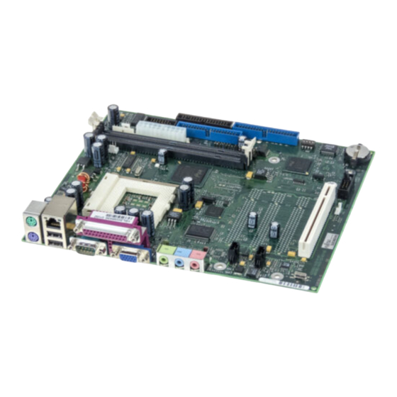
Page 11: Mechanics
4 = Parallel port 10 = Audio line-out 5 = VGA connector 11 = Audio line-in 6 = Game/Midi port 12 = Audio micro-in The components and connectors marked do not have to be present on the system board. English - 3 A26361-D1171-Z180-4-7619... - Page 12 7 = USB chipcard reader 15 = Power supply monitoring 8 = Fan 2 (e. g. for the processor) 16 = Intrusion detection The components and connectors marked do not have to be present on the system board. 4 - English A26361-D1171-Z180-4-7619...
-
Page 13: Connectors
Serial chipcard reader or internal serial port 2 (COM 2) external via optional cable Signal Signal DCD 2 DSR 2 SIN 2 RTS 2 SOUT 2 CTS 2 DTR 2 PC_On_Strobe VCC Auxiliary Not connected RESET (high asserted) English - 5 A26361-D1171-Z180-4-7619... -
Page 14: Front Panel Connector
1) Pin 8 is connected to VCC if audio is not onboard. Pin 8 is connected to GND if audio is onboard. 2) The sleep button (optional) functions only for operating systems with APM (not with ACPI). 6 - English A26361-D1171-Z180-4-7619... -
Page 15: Usb Chipcard Reader
Data positive down Not connected VCC auxiliary P3V3P Power OK (high asserted) Chipcard reader On (low pulse) Fan 2 connector Signal +12 V Fan sense Wake On LAN (WOL) connector Signal VCC Auxiliary Wake pulse (high asserted) English - 7 A26361-D1171-Z180-4-7619... -
Page 16: Cd-Rom Audio Connector (Internal)
CD-ROM audio connector (internal) Signal Left CD audio input CD GND CD GND Right CD audio input Auxiliary (MPEG, TV) audio connector (internal) Signal Left AUX audio input Analog GND Analog GND Right AUX audio input 8 - English A26361-D1171-Z180-4-7619... -
Page 17: Fan 1 Connector
PS FAN off request (low asserted) PS FAN full on (low asserted) PS FAN pulse SMB CLK SMB DATA VCC EEPROM Intrusion connector for case open detect for optional push-button (opener) Signal Case open (low asserted) Intrusion switch present (low asserted) English - 9 A26361-D1171-Z180-4-7619... -
Page 18: Configuration
If the power supply supports auxiliary voltage the USB interface is permanently powered except when the main supply is plugged off. Wakeup from ACPI S1-S4 state possible. Jumper 1-2 The USB interface is only powered in operating state. Wakeup from ACPI S1 state possible. 10 - English A26361-D1171-Z180-4-7619... -
Page 19: Power
If the CD doesn't start automatically call the START.EXE file in the main directory of the CD. Ê If the system board list is displayed select the system board or select under Driver the operating system used and the audio and video drivers. English - 11 A26361-D1171-Z180-4-7619... -
Page 20: Upgrading Main Memory
− Hardware and drivers of controllers (e. g. VGA, audio, LAN, SCSI controllers). The system board D1171 supports Save-to-RAM. Therefore the D1171 is certified by Intel and Microsoft. This support must be also guaranteed by the operating system, the extension boards and the power supply. For the time neither Windows 98 1st edition nor Windows NT4.0 support this function reliably.
Need help?
Do you have a question about the D1171 and is the answer not in the manual?
Questions and answers