Table of Contents
Advertisement
Quick Links
Advertisement
Table of Contents

Related Manuals for FIC AM35


Summary of Contents for FIC AM35
- Page 1 DOC No.: M01902 Rev. : A0 Date : 4, 2002 Part No. : 25-11635 -00...
-
Page 2: Handling Precautions
Notice Handling Precautions Warning: 1. Static electricity may cause damage to the integrated circuits on the motherboard. Before handling any motherboard outside of its protective packaging, ensure that there is no static electric charge in your body. 2. There is a danger of explosion if the battery is incorrectly replaced. - Page 3 Table of Contents Table of Contents Quick Reference (German) Quick Reference (French) Quick Reference (Spanish) Quick Reference (Japanese) Quick Reference (Chinese) Quick Reference (Simplified Chinese) |||||||||||||SC-1 Chapter 1 Overview Chapter 2 Installation Procedures...
- Page 4 AM35 Mainboard Manual Chapter 3 BIOS Setup...
- Page 5 Overview Chapter 1 Overview Ô Ô Ô 1 - 1...
- Page 6 AM35 Mainboard Manual Package Checklist The mainboard This user manual One FDD cable CD software One ATA100 cable IMPORTANT: AMD CPU HEAT SINK INSTALLATION Be ware finish heat sink install. Before you boot system, please check the heat sink is complete contact with die of CPU.
- Page 7 Overview The AM35 Mainboard 1 - 3...
-
Page 8: Main Features
AM35 Mainboard Manual Main Features 1 - 4... - Page 9 Overview 1 - 5...
-
Page 10: Fic Unique Innovation For Users (Novus)
AM35 Mainboard Manual FIC Unique Innovation for Users (NOVUS) - Enhanced Mainboard Features and System Support NOTE: 1. LogoGenie supports Award BIOS only. 2. If you create a Logo file (.bmp) by LogoGenie, the file size must ||||be 640 x 464 x 256 colors. - Page 11 Overview NOTE: However, if it is disabled and while boot the system, the POST screen will be held and shows you the message to let you know the current status of BIOS Guardian. To press G key will en- able the BIOS Guardian again; or simply to press the space bar will continue the booting process.
- Page 12 AM35 Mainboard Manual This Page Left Blank for Note 1 - 8...
-
Page 13: Installation Procedures
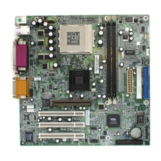
Installation Procedures Chapter 2 Installation Procedures WARNING: Excessive torque may damage the mainboard. When using an electric screwdriver on the mainboard, make sure that the torque is set to the allowable range of 5.0 ~ 8.0kg/cm. Mainboard components contain very delicate Integrated Circuit (IC) chips. - Page 14 AM35 Mainboard Manual Quick Reference (from Page 2-2 to 2-4) Mainboard Layout 2 - 2...
- Page 15 Installation Procedures Clear CMOS, Clear Password, FSB Speed Select Front Panel Block Cable Connection 2 - 3...
-
Page 16: Set System Jumpers
AM35 Mainboard Manual CPU Fan Installation CAUTION: 1. The heatsink and fan you installed must be approved by AMD. 2. The mainboard must be placed on a solid place to avoid shaking |||||while install the heatsink and fan on the board. - Page 17 Installation Procedures 2 - 5...
-
Page 18: Install Memory Modules
AM35 Mainboard Manual 2). Install Memory Modules 2 - 6... -
Page 19: Install The Cpu
Installation Procedures 3). Install the CPU CAUTION: 1. The heat sink and fan you installed must be approved by AMD. 2. The mainboard must be placed on a solid place to avoid shaking |||||while install the heat sink and fan on the board. 3. -
Page 20: Install Expansion Cards
AM35 Mainboard Manual 4). Install Expansion Cards 2 - 8... - Page 21 Installation Procedures CAUTION: Make sure to unplug the power supply when adding or removing expansion cards or other system components. Failure to do so may cause severe damage to both the mainboard and expansioncards. Always observe static electricity precautions. Please read Handling Precautions at the start of this manual. 2 - 9...
-
Page 22: Connect Devices
AM35 Mainboard Manual 5). Connect Devices 2 - 10... - Page 23 Installation Procedures 2 - 11...
- Page 24 AM35 Mainboard Manual 2 - 12...
- Page 25 Installation Procedures 2 - 13...
- Page 26 AM35 Mainboard Manual NOTE: When a dual power LED is used, Pin 2 is for green one and Pin 4 is for yellow one. If single power LED installed, Pin 2 is for positive and Pin 4 is for negative.
- Page 27 Installation Procedures 2 - 15...
- Page 28 AM35 Mainboard Manual 2 - 16...
- Page 29 Installation Procedures 2 - 17...
- Page 30 AM35 Mainboard Manual 2 - 18...
-
Page 31: Cmos Setup Utility
BIOS Setup Chapter 3 BIOS Setup CMOS Setup Utility 3 - 1... - Page 32 AM35 Mainboard Manual Standard CMOS Setup Date Time 3 - 2...
- Page 33 BIOS Setup Hard Disks Hard Disk Configurations Drive A / Drive B Floppy 3 Mode Support Video Halt On 3 - 3...
-
Page 34: Advanced Bios Features
AM35 Mainboard Manual Advanced BIOS Features Virus Warning CPU Internal Cache External Cache CPU L2 Cache ECC Checking Processor Number Feature 3 - 4... - Page 35 BIOS Setup Hard Disk Boot Priority First/Second/Third Boot Device Boot Other Device Swap Floppy Drive Boot Up Floppy Seek Boot Up Numlock Status Gate A20 Option Typematic Rate Setting 3 - 5...
- Page 36 AM35 Mainboard Manual Typematic Rate (Chars/Sec) Typematic Delay (Msec) Security Option APIC Mode MPS Version Control For OS OS Select For DRAM > 64MB HDD S.M.A.R.T. Capability Report No FDD For WIN 95 3 - 6...
-
Page 37: Advanced Chipset Features
BIOS Setup Video BIOS Shadow Full Screen LOGO Show BIOS Guardian NOTE: Please disable this BIOS feature about BIOS Guardian before you start to reflash BIOS. Advanced Chipset Features DRAM Clock/Drive Control Current FSB Frequency, Current DRAM Frequency 3 - 7... - Page 38 AM35 Mainboard Manual DRAM Clock DRAM Timing DRAM CAS Latency Bank Interleave Precharge to Active (Trp) Active to Precharge (Tras) Active to CMD (Trcd) DRAM Queue Depth DRAM Command Rate 3 - 8...
- Page 39 BIOS Setup AGP & P2P Bridge Control AGP Aperture Size AGP Mode AGP Driving Control / AGP Driving Value AGP Fast Write AGP Master 1 WS Write AGP Master 1 WS Read CPU & PCI Bus Control PCI1/2 Master 0 WS Write PCI1/2 Post Write 3 - 9...
- Page 40 AM35 Mainboard Manual PCI Delay Transaction Memory Hole System BIOS Cacheable Video RAM Cacheable VGA Share Memory Size 3 - 10...
-
Page 41: Integrated Peripherals
BIOS Setup Integrated Peripherals VIA OnChip IDE Device OnChip IDE Channel0 OnChip IDE Channel1 IDE Prefetch Mode 3 - 11... - Page 42 AM35 Mainboard Manual Primary Master PIO Primary Slave PIO Secondary Master PIO Secondary Slave PIO Primary Master UDMA Primary Slave UDMA Secondary Master UDMA Secondary Slave UDMA 3 - 12...
- Page 43 BIOS Setup VIA OnChip PCI Device VIA-3058 AC97 Audio VIA-3068 MC97 Modem SuperIO PCI Device Onboard FDC Controller Onboard Serial Port 1 Onboard Serial Port 2 UART Mode Select UR2 Duplex Mode 3 - 13...
- Page 44 AM35 Mainboard Manual Onboard Parallel Port Parallel Port Mode ECP Mode Use DMA Game Port Address Midi Port Address Midi Port IRQ Init Display First OnChip USB Controller USB Keyboard Support 3 - 14...
- Page 45 BIOS Setup USB Mouse Support IDE HDD Block Mode Onboard Lan Device Onboard Lan Boot ROM 3 - 15...
-
Page 46: Power Management Setup
AM35 Mainboard Manual Power Management Setup ACPI function ACPI Suspend Type Power Management HDD Power Down 3 - 16... - Page 47 BIOS Setup Suspend Mode Video Off Option Video Off Method MODEM Use IRQ Soft-Off by PWR-BTTN State After Power Failure 3 - 17...
- Page 48 AM35 Mainboard Manual IRQ/Event Activity Detect USB Resume From S3 LPT & COM HDD & FDD PCI Master PowerOn by PCI Card Modem Ring Resume RTC Alarm Resume 3 - 18...
- Page 49 BIOS Setup Date (of Month) Resume Time (hh:mm:ss) Primary INTR IRQs Activity Monitoring 3 - 19...
-
Page 50: Pnp/Pci Configurations
AM35 Mainboard Manual PnP/PCI Configurations PNP OS Installed Reset Configuration Data Resources Controlled By PCI/VGA Palette Snoop 3 - 20... -
Page 51: Pc Health Status
BIOS Setup Assign IRQ For VGA Assign IRQ For USB INT Pin 1/2/3/4 Assignment PC Health Status Shutdown Temperature 3 - 21... -
Page 52: Frequency/Voltage Control
AM35 Mainboard Manual Voltage VCORE / Voltage + 2.5 V / Voltage +3.3 V / Voltage +5 V / Voltage +12 V / Voltage 5VSB / Voltage Battery / SYSTEM Temp. / CPU Temp. / CPU FAN Speed / Chassis FAN Speed... - Page 53 BIOS Setup CPU Host/PCI Clock/3V66 Load Fail-Safe Defaults Load Optimized Defaults Supervisor/User Password 3 - 23...
- Page 54 AM35 Mainboard Manual Save and Exit Setup Exit without Saving 3 - 24...
Need help?
Do you have a question about the AM35 and is the answer not in the manual?
Questions and answers