
Related Manuals for FIC AM39L


Summary of Contents for FIC AM39L
- Page 1 AM39L MAINBOARD MANUAL DOC No.: M03401 Rev. : A1 Date : 6, 2003 Part No. : 25-11673-01...
- Page 2 Notice Handling Precautions Warning: 1. Static electricity may cause damage to the integrated circuits on the motherboard. Before handling any motherboard outside of its protective packaging, ensure that there is no static electric ||||||charge in your body. 2. There is a danger of explosion if the battery is incorrectly replaced.
-
Page 3: Table Of Contents
Package Checklist ................. 1-2 The AM39L Mainboard ............1-3 Main Features ................1-4 FIC Unique Innovation for Users (NOVUS) - Enhanced Mainboard Features and System Support ..... 1-6 Chapter 2 Installation Procedures Quick Reference (from Page 2-2 to 2-4) .......... 2-2 Mainboard Layout .............. - Page 4 AM39L Mainboard Manual SPDIF Out Connector ............2-14 IEEE 1394 Connectors (mfg. optional) ....... 2-15 PS/2 Keyboard and Mouse Connector ......2-15 RJ45 LAN Connector ............2-16 Serial Port Connector ............2-16 Audio I/O Jacks ..............2-17 Front Audio Connector ............. 2-17 Printer Connector .............
-
Page 5: Chapter 1 Overview
Overview Chapter 1 Overview The new board is an MicroATX sized motherboard supporting the latest gen- eration of AMD processors at industry leading speeds. By utilizing DDR ( ® Double Data Rate ) transfer rate the 100/133/166 MHz system bus effectively reaches Front Side Bus speeds of 200/266/333 MHz. -
Page 6: Package Checklist
AM39L Mainboard Manual Package Checklist If you discover any item below was damaged or lost, please contact your vendor. þ þ The mainboard This user manual þ þ One FDD cable CD software þ þ One ATA100 cable I/O shielding IMPORTANT: AMD CPU HEAT SINK INSTALLATION Be ware finish heat sink install. -
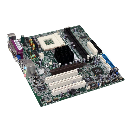
Page 7: The Am39L Mainboard
Overview The AM39L Mainboard 1 - 3... -
Page 8: Main Features
AM39L Mainboard Manual Main Features Easy Installation ||BIOS with support for Plug and Play, auto detection of IDE hard drives, ||LS-120|drives, IDE ZIP drives, Windows 98SE, Windows ME, Windows ||NT, Windows 2000, Windows XP, and OS/2. Leading Edge Chipset VIA KM400 is a single-chip North Bridge for AMD CPUs with 200/266/333 MHz Front Side Bus with AGP and PCI plus advanced memory controller that supports DDR 200/266/333 SDRAM. - Page 9 Overview AGP and PCI Expansion Slots One AGP Bus and three PCI Bus expansion slots provided the room to install a full range of add-on cards. Compact Onboard Audio Subsystem Embeded in VIA VT8235CE, an integrated high bandwidth V-Link client controller, direct sound AC97 audio subsystem.
-
Page 10: Fic Unique Innovation For Users (Novus) - Enhanced Mainboard Features And System Support
AM39L Mainboard Manual FIC Unique Innovation for Users (NOVUS) - Enhanced Mainboard Features and System Support LogoGenie A user friendly GUI supporting Windows 95/98/98SE (not Windows 2000/ NT/ME/XP), LogoGenie allows you to customize, create or select a Logo which will be displayed when the system is booting. -
Page 11: Chapter 2 Installation Procedures
Installation Procedures Chapter 2 Installation Procedures The mainboard has several user-adjustable jumpers on the board that allow you to configure your system to suit your requirements. This chapter contains information on the various jumper settings on your mainboard. To set up your computer, you must complete the following steps: Step 1 - Set system jumpers Step 2 -... -
Page 12: Quick Reference (From Page 2-2 To 2-4)
AM39L Mainboard Manual Quick Reference (from Page 2-2 to 2-4) Mainboard Layout * When link to Line_Out jack, please use a speaker that with amplifier. 2 - 2... -
Page 13: Clear Password
Installation Procedures Clear CMOS, FSB Speed Select, BIOS Flash Protect , Clear Password Front Panel Block Cable Connection 2 - 3... -
Page 14: Cpu Fan Installation
AM39L Mainboard Manual CPU Fan Installation CAUTION: The heatsink and fan you installed must be approved by AMD. 2. The mainboard must be placed on a solid place to avoid shaking |||||while install the heatsink and fan on the board. -
Page 15: Set System Jumpers
Installation Procedures 1). Set System Jumpers Clear CMOS (1) Turn off your computer (2) Place the jumper cap onto the pinpair 2-3 at least 6 seconds to clear CMOS (3) Place the jumper cap onto the pinpair 1-2 to Normal (4) Turn on your computer until CMOS checksum error appears (5) Hold down the Delete key when boots (6) Enter the BIOS Setup to re-enter user preferences, save it and exit. -
Page 16: Front Side Bus Frequency
AM39L Mainboard Manual Front Side Bus Frequency The jumpers together decide the setting of FSB frequency of the mainboard. Clear Password (1). Turn off your computer (2). Short this jumper by placing a jumper cap on it (3). Turn on your computer (4). -
Page 17: Install Memory Modules
Installation Procedures 2). Install Memory Modules Locate the DIMM slots on the mainboard. Install the DIMM straight down into the DIMM slot using both hands. The clip on both ends of the DIMM slot will close up to hold the DIMM in place when the DIMM reaches the slot bottom. -
Page 18: Install Expansion Cards
AM39L Mainboard Manual To install the CPU, do the following: Lift the lever on the side of the CPU socket. Handle the chip by its edges and try not to touch any of the pins. Place the CPU in the socket. Do not force the chip. The CPU should slide easily into the socket. - Page 19 Installation Procedures CAUTION: Make sure to unplug the power supply when adding or removing expansion cards or other system components. Failure to do so may cause severe damage to both the mainboard and expansioncards. Always observe static electricity precautions. Please read Handling Precautions at the start of this manual. To install an expansion card, follow the steps below: Remove the computer chassis cover and select an empty expansion slot.
-
Page 20: Connect Devices
AM39L Mainboard Manual 5). Connect Devices Floppy Diskette Drive Connector This connector provides the connection with your floppy disk drive. The red stripe of the ribbon cable must be the same side with the Pin 1. IDE Device Connectors These two connectors are used for your IDE hard disk drives, CD drives, LS- 120|drives, or IDE ZIP drives. -
Page 21: Power Connectors
Installation Procedures Power Connectors The 20-pin male block connector is connected to the ATX power supply. The 4-pin male block connector is for the 12V power use. The connectors are linked with your ATX power supply. The plug from the power supply will only insert in one orientation because of the different hole sizes. -
Page 22: Front Panel Block Connector
AM39L Mainboard Manual Front Panel Block Connector This block connector includes the connectors for linking with Power LED (3-pin), HDD LED, power button, power/sleep button, reset buttonon the front panel of the sys- tem case. Please identify polarities of plug wires for the case speaker and LEDs. -
Page 23: Fan Connectors
Installation Procedures (4) Power Button is connected with power button. Push this switch allows the system to be turned on and off rather than using the power supply button. IR is a pinheader that is used for linking with your ID device to allow transmis- sion of data to another system that also supports the IR feature. -
Page 24: Spdif Out Connector
AM39L Mainboard Manual CAUTION: Improper orientation of SPDIF connection may cause damage of your device. SPDIF Out Connector The mainboard equipped one 1x3 pinheader. It is used for SPDIF digi- tal audio output. Pin 1 is VCC, Pin 2 is SPDIF, Pin3 is GND. -
Page 25: Ieee 1394 Connectors (Mfg. Optional)
Installation Procedures IEEE 1394 Connectors (mfg. optional) The 2 optional 1394 pinheaders on the board provides you with two connec- tions with the peripherals which own 1394 connectors. The pin definitions of the 1394 pinheaders are listed below also. PS/2 Keyboard and Mouse Connector These two 6-pin female (PS/2 keyboard is purple color and PS/2 mouse is green color) connectors are used for your PS/2 keyboard and PS/2 mouse. -
Page 26: Rj45 Lan Connector
AM39L Mainboard Manual RJ45 LAN Connector The RJ45 jack of LAN port is used for the LAN cable plug. Serial Port Connector COM1 (9-pin D-sub male connector with teal color) allows you to connect with your devices that use serial ports, such as a serial mouse or an external modem. -
Page 27: Audio I/O Jacks
Installation Procedures Audio I/O Jacks LINE_OUT (lime) can be connected to headphones or preferably powered speakers. LINE_IN (light blue) allows tape players or other audio sources to be recorded by your computer or played through the LINE_OUT. MIC_IN (pink) allows microphones to be connected for audio input. Front Audio Connector The mainboard has a front panel audio connector... -
Page 28: Printer Connector
AM39L Mainboard Manual Printer Connector This 25-pin D-Sub female burgundy-colored connector is attached to your printer. CRT Connector The connector is linked with your monitor. The pinheaders pin assignments are shown at right side. 2 - 18... -
Page 29: Universal Serial Bus Connectors
Installation Procedures Universal Serial Bus Connectors The mainbaord have six USB ports; four USB black jacks that integrated on the edge of the board, the other two USB ports (pinheaders) on the board. They allows users to attach with USB devices either from rear or front panels. Please note that your operating system must support USB 1.1/2.0 features. - Page 30 AM39L Mainboard Manual This Page Left Blank for Note 2 - 20...
-
Page 31: Chapter 3 Bios Setup
BIOS Setup Chapter 3 BIOS Setup The mainboard comes with the chip that Award BIOS that contains the ROM Setup information of your system. (This chip serves as an interface between the processor and the rest of the mainboard components.) This section ex- plains the information contained in the Setup program and tells you how to modify the settings according to your system configuration. -
Page 32: Standard Cmos Setup
AM39L Mainboard Manual Standard CMOS Setup The Standard CMOS Setup screen is displayed above. Each item may have one or more option settings. The system BIOS automatically detects memory size, thus no changes are necessary. Use the arrow keys to highlight the item and then use PgUp or PgDn keys to select the value you want in each item. - Page 33 BIOS Setup Hard Disks This field records the specifications for all non-SCSI hard drives installed in the system. The onboard PCI IDE connectors provide Primary and Sec- ondary channels for connecting up to four IDE hard disks or other IDE devices.
-
Page 34: Advanced Bios Features
AM39L Mainboard Manual Advanced BIOS Features Virus Warning This feature will prompt uses a warning message, when any write boot sector commend executed. The options are: Enabled, Disabled. CPU Internal Cache When enabled, improves the system performance. Disable this item when testing or trouble-shooting. - Page 35 BIOS Setup Hard Disk Boot Priority This feature will auto detect all hard disks of bootable device on the system. It also allows users to select hard disk device booting priority. First/Second/Third Boot Device This feature allows user to select the boot device priority. The options are: Floppy, LS120, Hard Disk, ZIP100, USB-FDD, USB-ZIP, USB-CDROM, USB- HDD, LAN, Disabled.
- Page 36 AM39L Mainboard Manual Typematic Delay (Msec) This feature is available only if the item, Typematic Rate Setting, is set at Enabled. Sets the delay time before a character is repeated. The options are: 250, 500, 750, 1000 millisecond. Security Option Allows to set the security level of the system.The options: Setup, System.
-
Page 37: Advanced Chipset Features
BIOS Setup BIOS Guardian and Reflash BIOS BIOS Guardian by default is enabled, thus effectively acts as a fire- wall against viruses that can attack the BIOS while the system is running. It must be disabled before reflash BIOS. The steps below show you how to off and on BIOS Guardian when reflash BIOS: 1. - Page 38 AM39L Mainboard Manual DRAM Clock/Drive Control Current FSB Frequency, Current DRAM Frequency This item allows you to get current FSB and DRAM frequencies. DRAM Clock The feature allows users to decide DRAM clock. The options are: By SPD, 133 MHz, 166 MHz.
- Page 39 BIOS Setup Active to CMD (Trcd) This item sets the timing parameters for the system memory such as the CAS (Column Address Strobe) and RAS (Row Address Strobe). The options are: 3T, 2T. DRAM Burst Length This item sets the timing parameters for the DRAM burst length. The options are: 4, 8.
- Page 40 AM39L Mainboard Manual OnChip IDE Channel0/1 When enabled, allows you to use the onboard primary/secondary PCI IDE. If a hard disk controller card is used, set at Disabled. The options are: Enabled, Disabled. IDE Prefetch Mode When set at Enabled, it allows data to be posted to and prefetched from the primary IDE data ports.
- Page 41 BIOS Setup IDE HDD Block Mode Block mode is also called block transfer, multiple commands, or multiple sector read/write. If your IDE hard drive supports block mode (most new drives do), select Enabled for automatic detection of the optimal number of block read/writes per sector the drive can support.
- Page 42 AM39L Mainboard Manual AGP Fast Write This feature allows you to set AGP fast write mode. The options are: Disabled, Enabled. AGP 3.0 Calibration cycle This feature allows users to enable or disable AGP 3.0cablibration cycle. The options are: Disabled, Enabled.
-
Page 43: Integrated Peripherals
BIOS Setup Memory Hole When you install a Legacy ISA card, this feature allows you to select the memory hole address range of the ISA cycle when the processor accesses the selected address area. Please read your card manual for detail informa- tion. - Page 44 AM39L Mainboard Manual OnChip IDE Channel0/1 When enabled, allows you to use the onboard primary/secondary PCI IDE. If a hard disk controller card is used, set at Disabled. The options are: Enabled, Disabled. IDE Prefetch Mode When set at Enabled, it allows data to be posted to and prefetched from the primary IDE data ports.
- Page 45 BIOS Setup IDE HDD Block Mode Block mode is also called block transfer, multiple commands, or multiple sector read/write. If your IDE hard drive supports block mode (most new drives do), select Enabled for automatic detection of the optimal number of block read/writes per sector the drive can support.
- Page 46 AM39L Mainboard Manual SuperIO Device Onboard FDC Controller When enabled, the floppy diskette drive (FDD) controller is activated. The options are: Enabled, Disabled. Onboard Serial Port 1 If the serial port 1 uses the onboard I/O controller, you can modify your serial port parameters.
-
Page 47: Power Management Setup
BIOS Setup Power Management Setup ACPI function This item allows you to disable the ACPI function. The options are: Enabled, Disabled. ACPI Suspend Type This item allows you to select ACPI suspend types. The options are: S1(POS), S3 (STR), S1&S3. Power Management Option This item allows you to adjust the power management features. - Page 48 AM39L Mainboard Manual Suspend Mode When disabled, the system will not enter Suspend mode. The specified time option defines the idle time the system takes before it enters Suspend mode. The options are: Disable, 1, 2, 4, 6, 8, 10, 20, 30, 40 Min, 1 Hour.
- Page 49 BIOS Setup IRQ/Event Activity Detect PS2KB Wakeup Select This item allows you to select Hot Key or Password to wake-up the system by PS2 Keyboard. When select Password, please press ENTER key to change password max 8 numbers. The options are : Hot key, Password. PS2KB Wakeup from S1-S5 It allows you to set a Hot Key to wake-up the system by PS2 Keyboard.
- Page 50 AM39L Mainboard Manual PowerOn by PCI Card When set at Enabled, any PCI-PM event awakes the system from a PCI-PM controlled state. The options are Disabled, Enabled. Wake Up On LAN/Ring When set at Enabled, an input signal comes from the other client/server on the LAN/ring awakes the system from a soft off state if connected over LAN/modem.
-
Page 51: Pnp/Pci Configurations
BIOS Setup PnP/PCI Configurations PNP OS Installed If your operating system is a Plug-and-Play one, such as Windows NT, Windows 95, select Yes. The options are: No, Yes. Reset Configuration Data Enabling it to reset the system Extended System Configuration Data (ESCD) when you exit Setup if you have installed a new add-on card and the system reconfiguration has caused such a serious conflict that the operat- ing system can not boot. -
Page 52: Pc Health Status
AM39L Mainboard Manual Assign IRQ For VGA If your PCI VGA card devices do not need an IRQ, select Disabled; there- fore, an IRQ can be released for the system use. The options are: Enabled, Disabled. Assign IRQ For USB If your USB devices do not need an IRQ, select Disabled;... -
Page 53: Supervisor/User Password
BIOS Setup Supervisor/User Password To enable the Supervisor/User passwords, select the item from the Standard CMOS Setup. You will be prompted to create your own password. Type your password up to eight characters and press Enter. You will be asked to confirm the password. - Page 54 AM39L Mainboard Manual This Page Left Blank for Note 3 - 24...
Need help?
Do you have a question about the AM39L and is the answer not in the manual?
Questions and answers